EP2130083B1 - Optisches okularsystem - Google Patents
Optisches okularsystem Download PDFInfo
- Publication number
- EP2130083B1 EP2130083B1 EP08734859A EP08734859A EP2130083B1 EP 2130083 B1 EP2130083 B1 EP 2130083B1 EP 08734859 A EP08734859 A EP 08734859A EP 08734859 A EP08734859 A EP 08734859A EP 2130083 B1 EP2130083 B1 EP 2130083B1
- Authority
- EP
- European Patent Office
- Prior art keywords
- lens
- ocular system
- image
- optic
- deflection element
- Prior art date
- Legal status (The legal status is an assumption and is not a legal conclusion. Google has not performed a legal analysis and makes no representation as to the accuracy of the status listed.)
- Not-in-force
Links
- 230000003287 optical effect Effects 0.000 title claims abstract description 41
- 238000003384 imaging method Methods 0.000 claims abstract description 35
- 238000006073 displacement reaction Methods 0.000 claims abstract description 12
- 210000001747 pupil Anatomy 0.000 claims description 6
- 210000003128 head Anatomy 0.000 claims description 3
- 210000000887 face Anatomy 0.000 claims 2
- 230000002950 deficient Effects 0.000 claims 1
- 208000014733 refractive error Diseases 0.000 abstract description 9
- 208000029091 Refraction disease Diseases 0.000 abstract description 4
- 230000004430 ametropia Effects 0.000 abstract description 4
- 239000000463 material Substances 0.000 description 19
- 102220616555 S-phase kinase-associated protein 2_E48R_mutation Human genes 0.000 description 9
- WKBPZYKAUNRMKP-UHFFFAOYSA-N 1-[2-(2,4-dichlorophenyl)pentyl]1,2,4-triazole Chemical compound C=1C=C(Cl)C=C(Cl)C=1C(CCC)CN1C=NC=N1 WKBPZYKAUNRMKP-UHFFFAOYSA-N 0.000 description 6
- 239000011031 topaz Substances 0.000 description 6
- 229910052853 topaz Inorganic materials 0.000 description 6
- 239000011521 glass Substances 0.000 description 5
- 230000004075 alteration Effects 0.000 description 2
- 238000011161 development Methods 0.000 description 2
- 230000018109 developmental process Effects 0.000 description 2
- 239000006185 dispersion Substances 0.000 description 2
- 239000011159 matrix material Substances 0.000 description 2
- 229920003229 poly(methyl methacrylate) Polymers 0.000 description 2
- 239000004417 polycarbonate Substances 0.000 description 2
- 239000004926 polymethyl methacrylate Substances 0.000 description 2
- 101100129500 Caenorhabditis elegans max-2 gene Proteins 0.000 description 1
- 241000700608 Sagitta Species 0.000 description 1
- 241000897276 Termes Species 0.000 description 1
- 230000006978 adaptation Effects 0.000 description 1
- 230000015572 biosynthetic process Effects 0.000 description 1
- 238000011109 contamination Methods 0.000 description 1
- 230000000694 effects Effects 0.000 description 1
- 230000002349 favourable effect Effects 0.000 description 1
- 238000013507 mapping Methods 0.000 description 1
- 239000004033 plastic Substances 0.000 description 1
- 229920003023 plastic Polymers 0.000 description 1
- 229920000515 polycarbonate Polymers 0.000 description 1
- 229920002223 polystyrene Polymers 0.000 description 1
- 230000007704 transition Effects 0.000 description 1
Images


Classifications
-
- G—PHYSICS
- G02—OPTICS
- G02B—OPTICAL ELEMENTS, SYSTEMS OR APPARATUS
- G02B27/00—Optical systems or apparatus not provided for by any of the groups G02B1/00 - G02B26/00, G02B30/00
- G02B27/01—Head-up displays
- G02B27/017—Head mounted
- G02B27/0172—Head mounted characterised by optical features
-
- G—PHYSICS
- G02—OPTICS
- G02B—OPTICAL ELEMENTS, SYSTEMS OR APPARATUS
- G02B25/00—Eyepieces; Magnifying glasses
- G02B25/001—Eyepieces
-
- G—PHYSICS
- G02—OPTICS
- G02B—OPTICAL ELEMENTS, SYSTEMS OR APPARATUS
- G02B17/00—Systems with reflecting surfaces, with or without refracting elements
- G02B17/08—Catadioptric systems
- G02B17/0856—Catadioptric systems comprising a refractive element with a reflective surface, the reflection taking place inside the element, e.g. Mangin mirrors
-
- G—PHYSICS
- G02—OPTICS
- G02B—OPTICAL ELEMENTS, SYSTEMS OR APPARATUS
- G02B27/00—Optical systems or apparatus not provided for by any of the groups G02B1/00 - G02B26/00, G02B30/00
- G02B27/01—Head-up displays
- G02B27/0101—Head-up displays characterised by optical features
- G02B2027/011—Head-up displays characterised by optical features comprising device for correcting geometrical aberrations, distortion
-
- G—PHYSICS
- G02—OPTICS
- G02B—OPTICAL ELEMENTS, SYSTEMS OR APPARATUS
- G02B27/00—Optical systems or apparatus not provided for by any of the groups G02B1/00 - G02B26/00, G02B30/00
- G02B27/01—Head-up displays
- G02B27/017—Head mounted
- G02B2027/0178—Eyeglass type
Definitions
- the present invention relates to an eyepiece optical system having imaging optics which images an image formed in an object plane so as to be perceived by a user in an image plane, the imaging optics comprising a first negative refractive power lens and a first refractive power redirecting element which effects a convolution of the beam path by means of a single reflection.
- Such an optical eyepiece system is for example in the EP 1 513 000 A1 described.
- the eyepiece system is used in an HMD (Head Mounted Display) device.
- HMD Head Mounted Display
- the aforementioned eyepiece system can also be used in microscopes or telescopes.
- the disadvantage is that, for example, when used in an HMD device, the user, if he must wear glasses due to a spherical refractive error, wearing these glasses even when using the HMD device.
- wearing the glasses and additionally wearing the HMD device is often considered uncomfortable.
- the object of the invention is achieved in an optical eyepiece system of the type mentioned above in that the first lens and the object plane form a first optical group and a displacement unit is provided which, for the correction of a spherical ametropia of the user, the distance between the first optical group and the deflecting element can change.
- This allows a user with spherical refractive error, the optical eyepiece without use his glasses, since the adaptation to the spherical refractive error can be realized by means of the displacement unit.
- the displacement unit is that to a distance within the imaging optics is changed, so that the user does not have to move relative to the optical eyepiece to be able to perceive the image sharply.
- the displacement unit may be configured so that it can move the first optical group along the optical axis of the imaging optics. In particular, it can provide a displacement of ⁇ 2 mm. This can cover a dioptric range of ⁇ 3.5. The displacement along the optical axis minimizes displacement-related aberrations.
- the distance between the first lens and the object plane is preferably fixed or constant. So it's the optics group as a whole postponed.
- Both the boundary surface of the first lens facing the deflection element and the boundary surface of the deflection element facing the first lens can each be convexly curved. This is a spatially very favorable variant, since then there are no difficulties with respect to the sockets of the first lens and deflection element, since the smallest distance between the apexes on the optical axis occurs between the two boundary surfaces. Thus, there is enough space for the versions.
- the deflecting element is in particular formed in one piece. Thus, no complicated adjustment is necessary.
- the entry and exit surface of the deflection element has a different curvature.
- the surface on which the reflection takes place is preferably formed as a plane surface (ie with an infinitely large curvature).
- the deflecting element can also be designed in several pieces.
- it may be, for example, a 90 ° prism with a planar deflection surface and a plane entry and a flat exit side.
- a plano-convex lens is applied with its flat side.
- the plano-convex lenses for example, can be cemented, glued or sprinkled with the prism. Any other type of connection is possible.
- the two boundary surfaces of the first lens as well as the entrance and exit surfaces of the deflection element are preferably aspherically curved, wherein the aspherical surfaces are centered rotationally symmetrically and to the optical axis of the imaging optics.
- the boundary surface of the deflecting element facing the first lens is designed as a diffractive surface. This color aberration can be corrected excellent.
- the deflection element can cause the folding of the beam path by 70 ° - 110 °. A deflection of 90 ° is preferred.
- the eyepiece system may include a picture element for generating the image in the object plane.
- the picture element itself can be arranged in the object plane.
- a self-luminous or a non-self-illuminating display element can be provided as the picture element, in particular the display element can have a multiplicity of pixels that can be controlled independently of one another, which can be arranged in particular in rows and columns.
- the picture element may be an LCD module, an LCoS module or a tilting mirror matrix.
- the first lens and the picture element may be held in a single frame. This makes it easy to keep the distance between picture element and lens constant.
- the first lens and the picture element can be positively connected with each other. This is possible, for example, by means of a corresponding version.
- the imaging optics and the picture element form an eye module.
- Such an eye module can be provided twice, so that there is an eye module for each eye of the user.
- This binokulare embodiments can be realized.
- the distance between the optical group and the deflecting element in both eye modules can be changed independently of one another. This makes it possible to compensate for different spherical refractive errors of the two eyes of the user.
- the beam path in the eye module from the image plane to the exit pupil of the imaging optics may be substantially L-shaped, wherein the eye modules are arranged so that the distance between the two optical groups is smaller than the distance between the two deflecting elements.
- the eye modules arranged so are that the distance of the two optical groups is greater than the distance between the two deflection elements.
- a shading aperture may be provided between the picture element and the first lens.
- This diaphragm is preferably used to suppress unwanted scattered light.
- the shading diaphragm can in particular have a contour adapted to the contour of an imaging region of the image element. So she can e.g. have a rectangular transmissive region when the image-forming region is also rectangular. In particular, the transmissive area in the aperture is slightly larger than the imaging area of the picture element.
- a display device with an optical eyepiece system which further comprises a head-on holding module, wherein the imaging optics is attached to the holding module and the imaged by the imaging optics image of a user carrying the display device is perceptible.
- the picture element can furthermore be fastened to the holding module.
- the holding module can be designed as a spectacle-like frame, cap, cap, band or in any other way.
- the eyepiece system according to the invention (including its developments) can also be used in a microscope and a telescope, so that a corresponding microscope or telescope is present.
- Fig. 1 shows an embodiment of the optical eyepiece system 1, 2 according to the invention, in which it is used in a to be worn on the head of a user binocular display device 3.
- the display device 3 which may also be referred to as a HMD (head mounted display device), comprises a holding module 4, which is shown schematically in FIG Fig. 1 is shown and the two optical eyepiece 1, 2 receiving housing 5 and two lateral bracket 6 and 7 comprises.
- the holding module 4 is thus designed in the manner of a spectacle frame, which the user can put on in the same way as a pair of spectacles.
- the display device 3 for the right and left eye of the user each contains a separate optical eyepiece 1, 2, both of which are the same except for their arrangement in the holding module 4. Therefore, in the following description, only the eyepiece optical system 1 for the user's left eye will be described in detail.
- the optical eyepiece 1 is shown enlarged.
- Fig. 2 the optical eyepiece 1 comprises an image-forming element 8, which generates an image to be displayed in an object plane 9. This is achieved here by the image-forming region of the element 8 lying in the object plane 9.
- the imaging element may be a self-luminous or a non-self-luminous display. It can be designed, for example, as an LCD, LCoS module or as a tilting mirror matrix.
- the image-forming element 8 is followed by a concave-convex lens 10 which is positively connected to the image-forming element 8.
- a concave-convex lens 10 which is positively connected to the image-forming element 8. This is in the example described here by a common version 17, which is only in Fig. 2 is shown schematically realized.
- the lens 10 is followed by a deflection element 11 with a curved entrance surface F5, a planar deflection surface F6 and a curved exit surface F7.
- the exit pupil of the optical eyepiece system 1 is designated by the reference numeral 15.
- the image formed by the image-forming element 8 is imaged into the exit pupil 15 as a virtual image via the lens 10 having negative refractive power and the deflecting prism 11 having positive refractive power so that the display device 3 supports User can perceive the pictured image.
- the lens 10 forms an imaging optics 16 together with the deflecting element 11.
- a displacement unit 18 (which is only used in FIG Fig. 2 is drawn) provided that the image-forming element 8 and the lens 10, which together form a first optical group 19, along the optical axis OA of the imaging optics 16 by ⁇ 2 mm can move, as indicated by the double arrow P1. This can correct an ametropia in the range of ⁇ 3.5 dioptres.
- the exit pupil 15 lies 14 mm behind the lens vertex of the exit surface F7 and has a size of 6 mm ⁇ 10 mm.
- the diagonal of the displayed image is displayed at a field angle of at least 30 ° and the deflection by the flat deflection surface F6 is preferably in the range of 70 ° - 110 °.
- the lens 10 and the deflecting element 11 are preferably each formed from an optical plastic, so that the weight of the eyepiece 1 is low.
- a diaphragm 20 may be provided between the image-forming element 8 and the lens 10.
- the aperture 20 is only in Fig. 3 drawn (as a dashed line) and preferably has a transmissive region (eg a recess) with the same contour as the imaging region of the image-forming element 8.
- the transmissive area may be slightly larger than the imaging area to suppress unwanted stray light.
- the imaging region of the element 8 has a rectangular shape, so that the transmissive region of the shading diaphragm 20 is also rectangular.
- the entrance and exit surfaces F5, F7 as well as the two boundary surfaces F3, F4 of the lens 10 are aspherical, rotationally symmetrical surfaces, which are centered to the optical axis OA of the imaging optics 16.
- the material of the lens 10 is different from the material of the deflecting element 11, wherein the material of the deflecting element 11 has a lower dispersion than the material of the lens 10.
- the entrance surface F5 is additionally formed as a diffractive surface.
- the formation of the entrance surface F5 as a diffractive surface has the advantage that this is an area within the imaging optics 16, so that it can be easily protected from contamination.
- the diffractive surface F5 has a kinoform profile.
- the diffractive surface F5 concentric rings with the lens vertex of the entrance surface F5 as the center.
- Each ring has an inner and an outer radius.
- the inner radius of the first ring is zero.
- Of the outer radius of the mth ring is the inner radius of the m + 1th ring.
- the width of the rings becomes continuously smaller from the center to the edge of the lens.
- the groove depth at the inner radius is zero, at the outer radius it is d. In the transition from the mth ring to the m + 1th ring, there is thus a step of height d.
- n 0 is the refractive index of the material for ⁇ 0 .
- Table 1 describes the lens 10 and the deflecting element 11.
- Table 2 describes the aspherical surfaces
- Table 3 the diffractive surface is shown in more detail.
- Table 4 shows the materials used (see “Material” column of Table). In the column “area type” of Table 1 is still indicated whether it is an aspherical and possibly a diffractive surface.
- n d denotes the refractive index for 587.56 nm
- ⁇ d is the corresponding Abbe number
- ⁇ is the density
- the focal length f 1 of the lens 10, the focal length f 2 of the deflection element 11 and the focal length f of the imaging optics 16 are for the Example 1 described above in connection with Tables 1-4 and the following Examples 2-9 to be described in Table 5 specified.
- f 19.7mm
- the diagonal Field of view is 32 °.
- f 25.4 and the diagonal field of view is 25 °.
- the focal length of the aspherical deflecting element 11 varies only slightly and is within the range of the focal length of the imaging optics 16 deflection element 11 and lens 10.
- the focal length of the lens 10 varies little when only different materials are used, the refractive index and dispersion differences of the materials for the Lens 10 are low.
- the focal length of the lens 10 varies greatly when the focal length of the imaging optics 16 and thus the field to be imaged are varied.
Landscapes
- Physics & Mathematics (AREA)
- General Physics & Mathematics (AREA)
- Optics & Photonics (AREA)
- Lenses (AREA)
Description
- Die vorliegende Erfindung betrifft ein optisches Okularsystem mit einer Abbildungsoptik, die ein in einer Objektebene erzeugtes Bild so abbildet, daß es ein Benutzer in einer Bildebene wahrnehmen kann, wobei die Abbildungsoptik eine erste Linse mit negativer Brechkraft und ein der ersten Linse nachgeordnetes Umlenkelement mit positiver Brechkraft, das eine Faltung des < Strahlenganges mittels einer einzigen Reflexion bewirkt, umfaßt.
- Ein solches optisches Okularsystem ist beispielsweise in der
EP 1 513 000 A1 beschrieben. Dort wird das Okularsystem in einer HMD-Vorrichtung (Head Mounted Display-Vorrichtung) verwendet. Das eingangs genannte Okularsystem kann jedoch auch in Mikroskopen oder Fernrohren eingesetzt werden. - Nachteilig ist, daß beispielsweise bei der Verwendung in einer HMD-Vorrichtung der Benutzer, falls er aufgrund einer sphärischen Fehlsichtigkeit eine Brille tragen muß, diese Brille auch bei Benutzung der HMD-Vorrichtung zu tragen hat. Das Tragen der Brille und zusätzlich das Tragen der HMD-Vorrichtung wird jedoch häufig als unangenehm angesehen. Auch ist es schwierig, die HMD-Vorrichtung in ihrer bestimmungsgemäßen Form auf den Kopf aufzusetzen, wenn der Benutzer noch eine Brille trägt.
- Ausgehend hiervon ist es Aufgabe der Erfindung, ein optisches Okularsystem der eingangs genannten Art so zu verbessern, daß es für Benutzer mit sphärischer Fehlsichtigkeit besser geeignet ist.
- Die Aufgabe der Erfindung wird bei einem optischen Okularsystem der eingangs genannten Art dadurch gelöst, daß die erste Linse und die Objektebene eine erste Optikgruppe bilden und eine Verschiebeeinheit vorgesehen ist, die zur Korrektur einer sphärischen Fehlsichtigkeit des Benutzers den Abstand zwischen der ersten Optikgruppe und dem Umlenkelement ändern kann. Damit kann ein Benutzer mit sphärischer Fehlsichtigkeit das optische Okularsystem ohne seine Brille- benutzen, da die Anpassung an die sphärische Fehlsichtigkeit mittels der Verschiebeeinheü realisiert werden kann. Von besonderem Vorteil ist hierbei, daß dazu ein Abstand innerhalb der Abbildungsoptik verändert wird, so daß der Benutzer sich nicht relativ zum optischen Okularsystem bewegen muß, um das Bild scharf wahrnehmen zu können.
- Die Verschiebeeinheit kann so ausgebildet sein, daß sie die erste Optikgruppe entlang der optischen Achse der Abbildungsoptik verschieben kann. Insbesondere kann sie einen Verschiebeweg von ± 2 mm bereitstellen. Damit kann ein Dioptrie-Bereich von ± 3,5 abgedeckt werden. Durch die Verschiebung entlang der optischen Achse werden verschiebungsbedingte Abbildungsfehler minimiert.
- Bevorzugt ist bei der Verschiebung der ersten Optikgruppe der Abstand zwischen der ersten Linse und der Objektebene fixiert bzw. konstant. Es wird also die Optikgruppe als ganzes verschoben.
- Sowohl die dem Umlenkelement zugewandte Grenzfläche der ersten Linse als auch die der ersten Linse zugewandte Grenzfläche des Umlenkelementes können jeweils konvex gekrümmt sein. Dies ist eine räumlich sehr günstige Variante, da dann keine Schwierigkeiten hinsichtlich der Fassungen von erster Linse und Umlenkelement auftreten, da der geringste Abstand zwischen den Scheitelpunkten auf der optischen Achse zwischen beiden Grenzflächen auftritt. Somit liegt ausreichend Platz für die Fassungen vor.
- Das Umlenkelement ist insbesondere einstückig ausgebildet. Damit ist keine aufwendige Justierung notwendig. Insbesondere weist die Eintritts- und Austrittsfläche des Umlenkelementes eine unterschiedliche Krümmung auf. Die Fläche, an der die Reflexion stattfindet, ist bevorzugt als plane Fläche (also mit einer unendlich großen Krümmung) ausgebildet.
- Natürlich kann das Umlenkelement auch mehrstückig ausgebildet sein. In diesem Fall kann es sich beispielsweise um ein 90°-Prisma mit einer planen Umlenkfläche und einer planen Eintritts- und einer planen Austrittsseite handeln. Auf der Austritts- und Eintrittsseite ist jeweils eine Plan-Konvex-Linse mit ihrer planen Seite aufgebracht. Die Plan-Konvex-Linsen können beispielsweise mit dem Prisma verkittet, verklebt oder angesprengt sein. Es ist auch jede andere Art der Verbindung möglich.
- Die beiden Grenzflächen der ersten Linse sowie die Eintritts- und Austrittsfläche des Umlenkelementes sind bevorzugt asphärisch gekrümmt, wobei die asphärischen Flächen rotationssymmetrisch und zur optischen Achse der Abbildungsoptik zentriert sind.
- Bevorzugt ist die der ersten Linse zugewandte Grenzfläche des Umlenkelementes als diffraktive Fläche ausgebildet. Damit können Farbfehler ausgezeichnet korrigiert werden.
- Das Umlenkelement kann die Faltung des Strahlenganges um 70° - 110° bewirken. Bevorzugt ist eine Umlenkung von 90°.
- Das Okularsystem kann ein Bildelement zum Erzeugen des Bildes in der Objektebene aufweisen. Dazu kann das Bildelement selbst in der Objektebene angeordnet sein. Es ist jedoch auch möglich, daß eine Abbildung vom Bildelement in die Objektebene durchgeführt wird.
- Als Bildelement kann ein selbstleuchtendes oder ein nicht-selbstteuchtendes Anzeigeelement vorgesehen werden, insbesondere kann das Anzeigeelement eine Vielzahl von voneinander unabhängig ansteuerbaren Pixeln aufweisen, die insbesondere in Zeilen und Spalten angeordnet sein können. Bei dem Bildelement kann es sich um ein LCD-Modul, um ein LCoS-Modul oder auch um eine Kippspiegelmatrix handeln.
- Die erste Linse und das Bildelement können in einer einzigen Fassung gehalten sein. Damit ist es leicht möglich, den Abstand zwischen Bildelement und Linse konstant zu halten.
- Ferner können die erste Linse und das Bildelement formschlüssig miteinander verbunden sein. Dies ist beispielsweise mittels einer entsprechenden Fassung möglich.
- Die Abbildungsoptik und das Bildelement bilden ein Augenmodul. Ein solches Augenmodul kann zweimal vorgesehen sein, so daß für jedes Auge des Benutzers ein Augenmodul vorliegt. Damit können binokulare Ausführungsformen realisiert werden.
- Insbesondere kann der Abstand zwischen der Optikgruppe und dem Umlenkelement in beiden Augenmodulen voneinander unabhängig veränderbar sein. Damit ist es möglich, unterschiedliche sphärische Fehlsichtigkeiten der beiden Augen des Benutzers zu kompensieren.
- Bei dem Okularsystem kann der Strahlengang im Augenmodul von der Bildebene bis zur Austrittspupille der Abbildungsoptik im wesentlichen L-förmig sein, wobei die Augenmodule so angeordnet sind, daß der Abstand der beiden Optikgruppen kleiner ist als der Abstand der beiden Umlenkelemente. Es ist jedoch auch möglich, daß die Augenmodule so angeordnet sind, daß der- Abstand der- beiden Optikgruppen größer ist als der Abstand der beiden Umlenkelemente.
- Zwischen dem Bildelement und der ersten Linse kann eine Abschattungsblende vorgesehen sein. Diese Blende dient bevorzugt dazu, unerwünschtes Streulicht zu unterdrücken. Die Abschattungsblende kann insbesondere eine der Kontur eines bildgebenden Bereiches des Bildelementes angepaßte Kontur aufweisen. So kann sie z.B. einen rechteckförmigen transmissiven Bereich aufweisen, wenn der bild gebende Bereich ebenfalls rechteckförmig ist. Insbesondere ist der transmissive Bereich in der Blende etwas größer als der bildgebende Bereich des Bildelementes.
- Ferner wird eine Anzeigevorrichtung mit einem erfindungsgemäßen optischen Okularsystem (oder einer entsprechenden Weiterbildung) bereitgestellt, die ferner ein auf dem Kopf zu.. tragendes Haltemodul aufweist, wobei die Abbildungsoptik am Haltemodul befestigt ist und das mittels der Abbildungsoptik abgebildete Bild von einem die Anzeigevorrichtung tragenden Benutzer wahrnehmbar ist.
- An dem Haltemodul kann ferner das Bildelement befestigt sein.
- Das Haltemodul kann als brillenartiges Gestell, Mütze, Kappe, Band oder in sonstiger Weise ausgebildet sein.
- Das erfindungsgemäße Okularsystem (einschließlich seiner Weiterbildungen) kann auch in einem Mikroskop und einem Fernrohr eingesetzt werden, so daß ein entsprechendes Mikroskop bzw. Fernrohr vorliegt.
- Es versteht sich, daß die vorstehend genannten und die nachstehenden noch zu erläuternden Merkmale nicht nur in den angegebenen Kombinationen, sondern auch in anderen Kombinationen oder in Alleinstellung einsetzbar sind, ohne den Rahmen der vorliegenden Erfindung zu verfassen.
- Die Erfindung wird nachfolgend beispielshalber unter Bezugnahme auf die Zeichnungen, die ebenfalls erfindungswesentliche Merkmale offenbaren, noch näher erläutert. Es zeigen:
- Fig. 1
- eine schematische Draufsicht einer Anzeigevorrichtung mit optischen Okularsystemen;
- Fig. 2
- eine schematische vergrößerte Ansicht des Okularsystems 1 von
Fig. 1 , und - Fig. 3
- eine weitere Ausführungsform einer Anzeigevorrichtung mit optischen Okularsystemen.
- In
Fig. 1 ist eine Ausführungsform des erfindungsgemäßen optischen Okularsystems 1, 2 gezeigt, bei der es in einer auf dem Kopf eines Benutzers zu tragenden binokularen Anzeigevorrichtung 3 eingesetzt wird. - Die Anzeigevorrichtung 3, die auch als HMD-Vorrichtung (head mounted display Vorrichtung) bezeichnet werden kann, umfaßt ein Haltemodul 4, das schematisch in
Fig. 1 gezeigt ist und ein die beiden optischen Okularsystem 1, 2 aufnehmendes Gehäuse 5 sowie zwei seitliche Bügel 6 und 7 umfaßt. Das Haltemodul 4 ist somit in Art eines Brillengestells ausgebildet, das der Benutzer in gleicher Weise wie eine Brille aufsetzen kann. - Wie
Fig. 1 zu entnehmen ist, enthält die Anzeigevorrichtung 3 für das rechte und linke Auge des Benutzers jeweils ein separates optisches Okularsystem 1, 2, die beide bis auf ihre Anordnung im Haltemodul 4 gleich ausgebildet sind. Daher wird in der nachfolgenden Beschreibung nur das optische Okularsystem 1 für das linke Auge des Benutzers detailliert beschrieben. - In
Fig. 2 ist das optische Okularsystem 1 vergrößert dargestellt. WieFig. 2 zu entnehmen ist, umfaßt es ein bilderzeugendes Element 8, das in einer Objektebene 9 ein darzustellendes Bild erzeugt. Dies wird hier dadurch erreicht, daß der bilderzeugende Bereich des Elementes 8 in der Objektebene 9 liegt. Das bilderzeugende Element kann ein selbstleuchtendes oder ein nicht-selbstleuchtendes Display sein. Es kann z.B. als LCD-, LCoS-Modul oder als Kippspiegelmatrix ausgebildet sein. - Dem bilderzeugenden Element 8 ist eine Konkav-Konvex-Linse 10 nachgeordnet, die formschlüssig mit dem bilderzeugenden Element 8 verbunden ist. Dies ist in dem hier beschriebenen Beispiel durch eine gemeinsame Fassung 17, die nur in
Fig. 2 schematisch eingezeichnet ist, verwirklicht. - Der Linse 10 ist ein Umlenkelement 11 mit einer gekrümmten Eintrittsfläche F5, einer planen Umlenkfläche F6 und einer gekrümmten Austrittsfläche F7 nachgeordnet. Die Austrittspupille des optischen Okularsystems 1 ist mit dem Bezugszeichen 15 bezeichnet.
- Im Betrieb wird das mittels dem bilderzeugenden Element 8 erzeugte Bild über die Linse 10, die negative Brechkraft aufweist, und das Umlenkelement bzw. Umlenkprisma 11, das positive Brechkraft aufweist, so in die Austrittspupille 15 als virtuelles Bild abgebildet, daß ein die Anzeigevorrichtung 3 tragender Benutzer das abgebildete Bild wahrnehmen kann. Die Linse 10 bildet zusammen mit dem Umlenkelement 11 eine Abbildungsoptik 16.
- Um die Anzeigevorrichtung 3 an eine sphärische Fehlsichtigkeit des Benutzers anpassen zu können, ist eine Verschiebeeinheit 18 (die nur in
Fig. 2 eingezeichnet ist) vorgesehen, die das bilderzeugende Element 8 und die Linse 10, die zusammen eine erste Optikgruppe 19 bilden, entlang der optischen Achse OA der Abbildungsoptik 16 um ± 2 mm verschieben kann, wie durch den Doppelpfeil P1 angedeutet ist. Damit kann eine Fehlsichtigkeit im Bereich von ± 3,5 Dioptrie korrigiert werden. - Bei dem hier beschriebenen Okularsystem liegt die Austrittspupille 15 14 mm nach dem Linsenscheitel der Austrittsfläche F7 und weist eine Größe von 6 mm x 10 mm auf. Die Diagonale des dargestellten Bildes wird unter einem Gesichtsfeldwinkel von mindestens 30° dargestellt und die Umlenkung durch die plane Umlenkfläche F6 liegt bevorzugt im Bereich von 70° - 110°. Die Linse 10 sowie das Umlenkelement 11 sind bevorzugt jeweils aus eine optischen Kunststoff gebildet, so daß das Gewicht des Okularsystems 1 niedrig ist.
- Zwischen dem bilderzeugenden Element 8 und der Linse 10 kann eine Blende 20 vorgesehen sein. Die Blende 20 ist lediglich in
Fig. 3 eingezeichnet (als gestrichelte Linie) und weist bevorzugt einen transmissiven Bereich (z.B eine Ausnehmung) mit gleicher Kontur wie der bildgebende Bereich des bilderzeugenden Elementes 8 auf. Der transmissive Bereich kann etwas größer als der bildgebende Bereich sein, um unerwünschtes Streulicht zu unterdrücken. In dem hier beschriebenen Beispiel weist der bildgebende Bereich des Elementes 8 eine Rechteckform auf, so daß auch der transmissive Bereich der Abschattungsblende 20 rechteckförmig ausgebildet ist. - Die Eintritts- und Austrittsfläche F5, F7 sowie die beiden Grenzflächen F3, F4 der Linse 10 sind asphärische, rotationssymmetrische Flächen, die zur optischen Achse OA der Abbildungsoptik 16 zentriert sind. Das Material der Linse 10 ist verschieden zu dem Material des Umlenkelementes 11, wobei das Material des Umlenkelementes 11 eine geringere Dispersion aufweist als das Material der Linse 10.
- Um eine ausgezeichnete Farbkorrektur zu gewährleisten, wird zusätzlich noch die Eintrittsfläche F5 als diffraktive Fläche ausgebildet. Die Ausbildung der Eintrittsfläche F5 als diffraktive Fläche bringt den Vorteil mit sich, daß es sich hierbei um eine Fläche innerhalb der Abbildungsoptik 16 handelt, so daß diese vor Verschmutzungen leicht geschützt werden kann.
- Die diffraktive Fläche F5 weist ein Kinoform-Profil auf. Im Detail umfaßt die diffraktive Fläche F5 konzentrische Ringe mit dem Linsenscheitel der Eintrittsfläche F5 als Mittelpunkt. Jeder Ring hat einen inneren und einen äußeren Radius. Der innere Radius des ersten Rings ist null. Der äußere Radius des m-ten Rings ist der innere Radius des m+1-ten Ringes. Die Breite der Ringe wird von der Mitte zum Rand der Linse kontinuierlich kleiner. Die Furchentiefe am inneren Radius ist null, am äußeren Radius beträgt sie d. Beim Übergang vom m-ten Ring auf den m+1-ten Ring ist somit eine Stufe der Höhe d vorhanden. Die diffraktive Fläche kann mit der nachfolgenden Phasenprofilfunktion ϕ beschrieben werden:

dabei steht λ0 für die Referenzwellenlänge und Cn sind die Koeffizienten des Phasenpolynoms. Der Radius r des m-ten Ringes berechnet sich aus
es gibt maximal N Ringe, wobei
dabei steht rmax für den halben Linsendurchmesser. - Die Furchentiefe d an jedem Ring beträgt

wobei n0 der Brechungsindex des Materials für λ0 ist. Bei der hier beschriebenen Ausführungsform hat sich gezeigt, daß es ausreichend war, die diffraktive Fläche mit dem Koeffizienten C1 zu beschreiben. Dieser ist in der nachfolgenden Tabelle 3 angegeben. - Die asphärischen Flächen werden mit der nachfolgenden Formel (Pfeilhöhenformel) beschrieben

- z
- Pfeilhöhe
- K
- Exzentrizität
- p
- Scheitelkrümmung
- h
- Höhe
- A, B, C, ...H
- Koeffizienten für Terme höherer Ordnung.
- Der genaue optische Aufbau der Abbildungsoptik 16 läßt sich den nachfolgenden Tabellen 1 bis 4 entnehmen, wobei Tabelle 1 die Linse 10 und das Umlenkelement 11 beschreibt. Die asphärischen Flächen sind in Tabelle 2 und die diffraktive Fläche ist in Tabelle 3 genauer angegeben. In Tabelle 4 sind die verwendeten Materialien (siehe Spalte "Material" von Tabelle) charakterisiert. In der Spalte "Flächentyp" der Tabelle 1 ist noch angegeben, ob es sich um eine asphärische und gegebenenfalls eine diffraktive Fläche handelt.
Tabelle 1: Fläche Flächentyp Radius [mm] Abstand zur nächsten Fläche [mm] Material 9 unendlich 0,000000 F1 unendlich 0,900000 NBK7_SCHOTT F2 unendlich 3,038000 F3 asphärisch -6,44595 3,800000 PSTYR F4 asphärisch -8,97318 2,100000 F5 asphärisch, diffraktiv 13,15788 17,500000 480R F6 unendlich 16,500000 480R F7 asphärisch -20,71599 18,300000 15 unendlich 

Tabelle 3: Fläche C1 λ0 [nm] Beugungsordnung N R1 [mm] RN [mm] d [mm] F7 -2,2919 x 10⁻³ 546,07 1 599 0,4881 11,9465 0.001 Tabelle 4: Material Kurzname nd νd ρ in g/cm3 NBK_7 SCHOTT NBK_7 SCHOTT 1,51680 64,17 2,51 PMMA PMMA 1,49178 57,99 1,19 POLYSTYROL POLY 1,59250 30,84 1,10 POLYCARBONAT PC 1,58500 30,00 1,25 TOPAS TOPAS 1,53320 56,72 1,02 ZEONEX E48R E48R 1,52996 56,24 1,01 ZEONEX 330R 330R 1,50904 52,80 1,01 ZEONEX 480R 480R 1,52470 56,24 1,01 - In Tabelle 4 bezeichnet nd die Brechzahl für 587,56 nm, νd ist die entsprechende Abbesche Zahl und ρ ist die Dichte.
- Die Brennweite f1 der Linse 10, die Brennweite f2 des Umlenkelementes 11 sowie die Brennweite f der Abbildungsoptik 16 sind für das oben in Verbindung mit den Tabellen 1 - 4 beschriebene Beispiel 1 sowie die nachfolgenden noch zu beschreibenden Beispiele 2 - 9 in Tabelle 5 angegeben. In den Beispielen 1 - 6 und im Beispiel 9 ist f = 19,7mm, das diagonale Gesichtsfeld ist 32°. Im Beispiel 7 beträgt f = 21,0 und das diagonale Gesichtsfeld ist 30°. Im Beispiel 8 beträgt f = 25,4 und das diagonale Gesichtsfeld ist 25°.
Tabelle 5: Brennweite f Teilbrennweiten f1 f2 Abbildungsoptik 16 Linse 10 Umlenkelement 11 Beispiel 1 19.7 -106.0 22.5 Beispiel 2 19.7 -101.7 22.5 Beispiel 3 19.7 -102.4 22.4 Beispiel 4 19.7 103.5 22.4 Beispiel 5 19.7 -103.7 22.3 Beispiel 6 19.7 -102.5 22.3 Beispiel 7 21.0 -57.2 22.8 Beispiel 8 25.4 -27.6 25.1 Beispiel 9 19.7 -233.5 23.2 - Die Brennweite des asphärischen Umlenkelementes 11 variiert nur wenig und liegt im Bereich der Brennweite der Abbildungsoptik 16 aus Umlenkelement 11 und Linse 10. Die Brennweite der Linse 10 variiert wenig, wenn lediglich unterschiedliche Materialien verwendet werden, wobei die Brechzahl- und Dispersionsunterschiede der Materialien für die Linse 10 gering sind. Die Brennweite der Linse 10 variiert sehr stark, wenn die Brennweite der Abbildungsoptik 16 und damit das abzubildende Feld variiert werden.
- Für die Brennweiten f, f1 und f2 gilt folgender Zusammenhang:

- Nachfolgend werden in gleicher Weise wie für das bereits beschriebene Beispiel die Optikdaten für acht weitere Ausführungsformen angegeben, wobei in Beispiel 9 keine diffraktive Fläche vorgesehen ist.
-
Fläche Flächentyp Radius [mm] Abstand zur nächsten Fläche [mm] Material 9 unendlich 0,000000 F1 unendlich 0,900000 NBK7_SCHOTT F2 unendlich 3,123190 F3 asphärisch -6,31092 3,700000 PCARB F4 asphärisch -8,58638 2,100000 F5 asphärisch, diffraktiv 13,42140 17,500000 480R F6 unendlich 16,500000 480R F7 asphärisch -20,70854 18,300000 15 unendlich 
Fläche C1 λ0 [nm] Beugungsordnung N R1 [mm] RN [mm] d [mm] F7 -2,2224 x 10⁻³ 546,07 1 580 0,4957 11,9378 0,001 -
Fläche Flächentyp Radius [mm] Abstand zur nächsten Fläche [mm] Materials 9 unendlich 0,000000 F1 unendlich 0,900000 NBK7_SCHOTT F2 unendlich 3,120000 F3 asphärisch -6,37965 3,700000 PSTYR F4 asphärisch -8,66726 2,127559 F5 asphärisch, diffraktiv 13,43253 17,500000 E48R F6 unendlich 16,500000 E48R F7 asphärisch -20,87079 18,300000 15 unendlich 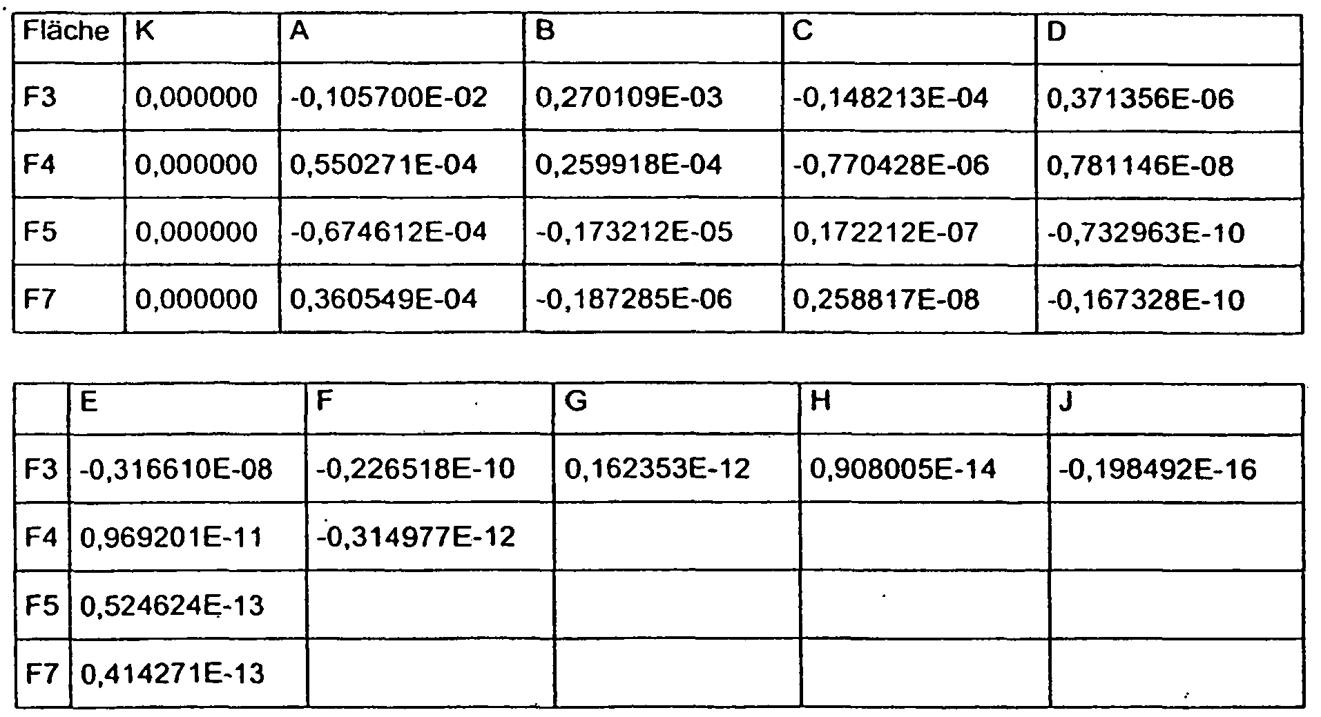
Fläche C1 λ0 [nm] Beugungsordnung N R1[mm] RN [mm] d [mm] F7 -2,2188 x 10⁻³ 546,07 1 579 0,4961 11,9374 0,001 -
Fläche Flächentyp Radius [mm] Abstand zur nächsten Fläche [mm] Material 9 unendlich 0,000000 F1 unendlich 0,900000 NBK7_SCHOTT F2 unendlich 3,120000 F3 asphärisch -6,37840 3,700000 PCARB F4 asphärisch -8,65554 2,150248 F5 asphärisch, diffraktiv 13,42553 17,500000 E48R F6 unendlich 16,500000 E48R F7 asphärisch -20,92638 18,300000 15 unendlich 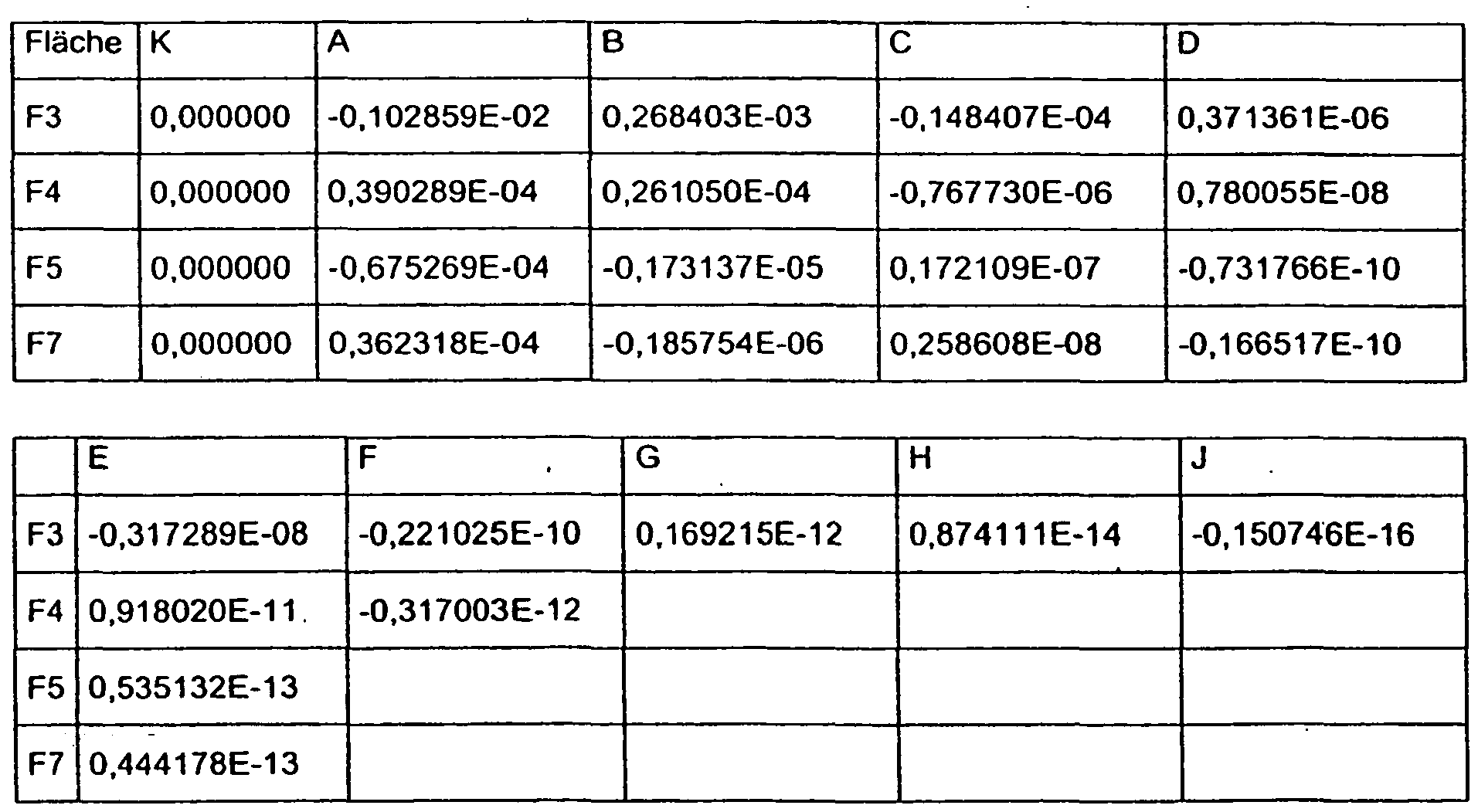
Fläche C1 λ0 [nm] Beugungsordnung N R1 [mm] RN [mm] d [mm] F7 -2,1824 x 10⁻³ 546,07 1 570 0,5002 11,9424 0,001 -
Fläche Flächentyp Radius [mm] Abstand zur nächsten Fläche [mm] Material 9 unendlich 0,000000 F1 unendlich 0,900000 NBK7_SCHOTT F2 unendlich 3,124979 F3 asphärisch -6,39073 3,700000 PSTYR F4 asphärisch -8,66860 2,100000 F5 asphärisch, diffraktiv 13,43194 17,500000 TOPAS F6 unendlich 16,500000 TOPAS F7 asphärisch -21,01111 18,300000 15 unendlich 
Fläche C1 λ0 [nm] Beugungsordnung N R1 [mm] RN [mm] d [mm] F7 -2,2154 x 10⁻³ 546,07 1 579 0,4965 11,9463 0,001 -
Fläche Flächentyp Radius [mm] Abstand zur nächsten Fläche [mm] Material 9 unendlich 0,000000 F1 unendlich 0,900000 NBK7_SCHOTT F2 unendlich 3,129602 F3 asphärisch -6,32866 3,700000 PCARB F4 asphärisch -8,60206 2,100000 F5 asphärisch, diffraktiv 13,43205 17,500000 TOPAS F6 unendlich 16,500000 TOPAS F7 asphärisch -21,00964 18,300000 15 unendlich 
Fläche C1 λ0 [nm] Beugungsordnung N R1 [mm] RN [mm] d [mm] F7 -2,2182 x 10⁻³ 546,07 1 579 0,4962 11,9389 0,001 -
Fläche Flächentyp Radius [mm] Abstand zur nächsten Fläche [mm] Material 9 unendlich 0,000000 F1 unendlich 0,900000 NBK7_SCHOTT F2 unendlich 3,524287 F3 asphärisch -6,21922 3,700000 PSTYR F4 asphärisch -9,29975 1,851370 F5 asphärisch, diffraktiv 14,11834 17,500000 E48R F6 unendlich 16,500000 E48R F7 asphärisch -20,64291 18,300000 15 unendlich 
Fläche C1 λ0 [nm] Beugungsordnung N R1 [mm] RN [mm] d [mm] F7 -2,2507 x 10⁻³ 546,07 1 588 0,4926 11,9440 0,001 -
Fläche Flächentyp Radius [mm] Abstand zur nächsten Fläche [mm] Material 9 unendlich 0,000000 F1 unendlich 0,900000 NBK7_SCHOTT F2 unendlich 3,034584 F3 asphärisch -5,79408 3,700000 PSTYR F4 asphärisch -11,092 4,6047 F5 asphärisch, diffraktiv 18,48583 17,0 E48R F6 unendlich 16,0 E48R F7 asphärisch -21,090 18,300000 15 unendlich 
Fläche C1 λ0 [nm] Beugungsordnung N R1 [mm] RN [mm] d [mm] F7 -1,6334 x 10⁻³ 546,07 1 465 0,5782 12,4683 0,001 -
Fläche Fiächentyp Radius [mm] Abstand zur nächsten Fläche [mm] Material 9 unendlich 0,000000 F1 unendlich 0,900000 NBK7_SCHOTT F2 unendlich 3,607542 F3 asphärisch -6,46993 3,700000 PSTYR F4 asphärisch -8,23353 2,100000 F5 asphärisch 12,82389 17,500000 480R F6 unendlich 16,500000 480R F7 asphärisch -21,79411 18,300000 15 unendlich 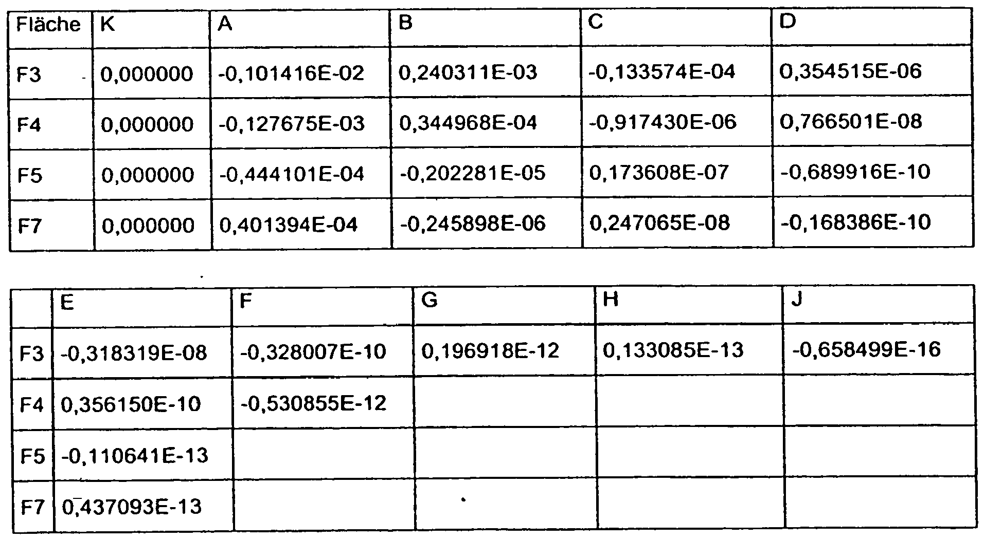
Claims (15)
- Optisches Okularsystem mit einem Bildelement (8) zum Erzeugen eines Bildes in einer Objektebene (9) und einer Abbildungsoptik (16), die das in der Objektebene (9) erzeugte Bild so abbildet, daß es ein Benutzer in einer Bildebene (15) wahrnehmen kann,
wobei die Abbildungsoptik (16) eine erste Linse (10) mit negativer Brechkraft und ein der ersten Linse (10) nachgeordnetes Umlenkelement (11) mit positiver Brechkraft, das eine Faltung des Strahlenganges mittels einer einzigen Reflexion bewirkt, umfaßt, wobei die der ersten Linse (10) zugewandte Grenzfläche (F5) des Umlenkelementes (11) konvex gekrümmt ist,
dadurch gekennzeichnet, daß
die erste Linse (10) und das Bildelement (8) eine erste Optikgruppe (19) bilden und eine Verschiebeeinheit (18) vorgesehen ist, die zur Korrektur einer sphärischen Fehlsichtigkeit des Benutzers den Abstand zwischen der ersten Optikgruppe (19) und dem Umlenkelement (11) ändern kann, wobei die dem Umlenkelement (11) zugewandte Grenzfläche (F4) der ersten Linse (10) konvex gekrümmt ist. - Okularsystem nach Anspruch 1, dadurch gekennzeichnet, daß die Verschiebeeinheit (18) die erste Optikgruppe (19) entlang der optischen Achse (OA) der Abbildungsoptik (16) verschieben kann.
- Okularsystem nach einem der obigen Ansprüche, dadurch gekennzeichnet, daß in der ersten Optikgruppe (19) der Abstand zwischen der ersten Linse (10) und der Objektebene (9) fixiert ist.
- Okularsystem nach einem der obigen Ansprüche, dadurch gekennzeichnet, daß das Umlenkelement (11) einstückig ausgebildet ist.
- Okularsystem nach einem der obigen Ansprüche, dadurch gekennzeichnet, daß beide Grenzflächen (F3, F4) der ersten Linse (10) sowie Eintritts- und Austrittsfläche (F5, F7) des Umlenkelementes (11) asphärisch gekrümmt sind, wobei die asphärischen Flächen rotationssymmetrisch und zur optischen Achse (OA) der Abbildungsoptik (16) zentriert sind.
- Okularsystem nach einem der obigen Ansprüche, dadurch gekennzeichnet, daß die der ersten Linse (10) zugewandte Grenzfläche (F5) des Umlenkelements (11) als diffraktive Fläche ausgebildet ist.
- Okularsystem nach einem der obigen Ansprüche, dadurch gekennzeichnet, daß das Umlenkelement (11) die Faltung des Strahlengangs um 70°- 110°, bevorzugt 90°bewirkt.
- Okularsystem nach einem der obigen Ansprüche, dadurch gekennzeichnet, daß die erste Linse-(-10)-und das-Bildelement (9) in einer einzigen Fassung (17) gehalten sind.
- Okularsystem nach einem der obigen Ansprüche, dadurch gekennzeichnet, daß die erste Linse (10) und das Bildelement (9) formschlüssig miteinander verbunden sind.
- Okularsystem nach einem der obigen Ansprüche, dadurch gekennzeichnet, daß die Abbildungsoptik (16) und das Bildelement (9) ein Augenmodul bilden, das zweimal für beide Augen des Benutzers vorgesehen ist.
- Okularsystem nach Anspruch 10, dadurch gekennzeichnet, daß der Abstand zwischen der Optikgruppe (19) und dem Umlenkelement (11) in beiden Augenmodulen voneinander unabhängig veränderbar ist.
- Okularsystem nach Anspruch 10 oder 11, dadurch gekennzeichnet, daß der Strahlengang im Augenmodul von der Bildebene (9) bis zur Austrittspupille (15) der Abbildungsoptik (16) im wesentlichen L-förmig ist, wobei die Augenmodule so angeordnet sind, daß der Abstand der beiden Optikgruppen (19) kleiner ist als der Abstand der beiden Umlenkelemente (11).
- Okularsystem nach Anspruch 10 oder 11, dadurch gekennzeichnet, daß der Strahlengang im Augenmodul von der Bildebene (9) bis zur Austrittspupille (15) der Abbildungsoptik (16) im wesentlichen L-förmig ist, wobei die Augenmodule so angeordnet sind, daß der Abstand der beiden Optikgruppen (19) größer ist als der Abstand der beiden Umlenkelemente (11).
- Anzeigevorrichtung mit einem optischen Okularsystem nach einem der obigen Ansprüche und einem auf dem Kopf zu tragenden Haltemodul (4), bei der die Abbildungsoptik (16) am Haltemodul (4) befestigt ist, wobei das mittels der Abbildungsoptik (16) abgebildete Bild von einem die Anzeigevorrichtung tragenden Benutzer wahrnehmbar ist.
- Anzeigevorrichtung nach Anspruch 14, bei der das Bildelement (9) am Haltemodul (4) befestigt ist.
Applications Claiming Priority (2)
| Application Number | Priority Date | Filing Date | Title |
|---|---|---|---|
| DE102007015278A DE102007015278A1 (de) | 2007-03-29 | 2007-03-29 | Optisches Okularsystem |
| PCT/EP2008/002487 WO2008119512A1 (de) | 2007-03-29 | 2008-03-28 | Optisches okularsystem |
Publications (2)
| Publication Number | Publication Date |
|---|---|
| EP2130083A1 EP2130083A1 (de) | 2009-12-09 |
| EP2130083B1 true EP2130083B1 (de) | 2012-03-07 |
Family
ID=39577899
Family Applications (1)
| Application Number | Title | Priority Date | Filing Date |
|---|---|---|---|
| EP08734859A Not-in-force EP2130083B1 (de) | 2007-03-29 | 2008-03-28 | Optisches okularsystem |
Country Status (5)
| Country | Link |
|---|---|
| US (1) | US7889429B2 (de) |
| EP (1) | EP2130083B1 (de) |
| AT (1) | ATE548672T1 (de) |
| DE (1) | DE102007015278A1 (de) |
| WO (1) | WO2008119512A1 (de) |
Families Citing this family (17)
| Publication number | Priority date | Publication date | Assignee | Title |
|---|---|---|---|---|
| JP6111635B2 (ja) * | 2012-02-24 | 2017-04-12 | セイコーエプソン株式会社 | 虚像表示装置 |
| DE102013207257B4 (de) * | 2013-04-22 | 2021-03-04 | Carl Zeiss Jena Gmbh | Anzeigevorrichtung |
| DE102014107938B4 (de) * | 2014-06-05 | 2020-08-06 | Carl Zeiss Ag | Anzeigevorrichtung |
| WO2016047427A1 (ja) * | 2014-09-24 | 2016-03-31 | コニカミノルタ株式会社 | プリズム、プリズムの製造方法、金型およびセンサーチップ |
| CN105511076A (zh) * | 2014-09-24 | 2016-04-20 | 广州南北电子科技有限公司 | 光学系统和视频眼镜 |
| CN105824121A (zh) * | 2015-01-06 | 2016-08-03 | 广州南北电子科技有限公司 | 一种光学系统和视频眼镜 |
| IL244255A (en) | 2016-02-23 | 2017-04-30 | Vertical Optics Llc | Wearable vision redirecting devices |
| US9690119B2 (en) | 2015-05-15 | 2017-06-27 | Vertical Optics, LLC | Wearable vision redirecting devices |
| WO2016187064A1 (en) | 2015-05-15 | 2016-11-24 | Vertical Optics, LLC | Wearable vision redirecting devices |
| WO2019075742A1 (zh) * | 2017-10-20 | 2019-04-25 | 北京耐德佳显示技术有限公司 | 一种超薄型增强现实用镜片、使用其的虚像成像装置和近眼显示器 |
| FR3082319B1 (fr) * | 2018-06-11 | 2021-12-17 | Ait Yahiatene Daniel | Objectif pour la focalisation d’images |
| JP7183610B2 (ja) * | 2018-07-30 | 2022-12-06 | セイコーエプソン株式会社 | 虚像表示装置 |
| CN111239973B (zh) * | 2020-03-12 | 2025-04-29 | 浙江舜宇光学有限公司 | 摄像光学镜头 |
| CN111766754B (zh) * | 2020-07-23 | 2021-09-17 | 歌尔光学科技有限公司 | 光学系统及投影装置 |
| CN111948823B (zh) * | 2020-08-21 | 2024-01-23 | 香港理工大学 | 一种可抑制近视加深的虚拟现实设备及其光路结构 |
| CN111929899A (zh) * | 2020-08-21 | 2020-11-13 | 香港理工大学 | 一种增强现实头戴显示设备 |
| CN117631277A (zh) * | 2022-08-16 | 2024-03-01 | 宏达国际电子股份有限公司 | 影像感测装置及头戴式显示装置 |
Family Cites Families (17)
| Publication number | Priority date | Publication date | Assignee | Title |
|---|---|---|---|---|
| US4923282A (en) | 1988-08-18 | 1990-05-08 | Spitzberg Larry A | Magnifying apparatus and method |
| US5095326A (en) | 1988-10-28 | 1992-03-10 | Asahi Kogaku Kogyo K.K. | Kepler-type erect image viewfinder and erecting prism |
| JPH06324285A (ja) * | 1993-05-13 | 1994-11-25 | Olympus Optical Co Ltd | 視覚表示装置 |
| US5793339A (en) * | 1993-11-11 | 1998-08-11 | Olympus Optical Co., Ltd. | Visual display apparatus |
| US5768025A (en) | 1995-08-21 | 1998-06-16 | Olympus Optical Co., Ltd. | Optical system and image display apparatus |
| US5959780A (en) | 1996-04-15 | 1999-09-28 | Olympus Optical Co., Ltd. | Head-mounted display apparatus comprising a rotationally asymmetric surface |
| JPH10123454A (ja) | 1996-10-16 | 1998-05-15 | Olympus Optical Co Ltd | 頭部装着型画像表示装置 |
| JP3865906B2 (ja) | 1997-06-27 | 2007-01-10 | オリンパス株式会社 | 画像表示装置 |
| US20010048561A1 (en) * | 2000-08-24 | 2001-12-06 | Heacock Gregory L. | Virtual imaging system for small font text |
| JP2003233007A (ja) * | 2002-02-07 | 2003-08-22 | Olympus Optical Co Ltd | ズーム光学系及びそれを用いた撮像装置 |
| JP2003233008A (ja) * | 2002-02-08 | 2003-08-22 | Olympus Optical Co Ltd | 撮像装置 |
| JP2004151552A (ja) | 2002-10-31 | 2004-05-27 | Olympus Corp | 薄型電子撮像装置用ズームレンズ |
| US6995922B2 (en) | 2003-01-10 | 2006-02-07 | Olympus Corporation | Zoom lens and electronic imaging apparatus having the same |
| JP4441188B2 (ja) | 2003-02-28 | 2010-03-31 | オリンパス株式会社 | 電子撮像装置 |
| EP1513000B8 (de) | 2003-09-03 | 2007-02-14 | Carl Zeiss | HMD-Vorrichtung (Head Mounted Display) mit einer eine asphärische Fläche aufweisenden Abbildungsoptik |
| JP2005084284A (ja) | 2003-09-08 | 2005-03-31 | Sony Corp | ビューファインダーおよび撮像装置 |
| DE102004020818A1 (de) | 2004-04-28 | 2005-11-24 | Carl Zeiss | Anzeigevorrichtung |
-
2007
- 2007-03-29 DE DE102007015278A patent/DE102007015278A1/de not_active Ceased
-
2008
- 2008-03-28 US US12/593,227 patent/US7889429B2/en active Active
- 2008-03-28 AT AT08734859T patent/ATE548672T1/de active
- 2008-03-28 WO PCT/EP2008/002487 patent/WO2008119512A1/de not_active Ceased
- 2008-03-28 EP EP08734859A patent/EP2130083B1/de not_active Not-in-force
Also Published As
| Publication number | Publication date |
|---|---|
| DE102007015278A1 (de) | 2008-10-02 |
| WO2008119512A1 (de) | 2008-10-09 |
| US7889429B2 (en) | 2011-02-15 |
| US20100128346A1 (en) | 2010-05-27 |
| EP2130083A1 (de) | 2009-12-09 |
| ATE548672T1 (de) | 2012-03-15 |
Similar Documents
| Publication | Publication Date | Title |
|---|---|---|
| EP2130083B1 (de) | Optisches okularsystem | |
| EP1513000B1 (de) | HMD-Vorrichtung (Head Mounted Display) mit einer eine asphärische Fläche aufweisenden Abbildungsoptik | |
| EP3072005B1 (de) | Abbildungsoptik sowie anzeigevorrichtung mit einer solchen abbildungsoptik | |
| EP2601553B1 (de) | Anzeigevorrichtung mit einer auf den kopf eines benutzers aufsetzbaren haltevorrichtung | |
| EP3353588B1 (de) | Anzeigevorrictung mit einer abbildungsoptik | |
| EP3391129B1 (de) | Ophthalmologisches optisches element und verfahren zum auslegen eines ophthalmologischen optischen elements | |
| DE102013219623B4 (de) | Brillenglas für eine auf den Kopf eines Benutzers aufsetzbare und ein Bild erzeugende Anzeigevorrichtung sowie Anzeigevorrichtung mit einem solchen Brillenglas | |
| DE102013223963A1 (de) | Abbildungsoptik sowie Anzeigevorrichtung mit einer solchen Abbildungsoptik | |
| DE102014207499A1 (de) | Brillenglas für eine auf den Kopf eines Benutzers aufsetzbare und ein Bild erzeugende Anzeigevorrichtung | |
| DE102015122131B3 (de) | Brillenglas für eine auf den Kopf eines Benutzers aufsetzbare und ein Bild erzeugende Anzeigevorrichtung sowie Anzeigevorrichtung mit einem solchen Brillenglas | |
| DE102007004444A1 (de) | Multifunktionsglas | |
| DE112022006646T5 (de) | Brillenglas zur Verringerung des Fortschreitens der Myopie | |
| DE102014119550A1 (de) | Abbildungsoptik zum Erzeugen eines virtuellen Bildes und Datenbrille | |
| DE102014107938A1 (de) | Anzeigevorrichtung | |
| DE102007046505B4 (de) | Anzeigevorrichtung und Stereo-Anzeigemodul | |
| EP3574368A1 (de) | Brillenglas für eine auf den kopf eines benutzers aufsetzbare und ein bild erzeugende anzeigevorrichtung | |
| DE102009045128B4 (de) | Anzeigevorrichtung | |
| DE102007044228A1 (de) | Optische Einrichtung | |
| DE102007036974B4 (de) | HMD-Vorrichtung | |
| DE102007046711B4 (de) | Anzeigevorrichtung | |
| DE102004020818A1 (de) | Anzeigevorrichtung | |
| DE102019211360A1 (de) | Tubussystem | |
| DE202005021014U1 (de) | HMD-Vorrichtung | |
| DE102023111103A1 (de) | Optisches system mit für erweiterte realitätsanwendungen angepasster fresnellinse | |
| DE102020134017A1 (de) | Optisches System |
Legal Events
| Date | Code | Title | Description |
|---|---|---|---|
| PUAI | Public reference made under article 153(3) epc to a published international application that has entered the european phase |
Free format text: ORIGINAL CODE: 0009012 |
|
| 17P | Request for examination filed |
Effective date: 20090908 |
|
| AK | Designated contracting states |
Kind code of ref document: A1 Designated state(s): AT BE BG CH CY CZ DE DK EE ES FI FR GB GR HR HU IE IS IT LI LT LU LV MC MT NL NO PL PT RO SE SI SK TR |
|
| DAX | Request for extension of the european patent (deleted) | ||
| GRAP | Despatch of communication of intention to grant a patent |
Free format text: ORIGINAL CODE: EPIDOSNIGR1 |
|
| GRAS | Grant fee paid |
Free format text: ORIGINAL CODE: EPIDOSNIGR3 |
|
| GRAA | (expected) grant |
Free format text: ORIGINAL CODE: 0009210 |
|
| AK | Designated contracting states |
Kind code of ref document: B1 Designated state(s): AT BE BG CH CY CZ DE DK EE ES FI FR GB GR HR HU IE IS IT LI LT LU LV MC MT NL NO PL PT RO SE SI SK TR |
|
| REG | Reference to a national code |
Ref country code: GB Ref legal event code: FG4D Free format text: NOT ENGLISH |
|
| REG | Reference to a national code |
Ref country code: CH Ref legal event code: NV Representative=s name: KELLER & PARTNER PATENTANWAELTE AG Ref country code: CH Ref legal event code: EP Ref country code: AT Ref legal event code: REF Ref document number: 548672 Country of ref document: AT Kind code of ref document: T Effective date: 20120315 |
|
| REG | Reference to a national code |
Ref country code: IE Ref legal event code: FG4D Free format text: LANGUAGE OF EP DOCUMENT: GERMAN |
|
| REG | Reference to a national code |
Ref country code: DE Ref legal event code: R096 Ref document number: 502008006618 Country of ref document: DE Effective date: 20120503 |
|
| REG | Reference to a national code |
Ref country code: NL Ref legal event code: VDEP Effective date: 20120307 |
|
| PG25 | Lapsed in a contracting state [announced via postgrant information from national office to epo] |
Ref country code: NL Free format text: LAPSE BECAUSE OF FAILURE TO SUBMIT A TRANSLATION OF THE DESCRIPTION OR TO PAY THE FEE WITHIN THE PRESCRIBED TIME-LIMIT Effective date: 20120307 Ref country code: NO Free format text: LAPSE BECAUSE OF FAILURE TO SUBMIT A TRANSLATION OF THE DESCRIPTION OR TO PAY THE FEE WITHIN THE PRESCRIBED TIME-LIMIT Effective date: 20120607 Ref country code: HR Free format text: LAPSE BECAUSE OF FAILURE TO SUBMIT A TRANSLATION OF THE DESCRIPTION OR TO PAY THE FEE WITHIN THE PRESCRIBED TIME-LIMIT Effective date: 20120307 Ref country code: LT Free format text: LAPSE BECAUSE OF FAILURE TO SUBMIT A TRANSLATION OF THE DESCRIPTION OR TO PAY THE FEE WITHIN THE PRESCRIBED TIME-LIMIT Effective date: 20120307 |
|
| LTIE | Lt: invalidation of european patent or patent extension |
Effective date: 20120307 |
|
| PG25 | Lapsed in a contracting state [announced via postgrant information from national office to epo] |
Ref country code: FI Free format text: LAPSE BECAUSE OF FAILURE TO SUBMIT A TRANSLATION OF THE DESCRIPTION OR TO PAY THE FEE WITHIN THE PRESCRIBED TIME-LIMIT Effective date: 20120307 Ref country code: GR Free format text: LAPSE BECAUSE OF FAILURE TO SUBMIT A TRANSLATION OF THE DESCRIPTION OR TO PAY THE FEE WITHIN THE PRESCRIBED TIME-LIMIT Effective date: 20120608 Ref country code: LV Free format text: LAPSE BECAUSE OF FAILURE TO SUBMIT A TRANSLATION OF THE DESCRIPTION OR TO PAY THE FEE WITHIN THE PRESCRIBED TIME-LIMIT Effective date: 20120307 |
|
| PG25 | Lapsed in a contracting state [announced via postgrant information from national office to epo] |
Ref country code: CY Free format text: LAPSE BECAUSE OF FAILURE TO SUBMIT A TRANSLATION OF THE DESCRIPTION OR TO PAY THE FEE WITHIN THE PRESCRIBED TIME-LIMIT Effective date: 20120307 |
|
| BERE | Be: lapsed |
Owner name: CARL ZEISS A.G. Effective date: 20120331 |
|
| PG25 | Lapsed in a contracting state [announced via postgrant information from national office to epo] |
Ref country code: EE Free format text: LAPSE BECAUSE OF FAILURE TO SUBMIT A TRANSLATION OF THE DESCRIPTION OR TO PAY THE FEE WITHIN THE PRESCRIBED TIME-LIMIT Effective date: 20120307 Ref country code: RO Free format text: LAPSE BECAUSE OF FAILURE TO SUBMIT A TRANSLATION OF THE DESCRIPTION OR TO PAY THE FEE WITHIN THE PRESCRIBED TIME-LIMIT Effective date: 20120307 Ref country code: IS Free format text: LAPSE BECAUSE OF FAILURE TO SUBMIT A TRANSLATION OF THE DESCRIPTION OR TO PAY THE FEE WITHIN THE PRESCRIBED TIME-LIMIT Effective date: 20120707 Ref country code: MC Free format text: LAPSE BECAUSE OF NON-PAYMENT OF DUE FEES Effective date: 20120331 Ref country code: SI Free format text: LAPSE BECAUSE OF FAILURE TO SUBMIT A TRANSLATION OF THE DESCRIPTION OR TO PAY THE FEE WITHIN THE PRESCRIBED TIME-LIMIT Effective date: 20120307 Ref country code: SE Free format text: LAPSE BECAUSE OF FAILURE TO SUBMIT A TRANSLATION OF THE DESCRIPTION OR TO PAY THE FEE WITHIN THE PRESCRIBED TIME-LIMIT Effective date: 20120307 Ref country code: PL Free format text: LAPSE BECAUSE OF FAILURE TO SUBMIT A TRANSLATION OF THE DESCRIPTION OR TO PAY THE FEE WITHIN THE PRESCRIBED TIME-LIMIT Effective date: 20120307 Ref country code: CZ Free format text: LAPSE BECAUSE OF FAILURE TO SUBMIT A TRANSLATION OF THE DESCRIPTION OR TO PAY THE FEE WITHIN THE PRESCRIBED TIME-LIMIT Effective date: 20120307 |
|
| PG25 | Lapsed in a contracting state [announced via postgrant information from national office to epo] |
Ref country code: SK Free format text: LAPSE BECAUSE OF FAILURE TO SUBMIT A TRANSLATION OF THE DESCRIPTION OR TO PAY THE FEE WITHIN THE PRESCRIBED TIME-LIMIT Effective date: 20120307 Ref country code: PT Free format text: LAPSE BECAUSE OF FAILURE TO SUBMIT A TRANSLATION OF THE DESCRIPTION OR TO PAY THE FEE WITHIN THE PRESCRIBED TIME-LIMIT Effective date: 20120709 |
|
| REG | Reference to a national code |
Ref country code: IE Ref legal event code: MM4A |
|
| PLBE | No opposition filed within time limit |
Free format text: ORIGINAL CODE: 0009261 |
|
| STAA | Information on the status of an ep patent application or granted ep patent |
Free format text: STATUS: NO OPPOSITION FILED WITHIN TIME LIMIT |
|
| PG25 | Lapsed in a contracting state [announced via postgrant information from national office to epo] |
Ref country code: DK Free format text: LAPSE BECAUSE OF FAILURE TO SUBMIT A TRANSLATION OF THE DESCRIPTION OR TO PAY THE FEE WITHIN THE PRESCRIBED TIME-LIMIT Effective date: 20120307 Ref country code: IE Free format text: LAPSE BECAUSE OF NON-PAYMENT OF DUE FEES Effective date: 20120328 Ref country code: BE Free format text: LAPSE BECAUSE OF NON-PAYMENT OF DUE FEES Effective date: 20120331 |
|
| 26N | No opposition filed |
Effective date: 20121210 |
|
| REG | Reference to a national code |
Ref country code: DE Ref legal event code: R097 Ref document number: 502008006618 Country of ref document: DE Effective date: 20121210 |
|
| PG25 | Lapsed in a contracting state [announced via postgrant information from national office to epo] |
Ref country code: ES Free format text: LAPSE BECAUSE OF FAILURE TO SUBMIT A TRANSLATION OF THE DESCRIPTION OR TO PAY THE FEE WITHIN THE PRESCRIBED TIME-LIMIT Effective date: 20120618 |
|
| PG25 | Lapsed in a contracting state [announced via postgrant information from national office to epo] |
Ref country code: MT Free format text: LAPSE BECAUSE OF FAILURE TO SUBMIT A TRANSLATION OF THE DESCRIPTION OR TO PAY THE FEE WITHIN THE PRESCRIBED TIME-LIMIT Effective date: 20120307 Ref country code: BG Free format text: LAPSE BECAUSE OF FAILURE TO SUBMIT A TRANSLATION OF THE DESCRIPTION OR TO PAY THE FEE WITHIN THE PRESCRIBED TIME-LIMIT Effective date: 20120607 |
|
| PG25 | Lapsed in a contracting state [announced via postgrant information from national office to epo] |
Ref country code: TR Free format text: LAPSE BECAUSE OF FAILURE TO SUBMIT A TRANSLATION OF THE DESCRIPTION OR TO PAY THE FEE WITHIN THE PRESCRIBED TIME-LIMIT Effective date: 20120307 |
|
| PG25 | Lapsed in a contracting state [announced via postgrant information from national office to epo] |
Ref country code: LU Free format text: LAPSE BECAUSE OF NON-PAYMENT OF DUE FEES Effective date: 20120328 |
|
| PG25 | Lapsed in a contracting state [announced via postgrant information from national office to epo] |
Ref country code: HU Free format text: LAPSE BECAUSE OF FAILURE TO SUBMIT A TRANSLATION OF THE DESCRIPTION OR TO PAY THE FEE WITHIN THE PRESCRIBED TIME-LIMIT Effective date: 20080328 |
|
| REG | Reference to a national code |
Ref country code: CH Ref legal event code: PCAR Free format text: NEW ADDRESS: EIGERSTRASSE 2 POSTFACH, 3000 BERN 14 (CH) |
|
| REG | Reference to a national code |
Ref country code: FR Ref legal event code: PLFP Year of fee payment: 9 |
|
| REG | Reference to a national code |
Ref country code: FR Ref legal event code: PLFP Year of fee payment: 10 |
|
| REG | Reference to a national code |
Ref country code: FR Ref legal event code: PLFP Year of fee payment: 11 |
|
| REG | Reference to a national code |
Ref country code: CH Ref legal event code: PFA Owner name: CARL ZEISS AG, DE Free format text: FORMER OWNER: CARL ZEISS AG, DE |
|
| PGFP | Annual fee paid to national office [announced via postgrant information from national office to epo] |
Ref country code: GB Payment date: 20220321 Year of fee payment: 15 Ref country code: DE Payment date: 20220322 Year of fee payment: 15 Ref country code: CH Payment date: 20220321 Year of fee payment: 15 Ref country code: AT Payment date: 20220322 Year of fee payment: 15 |
|
| PGFP | Annual fee paid to national office [announced via postgrant information from national office to epo] |
Ref country code: IT Payment date: 20220322 Year of fee payment: 15 Ref country code: FR Payment date: 20220322 Year of fee payment: 15 |
|
| REG | Reference to a national code |
Ref country code: DE Ref legal event code: R119 Ref document number: 502008006618 Country of ref document: DE |
|
| REG | Reference to a national code |
Ref country code: CH Ref legal event code: PL |
|
| REG | Reference to a national code |
Ref country code: AT Ref legal event code: MM01 Ref document number: 548672 Country of ref document: AT Kind code of ref document: T Effective date: 20230328 |
|
| GBPC | Gb: european patent ceased through non-payment of renewal fee |
Effective date: 20230328 |
|
| PG25 | Lapsed in a contracting state [announced via postgrant information from national office to epo] |
Ref country code: GB Free format text: LAPSE BECAUSE OF NON-PAYMENT OF DUE FEES Effective date: 20230328 |
|
| PG25 | Lapsed in a contracting state [announced via postgrant information from national office to epo] |
Ref country code: LI Free format text: LAPSE BECAUSE OF NON-PAYMENT OF DUE FEES Effective date: 20230331 Ref country code: GB Free format text: LAPSE BECAUSE OF NON-PAYMENT OF DUE FEES Effective date: 20230328 Ref country code: FR Free format text: LAPSE BECAUSE OF NON-PAYMENT OF DUE FEES Effective date: 20230331 Ref country code: DE Free format text: LAPSE BECAUSE OF NON-PAYMENT OF DUE FEES Effective date: 20231003 Ref country code: CH Free format text: LAPSE BECAUSE OF NON-PAYMENT OF DUE FEES Effective date: 20230331 Ref country code: AT Free format text: LAPSE BECAUSE OF NON-PAYMENT OF DUE FEES Effective date: 20230328 |
|
| PG25 | Lapsed in a contracting state [announced via postgrant information from national office to epo] |
Ref country code: IT Free format text: LAPSE BECAUSE OF NON-PAYMENT OF DUE FEES Effective date: 20230328 |