EP2130266B1 - Antenne mit einem resonator mit einer filterungsbeschichtung und system mit einer solchen antenne - Google Patents
Antenne mit einem resonator mit einer filterungsbeschichtung und system mit einer solchen antenne Download PDFInfo
- Publication number
- EP2130266B1 EP2130266B1 EP08787987A EP08787987A EP2130266B1 EP 2130266 B1 EP2130266 B1 EP 2130266B1 EP 08787987 A EP08787987 A EP 08787987A EP 08787987 A EP08787987 A EP 08787987A EP 2130266 B1 EP2130266 B1 EP 2130266B1
- Authority
- EP
- European Patent Office
- Prior art keywords
- frequency
- electromagnetic waves
- reflector
- wall
- antenna
- Prior art date
- Legal status (The legal status is an assumption and is not a legal conclusion. Google has not performed a legal analysis and makes no representation as to the accuracy of the status listed.)
- Not-in-force
Links
- 239000011248 coating agent Substances 0.000 title claims abstract description 55
- 238000000576 coating method Methods 0.000 title claims abstract description 55
- 238000001914 filtration Methods 0.000 title claims abstract description 22
- 239000000463 material Substances 0.000 claims description 75
- 239000000523 sample Substances 0.000 claims description 47
- 230000005284 excitation Effects 0.000 claims description 46
- 230000005672 electromagnetic field Effects 0.000 claims description 14
- 238000002347 injection Methods 0.000 claims description 10
- 239000007924 injection Substances 0.000 claims description 10
- 230000000644 propagated effect Effects 0.000 claims description 7
- 230000010363 phase shift Effects 0.000 claims description 6
- 230000035699 permeability Effects 0.000 claims description 5
- 230000015572 biosynthetic process Effects 0.000 claims description 3
- 238000009826 distribution Methods 0.000 claims description 3
- 230000007423 decrease Effects 0.000 claims 1
- 239000000126 substance Substances 0.000 claims 1
- 230000001902 propagating effect Effects 0.000 abstract description 22
- 238000011049 filling Methods 0.000 description 14
- 230000005855 radiation Effects 0.000 description 11
- 238000002310 reflectometry Methods 0.000 description 8
- 239000002184 metal Substances 0.000 description 7
- 229910052751 metal Inorganic materials 0.000 description 7
- 230000010287 polarization Effects 0.000 description 7
- 239000006185 dispersion Substances 0.000 description 6
- 230000005291 magnetic effect Effects 0.000 description 6
- 238000010586 diagram Methods 0.000 description 5
- 238000013461 design Methods 0.000 description 4
- 238000004458 analytical method Methods 0.000 description 2
- 230000001976 improved effect Effects 0.000 description 2
- 101100536354 Drosophila melanogaster tant gene Proteins 0.000 description 1
- PNEYBMLMFCGWSK-UHFFFAOYSA-N aluminium oxide Inorganic materials [O-2].[O-2].[O-2].[Al+3].[Al+3] PNEYBMLMFCGWSK-UHFFFAOYSA-N 0.000 description 1
- 230000003416 augmentation Effects 0.000 description 1
- 230000008859 change Effects 0.000 description 1
- 238000004891 communication Methods 0.000 description 1
- 230000006854 communication Effects 0.000 description 1
- 230000008878 coupling Effects 0.000 description 1
- 238000010168 coupling process Methods 0.000 description 1
- 238000005859 coupling reaction Methods 0.000 description 1
- 230000000694 effects Effects 0.000 description 1
- 230000005684 electric field Effects 0.000 description 1
- 239000006260 foam Substances 0.000 description 1
- 230000006872 improvement Effects 0.000 description 1
- 230000002452 interceptive effect Effects 0.000 description 1
- 239000007769 metal material Substances 0.000 description 1
- 239000003607 modifier Substances 0.000 description 1
- 230000000051 modifying effect Effects 0.000 description 1
- 230000000737 periodic effect Effects 0.000 description 1
- 230000001603 reducing effect Effects 0.000 description 1
Images




Classifications
-
- H—ELECTRICITY
- H01—ELECTRIC ELEMENTS
- H01P—WAVEGUIDES; RESONATORS, LINES, OR OTHER DEVICES OF THE WAVEGUIDE TYPE
- H01P1/00—Auxiliary devices
- H01P1/20—Frequency-selective devices, e.g. filters
- H01P1/2005—Electromagnetic photonic bandgaps [EPB], or photonic bandgaps [PBG]
-
- H—ELECTRICITY
- H01—ELECTRIC ELEMENTS
- H01Q—ANTENNAS, i.e. RADIO AERIALS
- H01Q15/00—Devices for reflection, refraction, diffraction or polarisation of waves radiated from an antenna, e.g. quasi-optical devices
- H01Q15/0006—Devices acting selectively as reflecting surface, as diffracting or as refracting device, e.g. frequency filtering or angular spatial filtering devices
- H01Q15/006—Selective devices having photonic band gap materials or materials of which the material properties are frequency dependent, e.g. perforated substrates, high-impedance surfaces
-
- H—ELECTRICITY
- H01—ELECTRIC ELEMENTS
- H01Q—ANTENNAS, i.e. RADIO AERIALS
- H01Q15/00—Devices for reflection, refraction, diffraction or polarisation of waves radiated from an antenna, e.g. quasi-optical devices
- H01Q15/0006—Devices acting selectively as reflecting surface, as diffracting or as refracting device, e.g. frequency filtering or angular spatial filtering devices
- H01Q15/006—Selective devices having photonic band gap materials or materials of which the material properties are frequency dependent, e.g. perforated substrates, high-impedance surfaces
- H01Q15/0073—Selective devices having photonic band gap materials or materials of which the material properties are frequency dependent, e.g. perforated substrates, high-impedance surfaces said selective devices having corrugations
-
- H—ELECTRICITY
- H01—ELECTRIC ELEMENTS
- H01Q—ANTENNAS, i.e. RADIO AERIALS
- H01Q19/00—Combinations of primary active antenna elements and units with secondary devices, e.g. with quasi-optical devices, for giving the antenna a desired directional characteristic
- H01Q19/10—Combinations of primary active antenna elements and units with secondary devices, e.g. with quasi-optical devices, for giving the antenna a desired directional characteristic using reflecting surfaces
- H01Q19/12—Combinations of primary active antenna elements and units with secondary devices, e.g. with quasi-optical devices, for giving the antenna a desired directional characteristic using reflecting surfaces wherein the surfaces are concave
- H01Q19/17—Combinations of primary active antenna elements and units with secondary devices, e.g. with quasi-optical devices, for giving the antenna a desired directional characteristic using reflecting surfaces wherein the surfaces are concave the primary radiating source comprising two or more radiating elements
Definitions
- the present invention relates to a resonator antenna equipped with a filter coating and a system incorporating this antenna.
- antennas are described in the particular case of antennas BIP material (Banding Prohibited Photonics) failing in the patent applications filed under the numbers FR 99 14521 and FR 2 801 428 A .
- These antennas have a small footprint and a strong directivity.
- the radiation pattern of these antennas thus has an important main lobe and secondary lobes.
- the invention aims to reduce the size and size of the side lobes.
- the first resonator comprises a filter coating covering the majority of the upper face of the reflector located inside the cavity, this coating being adapted to eliminate any electromagnetic waves of frequency f T propagating in a direction parallel to the upper face of the reflector without eliminating any electromagnetic waves at the frequency f T propagating in a direction perpendicular to the upper face of the reflector.
- the coating prevents the establishment of a guided mode in a direction parallel to the reflector. This results in a significant improvement in the performance of the antenna.
- the use of the claimed antenna increases the efficiency of this system by illuminating the largest possible area of the focusing device while reducing overflow losses beyond the contour of this device. of focus.
- the figure 1 represents a plane wave guide 2 and the figure 2 represents the scatter plot in this guide 2.
- the Figures 1 and 2 are known and are introduced here only to recall the definition of certain technical terms.
- the guide 2 is formed of a reflective plane 4 extending parallel to a horizontal XY plane, defined by two orthogonal directions X and Y.
- the plane 4 reflects 100% of the electromagnetic waves at the frequency f T which propagate perpendicular to its area.
- the plane 4 is made of metal.
- Z is the direction perpendicular to the X and Y directions.
- a horizontal wall 6 partially reflecting.
- partially reflecting means a wall that reflects strictly less than 100% and more than 80% of electromagnetic waves of frequency f T propagating perpendicularly to one of the horizontal faces of this wall 6.
- the wall 6 is separated from the reflector 4 by a space 8 of constant height h. This space is, for example, filled with air.
- the height h is measured in the Z direction.
- a wavy arrow 10 represents a guided electromagnetic wave propagating in the space 8.
- the propagation direction of the waves is parallel to the direction Y.
- the dotted arrows 11 represent the electromagnetic waves that leak the space 8 through the wall 6 which is only partially reflective.
- transverse dimensions that is to say perpendicular to the direction of propagation, are assumed to be infinite in the case of a plane waveguide.
- the figure 2 represents the dispersion diagram of the waveguide 2.
- the constant ⁇ represents the propagation constant of a mode propagating parallel to the reflector 4.
- the ordinate axis represents the frequency of the electromagnetic wave propagating in space 8.
- a plane waveguide In a plane waveguide, only certain propagation modes can be established according to the frequency of the wave to be propagated. These propagation modes are conventionally known in the terminology of TEM mode, (Magnetic Electric Transverse) of mode TE n (Electric Transverse of order n) and TM n (Magnetic Transverse of order n), where n is an integer greater than or equal to zero.
- TEM mode Magnetic Electric Transverse
- TE n Electrom Transverse of order n
- TM n Magnetic Transverse of order n
- a straight line 12 passing through the origin represents the value of the constant ⁇ for each frequency of the guided wave in the case where the propagation mode is the TEM mode.
- a curve 14 represents the value of the constant ⁇ for each possible frequency of the guided wave in the case where the propagation mode is the TE 1 or TM 1 mode.
- the curve 14 intersects the axis of frequencies for a frequency f c known under the term "cutoff frequency".
- the guided wave can propagate within the space 8 only according to the TEM mode.
- the guided wave in the space 8 can propagate according to the TEM, TE 1 or TM 1 mode.
- evanescent modes are characterized by the fact that the amplitude of the guided wave decreases very rapidly in the direction of propagation so that this wave can not propagate over a distance greater than 2 ⁇ where ⁇ is the wavelength of the electromagnetic wave of frequency f T in the material filling the space 8.
- the evanescent modes of the guide 2 correspond to modes of operation for which a maximum of electromagnetic energy is dissipated in the form of radiation in space after having passed through the wall 6.
- the reflective plane 22 is chosen to reflect 100% of the electromagnetic waves of frequency f T which propagate perpendicularly to this plane.
- the reflective plane 22 is made of metal and can be connected to a reference potential such as ground.
- Wall 24 is here designed to reflect strictly less than 100% and more than 80% of electromagnetic waves of frequency f T propagating in a direction perpendicular to this wall.
- the wall 24 is a BIP material.
- the BIP materials have a broad non-conducting band B. When an electromagnetic wave whose frequency is included in the non-conducting band B strikes this BIP material, it is almost completely reflected.
- the material forming the wall 24 is thus chosen so that the working frequency f T is included in the non-conducting band of this BIP material.
- the BIP material forming the wall 24 presents at least one periodic alternation of two materials in the direction Z.
- the wall 24 is formed by the superposition in the Z direction of three plane layers 26, 28 and 30.
- the layers 26 and 30 differ from each other. the layer 28 by their permittivity.
- the layers 26 and 30 are made of alumina while the layer 26 is a layer of air.
- the dimensions of these layers in the X and Y directions are chosen several times greater than the wavelength ⁇ a , where ⁇ a is the wavelength of the electromagnetic waves of frequency f T in the air.
- the lateral dimensions of the layers 26, 28 and 30 are chosen greater than four times ⁇ a .
- the wall 24 thus has a lower face 32 facing the reflector plane 22 and an upper face 34 opposite the lower face 32.
- the lower face 32 is spaced from the reflector 22 by a constant height h 1 .
- the space thus formed between the lower face 32 and the upper face of the reflector 22 forms a cavity 36.
- An excitation probe 38 is disposed inside the cavity 36 on the reflector 22 or in the plane of the reflector 22. In the XY plane, the probe 38 is disposed substantially in the middle of the cavity 36. This probe is suitable receiving or injecting into the cavity 36, at the reflector 22, electromagnetic fields at the frequency f T.
- the antenna 20 comprises a filter coating 40 covering the entire upper face of the reflector 22 which is located inside the cavity 36.
- the coating 40 thus surrounds the probe 38 without covering it.
- This coating 40 is made of a material adapted to prevent the propagation of electromagnetic waves of frequency f T in a direction parallel to the XY plane while allowing the propagation of these same waves in the Z direction.
- the coating 40 is made of a BIP material having a periodicity in two non-collinear directions of the XY plane.
- the periodicity of a BIP material in one direction is, for example, defined in the patent application filed under the number FR 99 14521 .
- the coating 40 has a periodicity in the X direction and a periodicity in the Y direction.
- the coating 40 is formed of vertical studs 42 arranged at regular intervals p in the X and Y directions. These studs 42 are made of the same material as that used for the reflector 22, that is to say say here in metal. Another material forming the coating 40 fills all the intervals between the pads 42. This other material is here air, that is to say a material identical to that filling the cavity 36.
- the length of the interval p is chosen as a function of the wavelength ⁇ a so as to filter the electromagnetic waves of frequency f T propagating in the X and Y directions.
- the length of the interval p is less than ⁇ a / 2 and preferably between ⁇ a / 4 and ⁇ a / 2.
- the height h p of the pads 42 in the Z direction must be strictly less than the height h 1 .
- the height h p is chosen strictly less than ⁇ a / 2 and preferably equal to ⁇ a / 4 plus or minus 15%.
- the pads 42 have a cross section, that is to say a section parallel to the XY plane, square.
- the largest width of this cross section is chosen less than ⁇ a / 8.
- the height h 1 is chosen using relation (1) so that the cutoff frequency f c is equal to or slightly greater than the frequency f T. Typically, it is arranged here that the ratio of the frequency f T on the frequency f c is between 0.85 and 1.
- the figure 4 represents the scatter plot of the antenna 20.
- curves 50 and 52 represent the frequency of the guided wave, respectively, according to the TEM mode and the TE 1 or TM 1 modes as a function of the propagation constant ⁇ .
- the curve 50 tends to an asymptotic value C represented by a horizontal line 54 in dashed lines as the constant ⁇ increases. This asymptotic value C is independent of the height h 1 .
- the height h 1 of the cavity 36 is chosen so that the frequency f T is between the frequency f c and the value C. Under these conditions, it is understood that no guided mode can be established at the interior of the cavity 36 when it is excited by a magnetic field of frequency f T. Thus, only evanescent modes appear and the energy of the electromagnetic field introduced by the probe 38 into the cavity 36 dissipates almost exclusively in the form of radiation after passing through the wall 24. This results in an increase in the directivity of the antenna 20 with respect to an identical antenna but devoid of a filtering coating such as the coating 40.
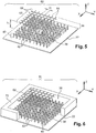
- the figure 5 represents an antenna 60 identical to the antenna 20 except that the wall 24 is replaced by a partially reflecting wall 62.
- the wall 62 is here not made using a BIP material but using a grid 62 formed of metal rods extending parallel to each other in a plane parallel to the XY plane. More specifically, here, the grid 62 comprises on the one hand bars 66 arranged at regular intervals m and all extending parallel to the direction X and on the other hand bars 68 arranged parallel to each other in the direction Y to regular intervals m .
- the length of the interval m is chosen strictly less than ⁇ a / 2 so that this grid 62 partially reflects the electromagnetic waves of frequency f T propagating in the direction Z.
- m is less than ⁇ a / 4.
- the height h 1 of the cavity 36 is chosen so that the cutoff frequency f c is slightly greater than the frequency f T. Under these conditions, the operation of the antenna 60 is similar to that of the antenna 20.
- the figure 6 represents an antenna 70 identical to the antenna 60 except that the cavity 36 is isolated from the outside of the antenna by side walls 72. figure 6 only part of the wall 72 completely surrounding the cavity 36 has been shown so as to leave visible the interior of the cavity 36.
- the wall 72 extends in the direction Z from the reflector 22 to the underside of the grid 62.
- the wall 72 is, for example, made here, in a metallic material reflecting all the electromagnetic waves of frequency f T .
- the figure 7 is an antenna 80 identical to the antenna 70 except that the grid 62 is replaced by a grid 82.
- the grid 82 is identical to the grid 62 except that the bars 68 have been omitted.
- Such a grid 82 constitutes a partially reflecting wall only for electromagnetic waves of frequency f T having a given polarization.
- the grid 82 constitutes a transparent wall which does not or hardly reflect the electromagnetic waves of frequency f T of different polarization.
- the grid 82 makes it possible to exert a polarization filtering on the transmitted or received waves.
- the figure 9 represents two curves 100 and 102 corresponding to the evolution of the directivity, respectively, of the antennas 60 and 70 as a function of the frequency f T.
- the figure 9 also represents a curve 104 indicating the evolution of the directivity of an antenna identical to the antenna 60 but devoid of the filtering coating 40.
- the abscissa represents the ratio of the frequency f T to the cutoff frequency f c .
- the y-axis represents the maximum directivity expressed in decibels (dB).
- the curves 100, 102 and 104 were obtained using an identical probe, that is to say here, a slot formed in the plane of the reflector 22 and through which is introduced the electromagnetic field of frequency f T in the cavity 36.
- the directivity of the antennas 60 and 70 is systematically improved when the frequency f T is lower than the frequency f c .
- the Figures 10 and 11 represent the radiation patterns, respectively, in the planes E and H of an antenna identical to the antenna 60 but devoid of the filtering coating 40.
- the Figures 12 and 13 represent the radiation patterns, respectively, in the planes E and H of the antenna 60 in the particular case where the ratio of the frequency f T on the frequency f c is equal to 0.997.
- Figures 14 and 15 represent the radiation patterns, respectively, in the planes E and H of the antenna 70 in the particular case where the ratio of the frequency f T on the frequency f c is equal to 1.007.
- the presence of the filter coating can significantly attenuate the side lobes of the antenna.
- the antenna has been formed of a single resonator. However, it may be particularly interesting to superpose two resonators so as to create a multibeam antenna in which the radiating tasks partially overlap. Such an antenna 120 is shown on the figure 16 .
- the antenna 120 is formed of a first resonator 122 on which is superimposed a second resonator 123.
- the resonator 122 is, for example, identical to any of the resonators of the antennas 20, 60, 70, 80 or 90 except that it comprises several excitation probes.
- the resonator 122 is therefore identical to that of the antenna 20 in which the probe 38 is replaced by five excitation probes 124 to 128.
- the probes 124 to 128 are here chosen so that they form a surface for injecting or receiving electromagnetic fields inside the cavity 36.
- the largest width of each of the injection or reception is greater than or equal to ⁇ a .
- the distribution of the power of the electromagnetic field on the injection or reception surface has a point where the power is maximum, this point being away from the periphery of this injection surface.
- the power of the electromagnetic field of this injection surface is distributed such that the power decreases continuously along any straight line from the point where the power is maximum to the periphery of this surface.
- a probe having such an injection surface makes it possible to increase the directivity of the antenna and its gain.
- the probes 124 to 128 are, for example, flared waveguides, the end of which opens into an orifice formed in the plane of the reflector 22.
- flared waveguides are, for example, those described in FIG. in the patent application filed on September 25, 2006 under the filing number 06 08381 on behalf of the CNRS
- each of the probes 124 to 128 operates at a respective frequency t i different from those of the others so that these probes can work simultaneously without interfering with each other.
- Each of these frequencies f Ti is chosen sufficiently close to the frequency f T so that the coating 40 designed to filter the electromagnetic waves of frequency f T is also effective for filtering the waves of frequency f Ti .
- the ratio of the frequency f Ti on the frequency f T is between 0.95 and 1.05.
- the resonator 123 is disposed above the resonator 122 in the Z direction.
- This resonator 123 is formed by an upper radiating wall 132 and by the wall 24.
- the wall 24 thus forms both the upper wall of the resonator 122 and the wall lower resonator 123.
- the wall 132 reflects strictly less than 100% and more than 80% of the electromagnetic waves at the frequency f T propagating perpendicularly to this wall.
- the reflectivity of the wall 132 is strictly smaller than that of the wall 124.
- the wall 132 extends parallel to the XY plane.
- the wall 132 is separated from the upper face of the wall 24 by a constant height h 2 .
- a cavity 136 is formed between the wall 24 and the wall 132.
- the cavity 136 is, for example, filled with air.
- the material forming the wall 132 may be a BIP material as described with reference to FIG. figure 3 , or a fence as described with regard to figures 5 and 7 .
- the cutoff frequency f c2 of the propagation modes TE 1 and TM 1 of the resonator 123 is equal to the frequency f T. Under these conditions, the gain of the resonator 123 is maximum.
- the height h 1 of the resonator 122 is chosen so that the cutoff frequency, noted here f c 1 , of the propagation modes TE 1 or TM 1 is strictly greater than the frequency f T.
- the cavity 136 is devoid of coating filtering the electromagnetic waves propagating in any direction parallel to the XY plane. Indeed, as will be understood from reading the explanations that follow, such a filter coating is not necessary in the resonator 123.
- the figure 17 represents the dispersion diagram of the resonators 122 and 123.
- curves 150 and 152 correspond respectively to curves 50 and 52 of the figure 4 for the resonator 122.
- the curves 154 and 156 represent the evolution of the frequency of the guided wave, respectively according to the TEM and TE 1 or TM 1 modes, as a function of the propagation constant ⁇ .
- the curves 154 and 156 have substantially the same shape as the curves 12 and 14 and those of a plane waveguide.
- the cutoff frequencies of the TE 1 or TM 1 modes of the resonators 122 and 123 are respectively denoted fc1 and fc2 .
- the asymptotic value towards which the curve 150 tends when the constant ⁇ increases is here denoted C 1 .
- this curve 150 tends to a value C 1 lower than the frequency f T because of the presence of the filter coating 40 inside the cavity 36.
- the curve 154 does not tend towards a value asymptotic when the constant ⁇ increases since the cavity 136 is devoid of filter coating.
- the frequencies f Ti are close to the frequency f T which is itself here substantially equal to the frequency f c2 .
- the electromagnetic fields of frequencies f Ti can excite only an evanescent mode of propagation in the first resonator 122 since these frequencies f Ti are each greater than the value C 1 and strictly less than the frequency f c1 .
- almost all of the energy of the electromagnetic fields introduced into the cavity 36 is radiated by the upper face of the wall 24. This radiation results in the appearance, vertically, of each of the probes 124 to 128 of a exciting task.
- the excitation tasks corresponding to the probes 124 to 128 are represented on the figure 16 and respectively bear the references 160 to 164.
- An excitation task is defined as being formed by all the points of the upper surface 34 of the wall 24 located around a point of this face where the intensity of the electromagnetic field Is emitted is maximum and includes all the points of this face where the intensity of the electromagnetic field emitted by this probe is greater than or equal to half of this maximum intensity.
- radiating tasks 166 to 170 respectively corresponding to the excitation tasks 160 to 164 are shown. These radiating tasks are defined as the excitation tasks, that is to say they group together all the points of the upper surface of the wall 132 at which the intensity of the emitted electromagnetic field is greater than or equal to at half the maximum intensity emitted.
- the position of the probes 124 to 128 relative to each other is chosen so that each radiating task partially overlaps at least one other radiating task produced. by another probe.
- the distance between two probes is therefore strictly less than the sum of the radii of their respective radiating task.
- the distance between the probes measured in a plane parallel to the XY plane is chosen so that the excitation tasks 160 to 164 do not overlap, but, on the other hand, the radiating tasks 166 to 170 partially overlap. .
- the antenna 120 is particularly intended to be installed, for example, in a telecommunication radio satellite.
- the figure 18 represents a system 180 for transmitting electromagnetic waves embedded in a geostationary satellite.
- This system 180 includes a beam focusing device on the surface of the earth 182.
- the focusing device is a parabola 184.
- the system 180 also comprises the antenna 120 placed in the focus of this dish 184.
- the fact of interweaving the radiating tasks on the upper face of the wall 132 results in the appearance of coverage areas 186 to 190 intertwined on the earth's surface.
- the coverage areas thus overlap partially, which avoids the appearance of dead zones between two coverage areas in which the establishment of a radio communication via the geostationary satellite would be impossible, for example.
- the figure 19 represents a cylindrical antenna 200 similar to the antenna 20 except that the different planes constituting the antenna 20 have been bent until they close on themselves to form cylindrical faces of circular sections instead of the faces planar.
- the antenna 200 here has a symmetry of revolution about an axis 201 of revolution extending in the direction Z.
- the reflector 202 is, for example, a cylindrical bar of circular metal section extending along the axis 201.
- the coating 54 is here formed by a succession of dielectric cylinders 212 surrounding the reflector 202 and arranged at regular intervals p along the Z direction.
- the length of the interval p in the Z direction is less than ⁇ a / 2 and preferably equal to ⁇ a / 4.
- Such a coating 204 forms a BIP material capable of eliminating electromagnetic waves propagating in the Z direction without eliminating the electromagnetic waves propagating in a radial direction.
- the cavity 208 is here, for example, filled with air.
- the wall 206 is, for example, a dielectric BIP material having at least one periodicity in a radial direction.
- the inner face of the wall 206 is spaced from the reflector 202 by a constant distance R 1 .
- the distance R 1 is chosen in a manner similar to that described with respect to the height h 1 .
- the radius of the rings 212 is chosen in a manner similar to that described with respect to the height h p of the pads 42.
- an excitation probe 214 capable of injecting or receiving electromagnetic fields at the frequency f T is placed inside the cavity 208 and near the reflector 202.
- the antenna 200 operates in a manner similar to that previously described except that its main radiation lobe is annular.
- the cross section of the pads 42 need not be square. It can be rectangular or cylindrical, circular sections or not.
- the BIP material forming the filter coating has been described in the particular case where it is formed of at least two different materials, one of which is the same as that used for the reflector and the other is the same as filling the cavity. However, it is not necessary that these materials are respectively identical to that of the reflector and the cavity.
- the material identical to that filling the cavity can be replaced by a foam whose permittivity is close to that of the material filling the cavity.
- the BIP material forming the coating 40 has been described in the particular case where the periodicity along the X and Y directions is identical. Alternatively, the periodicity along the X and Y directions is not identical. In addition, it is not necessary that the directions in which are distributed at regular intervals pads 42 are necessarily orthogonal. For example, the different studs could be arranged on the vertices of a triangle or a hexagon.
- the BIP materials used to form partially reflective walls may have elements differing in their permittivity arranged at regular intervals in more than two non-collinear directions. Under these conditions, these BIP materials are said to have several dimensions.
- the BIP materials used here are formed of at least two different materials. These two materials may differ from each other by their permeability and / or their permittivity and / or their conductivity.
- the antenna 20 may be provided with a sidewall similar to the sidewall 72 or similar to the sidewall 92.
- the simultaneous operation of these different probes can also be obtained when each of the probes injects or receives only electromagnetic fields having a polarization different from that of the other probes of the same antenna.
- the excitation probes can be any type of probe capable of injecting an electromagnetic field into a cavity.
- these probes may be flared cones, a patch antenna, a slot antenna or the like or a coupling iris between a waveguide and the cavity 36 or 122.
- the reflector is not necessarily made of metal. It can also be made of any other material or arrangement of materials having a reflectivity of almost 100% of electromagnetic waves of frequency f T when they propagate perpendicularly to the face of this reflector.
- the filter coating of the resonator 122 is omitted, so that none of the resonators of the antenna 120 has a filter coating such as the coating 40.
- the operation of the antenna 120 however remains improved because the field magnetic is injected into the second resonator 123 by excitation tasks, which does not change the reflectivity of the upper face of the wall 24.
Landscapes
- Physics & Mathematics (AREA)
- Optics & Photonics (AREA)
- Electromagnetism (AREA)
- Aerials With Secondary Devices (AREA)
- Variable-Direction Aerials And Aerial Arrays (AREA)
- Waveguide Aerials (AREA)
Claims (14)
- Antenne, die dazu ausgebildet ist, elektromagnetische Wellen auf einer Arbeitsfrequenz fT auszusenden oder zu empfangen, wobei die Antenne einen ersten Resonator (20; 60, 70; 80; 90; 122) aufweist, der durch folgendes gebildet wird:- einen Reflektor (22), der sämtliche elektromagnetischen Wellen mit der Arbeitsfrequenz fT reflektiert, die sich senkrecht zu diesem Reflektor ausbreiten,- eine teilweise reflektierende Wand (24), die von den elektromagnetischen Wellen mit der Frequenz fT durchdrungen wird, wobei diese Wand strikt weniger als 100 % und mehr als 80 % der elektromagnetischen Wellen der Frequenz fT reflektiert, die sich senkrecht zu dieser Wand ausbreiten,- eine Aussparung (36), die auf der einen Seite durch eine Oberseite des Reflektors und auf der anderen Seite durch eine Unterseite der teilweise reflektierenden Wand begrenzt wird, und- mindestens eine Aussparungs-Erregersonde (38; 124-128), welche dazu ausgelegt ist, in dieser Aussparung auf dem Reflektorniveau elektromagnetische Felder der Frequenz fT aufzunehmen oder einzukoppeln,
dadurch gekennzeichnet,
dass der erste Resonator im Inneren seiner Aussparung eine Filterungsbeschichtung (40) aufweist, die den Großteil der sich im Inneren der Aussparung befindenden Oberseite des Reflektors bedeckt, wobei diese Beschichtung dazu ausgelegt ist, sämtliche elektromagnetischen Wellen der Frequenz fT zu beseitigen, die sich in einer zur Oberseite des Reflektors parallelen Richtung ausbreiten, ohne jedoch alle elektromagnetischen Wellen der Frequenz fT zu beseitigen, die sich in einer zur Oberseite des Reflektors senkrechten Richtung ausbreiten, und dass die Filterungsbeschichtung (40) ein Material mit photonischer Bandlücke bildet, das zumindest ein erstes und ein zweites Material aufweist, wobei sich das erste und das zweite Material durch ihre Permittivität und/oder durch ihre Permeabilität und/oder durch ihre Leitfähigkeit voneinander unterscheiden, wobei das erste und das zweite Material in regelmäßigen Abständen lediglich entlang einer oder mehrerer zur Oberseite des Reflektors paralleler Richtungen abwechselnd angeordnet sind, wobei der regelmäßige Abstand eine Funktion der Wellenlänge λ1 der elektromagnetischen Wellen der Frequenz fT in dem ersten Material ist, um die elektromagnetischen Wellen der Frequenz fT zu beseitigen, die sich in einer zur Oberseite des Reflektors parallelen Richtung ausbreiten. - Antenne nach Anspruch 1,
wobei das erste Material, das die Filterungsbeschichtung (40) bildet, mit dem Material identisch ist, das die Aussparung ausfüllt. - Antenne nach Anspruch 1 oder 2,
wobei das zweite Material, das die Filterungsbeschichtung (40) bildet, mit dem Material identisch ist, das die Oberseite des Reflektors bildet. - Antenne nach Anspruch 3,
wobei das zweite Material Stifte (42) ausbildet, deren größte Ausdehnung sich in eine Richtung senkrecht zu der Oberseite des Reflektors (22) erstreckt, wobei diese Stifte auf der Oberseite des Reflektors in regelmäßigen Abständen in zwei nicht kollinearen und zu dieser Oberseite parallelen Richtungen verteilt sind, wobei die größte Ausdehnung strikt kleiner als λ1/2 ist, wobei λ1 die Wellenlänge der elektromagnetischen Wellen der Frequenz fT in dem ersten Material ist. - Antenne nach einem der vorhergehenden Ansprüche,
wobei die Oberseite des Reflektors und die Unterseite der teilweise reflektierenden Wand voneinander durch eine konstante Höhe h1 getrennt sind, die strikt kleiner als oder gleich λ2/2 ist, wobei λ2 die Wellenlänge der elektromagnetischen Wellen der Frequenz fT in dem Material ist, das die Aussparung ausfüllt. - Antenne nach einem der vorhergehenden Ansprüche,
wobei die teilweise reflektierende Wand ein Gitter (62) ist, welches aus mehreren parallelen Metallstäben (66, 68) gebildet ist, wobei der kleinste Abstand zwischen zwei aneinandergrenzenden parallelen Stäben strikt kleiner als λ3/2 ist, wobei λ3 die Wellenlänge der elektromagnetischen Wellen der Frequenz fT in Luft ist. - Antenne nach einem der Ansprüche 1 bis 5,
wobei die teilweise reflektierende Wand ein Material mit photonischer Bandlücke ist, das mindestens zwei Materialien (26, 28, 30) aufweist, die sich durch ihre Permittivität und/oder durch ihre Permeabilität und/oder durch ihre Leitfähigkeit voneinander unterscheiden, und die zumindest entlang einer zur Oberseite des Reflektors parallelen Richtung abwechselnd angeordnet sind, wobei das eine dieser beiden Materialien das gleiche ist, welches die Aussparung ausfüllt. - Antenne nach einem der vorhergehenden Ansprüche,
wobei die Antenne einen zweiten Resonator (123) aufweist, der durch folgendes gebildet wird:- eine strahlende Wand (132), die von den elektromagnetischen Wellen mit der Frequenz fT durchdrungen wird und welche eine strahlende Außenseite aufweist, wobei diese strahlende Außenseite strikt weniger als 100 % und mehr als 80 % der elektromagnetischen Wellen mit der Frequenz fT reflektiert, die sich senkrecht zu dieser strahlenden Wand ausbreiten,- eine resonante abstrahlende Aussparung (136), die auf der einen Seite von einer Unterseite der strahlenden Wand und auf der anderen Seite von einer Oberseite der teilweise reflektierenden Wand (24) des ersten Resonators begrenzt wird, wobei die strahlende Wand und die teilweise reflektierende Wand durch eine konstante Höhe h2, die kleiner oder gleich λ4/2+ λ4/20 ist, voneinander getrennt sind, wobei λ4 die Wellenlänge der elektromagnetischen Wellen der Frequenz fT in dem Material ist, das die resonante abstrahlende Aussparung ausfüllt. - Antenne nach Anspruch 8,
wobei die Antenne mehrere Erregersonden (124-128) in dem ersten Resonator (122) aufweist, wobei jede Erregersonde einen Erregungsfleck (160-164) auf der Oberseite der teilweise reflektierenden Wand herbeiführt, wobei jeder Erregungsfleck seinerseits einen Strahlungsfleck (166-170) auf der Strahlungsseite der strahlenden Wand erzeugt, wobei jeder Erregungsfleck und jeder Strahlungsfleck dadurch definiert sind, dass sie den Bereich der Oberseite der teilweise reflektierenden Wand (24) bzw. der reflektierenden Wand (132) bilden, der sich um einen Punkt dieser Oberseite herum befindet, wo die Feldstärke des elektromagnetischen Feldes, das von dieser Sonde abgestrahlt wird, maximal ist, wobei in den Bereich alle Punkte dieser Oberseite eingeschlossen sind, wo die Feldstärke des elektromagnetischen Feldes, das von dieser abgestrahlt wird, größer als oder gleich der Hälfte dieser maximalen Feldstärke ist, und wobei der Abstand, der zwei aneinander angrenzende Erregersonden voneinander trennt, klein genug gewählt ist, damit sich die Strahlungsflecken, die durch diese Sonden gebildet werden, teilweise überlappen. - Antenne nach einem der vorhergehenden Ansprüche,
wobei jede Erregersonde (124-128) eine Oberfläche zum Einspeisen und/oder zum Empfangen von elektromagnetischen Wellen der Frequenz fT aufweist, deren größte Ausdehnung größer als oder gleich λ2 ist, wobei die Leistungsverteilung der elektromagnetischen Wellen auf der Oberfläche zum Einspeisen und/oder zum Empfangen einen Punkt aufweist, wo die Leistung maximal ist, wobei dieser Punkt vom Randbereich dieser Oberfläche entfernt angeordnet ist, und wobei die Leistung entlang einer Geraden kontinuierlich abklingt, die von diesem Punkt bis in den Randbereich verläuft, und zwar ohne Rücksicht auf die Richtung der Geraden in der Ebene dieser Oberfläche, wobei λ2 die Wellenlänge der elektromagnetischen Wellen der Frequenz fT in dem Material ist, das die Aussparung des ersten Resonators ausfüllt. - Antenne nach einem der Ansprüche 8 bis 10,
wobei die Höhe h2 durch die folgende Gleichung gegeben ist: - n eine ganze positive oder negative Zahl ist, die es ermöglicht, die kleinstmögliche positive Höhe h2 zu erhalten,- ϕ1 die Phasenverschiebung darstellt, die sich zwischen der einfallenden elektromagnetischen Welle der Frequenz fT und der reflektierten Welle nach der Reflexion an der Oberseite der teilweise reflektierenden Wand des ersten Resonators einstellt,- ϕ2 die Phasenverschiebung darstellt, die sich zwischen der einfallenden elektromagnetischen Welle der Frequenz fT und der reflektierten Welle nach der Reflexion an der Unterseite der strahlenden Wand einstellt,- λ4 die Wellenlänge der elektromagnetischen Welle der Frequenz fT in dem Material ist, das die resonante abstrahlende Aussparung ausfüllt.
 - Antenne nach Anspruch 11,
wobei die Oberseite des Reflektors (22) und die Unterseite der teilweise reflektierenden Wand (24) voneinander durch eine konstante Höhe h1 getrennt sind, die strikt kleiner als λ2/2 ist, wobei λ2 die Wellenlänge der elektromagnetischen Wellen der Frequenz fT in dem Material ist, das die Aussparung des ersten Resonators ausfüllt. - Antenne nach einem der vorhergehenden Ansprüche,
wobei die Aussparung (36) des ersten Resonators einen Wellenleiter bildet, welcher eine Grenzfrequenz fc für die Ausbreitungsmode TE1 und TM1 aufweist, und der einen asymptotischen Wert C aufweist, unterhalb dessen keine TEM-Ausbreitungsmode ausgebildet werden kann, und wobei die Frequenz fT kleiner als oder gleich der Frequenz fc und größer als der asymptotische Wert C ist. - System zum Ausstrahlen oder Empfangen von elektromagnetischen Wellen, wobei das System folgendes aufweist:- eine Fokussiereinrichtung (184), die dazu ausgelegt ist, die elektromagnetischen Wellen, die vom System ausgestrahlt oder empfangen werden, in einem Brennpunkt zu fokussieren, und- eine Sende- oder Empfangsantenne (120) für elektromagnetische Wellen, die in diesem Brennpunkt angeordnet ist,
dadurch gekennzeichnet,
dass die Antenne eine Antenne gemäß Anspruch 9 ist.
Applications Claiming Priority (2)
| Application Number | Priority Date | Filing Date | Title |
|---|---|---|---|
| FR0702305A FR2914506B1 (fr) | 2007-03-29 | 2007-03-29 | Antenne a resonateur equipe d'un revetement filtrant et systeme incorporant cette antenne. |
| PCT/FR2008/050426 WO2008135677A1 (fr) | 2007-03-29 | 2008-03-13 | Antenne à résonateur équipé d'un revêtement filtrant et système incorporant cette antenne |
Publications (2)
| Publication Number | Publication Date |
|---|---|
| EP2130266A1 EP2130266A1 (de) | 2009-12-09 |
| EP2130266B1 true EP2130266B1 (de) | 2012-05-16 |
Family
ID=38743211
Family Applications (1)
| Application Number | Title | Priority Date | Filing Date |
|---|---|---|---|
| EP08787987A Not-in-force EP2130266B1 (de) | 2007-03-29 | 2008-03-13 | Antenne mit einem resonator mit einer filterungsbeschichtung und system mit einer solchen antenne |
Country Status (8)
| Country | Link |
|---|---|
| US (1) | US8149180B2 (de) |
| EP (1) | EP2130266B1 (de) |
| JP (1) | JP5469054B2 (de) |
| CN (1) | CN101682123B (de) |
| CA (1) | CA2682273C (de) |
| ES (1) | ES2390393T3 (de) |
| FR (1) | FR2914506B1 (de) |
| WO (1) | WO2008135677A1 (de) |
Families Citing this family (13)
| Publication number | Priority date | Publication date | Assignee | Title |
|---|---|---|---|---|
| US9634737B2 (en) * | 2009-06-10 | 2017-04-25 | The Regents Of The University Of California | Periodic near field directors (PNFD) for short-range milli-meter-wave-wireless-interconnect (M2W2-interconnect) |
| US9010408B1 (en) * | 2010-08-27 | 2015-04-21 | The Government Of The United States Of America As Represented By The Secretary Of The Navy | Grazing-angle thermal emission (GATE) and thermal antenna array (TAA) for multi-channel thermal communications |
| FR2985096B1 (fr) * | 2011-12-21 | 2014-01-24 | Centre Nat Rech Scient | Antenne elementaire et antenne reseau bidimensionnelle correspondante |
| CN103107394B (zh) * | 2012-12-27 | 2015-09-02 | 北京理工大学 | 一种基于MEMS工艺THz波段EMXT腔体滤波器 |
| CN103490167A (zh) * | 2013-08-14 | 2014-01-01 | 京信通信技术(广州)有限公司 | 高增益滤波天线 |
| JP2018164252A (ja) * | 2017-03-24 | 2018-10-18 | 日本電産株式会社 | スロットアレーアンテナ、および当該スロットアレーアンテナを備えるレーダ |
| CN107579355B (zh) * | 2017-08-15 | 2024-07-05 | 佛山市波谱达通信科技有限公司 | 一种中型双频垂直面大张角射灯天线 |
| EP3883059B1 (de) * | 2018-12-28 | 2023-11-01 | Huawei Technologies Co., Ltd. | Antenne, mikrowellenvorrichtung und kommunikationssystem |
| CN109786940A (zh) * | 2019-01-10 | 2019-05-21 | 西安交通大学 | 一种空气填充的基片集成缝隙波导微波滤波器 |
| CN111224222A (zh) * | 2020-02-28 | 2020-06-02 | Oppo广东移动通信有限公司 | 电子设备 |
| CN111740214B (zh) * | 2020-06-20 | 2022-08-05 | 北京华龙通科技有限公司 | 一种采用波浪碟形引向器的测量型天线 |
| EP4320683A1 (de) * | 2021-05-27 | 2024-02-14 | Huawei Technologies Co., Ltd. | Antennenanordnung für ein elektronisches gerät |
| US11575429B1 (en) | 2022-07-08 | 2023-02-07 | Greenerwave | Multi-beam and multi-polarization electromagnetic wavefront shaping |
Family Cites Families (11)
| Publication number | Priority date | Publication date | Assignee | Title |
|---|---|---|---|---|
| JP3739230B2 (ja) * | 1999-04-26 | 2006-01-25 | 株式会社日立製作所 | 高周波通信装置 |
| FR2801428B1 (fr) * | 1999-11-18 | 2004-10-15 | Centre Nat Rech Scient | Antenne pourvue d'un assemblage de materiaux filtrant |
| JP2003078341A (ja) * | 2001-08-31 | 2003-03-14 | Tokai Univ | 積層アンテナ |
| FR2830131B1 (fr) * | 2001-09-24 | 2005-06-24 | Centre Nat Rech Scient | Antenne a large bande ou multi-bandes |
| JP3821039B2 (ja) * | 2002-04-09 | 2006-09-13 | 株式会社デンソー | アンテナ装置 |
| FR2843238B1 (fr) * | 2002-07-31 | 2006-07-21 | Cit Alcatel | Antenne multisources notamment pour un systeme a reflecteur |
| WO2004040696A1 (fr) * | 2002-10-24 | 2004-05-13 | Centre National De La Recherche Scientifique (C.N.R.S.) | Antenne a materiau bip multi-faisceaux |
| AU2003285444A1 (en) * | 2002-10-24 | 2004-05-25 | Centre National D'etudes Spatiales | Multiple-beam antenna with photonic bandgap material |
| JP4174507B2 (ja) * | 2002-10-24 | 2008-11-05 | サントル ナシオナル ドゥ ラ ルシェルシェサイアンティフィク(セエヌエールエス) | フォトニックバンドギャップ材料による周波数マルチバンドアンテナ |
| FR2854737A1 (fr) * | 2002-10-24 | 2004-11-12 | Centre Nat Rech Scient | Antenne a materiau bip multi-faisceaux et/ou multi- frequences et systeme mettant en oeuvre ces antennes. |
| US7855689B2 (en) * | 2007-09-26 | 2010-12-21 | Nippon Soken, Inc. | Antenna apparatus for radio communication |
-
2007
- 2007-03-29 FR FR0702305A patent/FR2914506B1/fr not_active Expired - Fee Related
-
2008
- 2008-03-13 JP JP2010500326A patent/JP5469054B2/ja not_active Expired - Fee Related
- 2008-03-13 US US12/593,520 patent/US8149180B2/en not_active Expired - Fee Related
- 2008-03-13 CN CN200880015662.9A patent/CN101682123B/zh not_active Expired - Fee Related
- 2008-03-13 EP EP08787987A patent/EP2130266B1/de not_active Not-in-force
- 2008-03-13 ES ES08787987T patent/ES2390393T3/es active Active
- 2008-03-13 CA CA2682273A patent/CA2682273C/fr not_active Expired - Fee Related
- 2008-03-13 WO PCT/FR2008/050426 patent/WO2008135677A1/fr not_active Ceased
Also Published As
| Publication number | Publication date |
|---|---|
| EP2130266A1 (de) | 2009-12-09 |
| FR2914506A1 (fr) | 2008-10-03 |
| CN101682123B (zh) | 2012-12-05 |
| ES2390393T3 (es) | 2012-11-12 |
| JP2010523033A (ja) | 2010-07-08 |
| CN101682123A (zh) | 2010-03-24 |
| FR2914506B1 (fr) | 2010-09-17 |
| WO2008135677A1 (fr) | 2008-11-13 |
| CA2682273A1 (fr) | 2008-11-13 |
| US8149180B2 (en) | 2012-04-03 |
| US20100321261A1 (en) | 2010-12-23 |
| JP5469054B2 (ja) | 2014-04-09 |
| CA2682273C (fr) | 2016-02-16 |
Similar Documents
| Publication | Publication Date | Title |
|---|---|---|
| EP2130266B1 (de) | Antenne mit einem resonator mit einer filterungsbeschichtung und system mit einer solchen antenne | |
| EP1568104B1 (de) | Mehrfachstrahlantenne mit photonischem bandlückenmaterial | |
| FR2959611A1 (fr) | Element rayonnant compact a cavites resonantes. | |
| WO2013092928A1 (fr) | Antenne élémentaire et antenne réseau mono ou bidimensionnelle correspondante | |
| EP2789051B1 (de) | Benutzung einer entspiegelnden Vorrichtung | |
| EP1554777B1 (de) | Mehrfachstrahlantenne mit photonischem bandlückenmaterial | |
| EP0147325A2 (de) | Antenne mit zwei gekreuzten parabolisch-cylindrischen Reflektoren und Verfahren zur Herstellung derselben | |
| WO2008037887A2 (fr) | Antenne a materiau bip (bande interdite photonique) systeme | |
| FR2664747A1 (fr) | Antenne a balayage par variation de frequence. | |
| FR2854737A1 (fr) | Antenne a materiau bip multi-faisceaux et/ou multi- frequences et systeme mettant en oeuvre ces antennes. | |
| EP3968465B1 (de) | Antenne mit verbesserter abdeckung über einen erweiterten frequenzbereich | |
| EP0093058B1 (de) | Mikrowellen-Speisevorrichtung für rotationssymmetrischen Doppelbanderreger mit Rillen | |
| EP0161127B1 (de) | Flache Antenne mit schneller mechanischer Abtastung | |
| WO2024189480A1 (fr) | Transducteur orthomode compact bi-bande à polarisation linéaire | |
| FR2766625A1 (fr) | Antenne a polarisation circulaire un sens | |
| FR2704695A1 (fr) | Source à rayonnement arrière pour antenne à réflecteur. | |
| EP1821366B1 (de) | Antenne mit mechanischer Strahlschwenkung, die einen großen Raumbereich bestreicht, mit reduziertem Platzbedarf | |
| FR2814593A1 (fr) | Antenne de telecommunication, notamment entre avions | |
| FR3031396A1 (fr) | Antenne pour radar, structure d'antenne et radar | |
| FR2854735A1 (fr) | Antenne a materiau bip multi-faisceaux | |
| FR2854734A1 (fr) | Systeme d'emission et ou de reception d'ondes electromagnetiques equipe d'une antenne multi-faisceaux a materiau bip |
Legal Events
| Date | Code | Title | Description |
|---|---|---|---|
| PUAI | Public reference made under article 153(3) epc to a published international application that has entered the european phase |
Free format text: ORIGINAL CODE: 0009012 |
|
| 17P | Request for examination filed |
Effective date: 20090925 |
|
| AK | Designated contracting states |
Kind code of ref document: A1 Designated state(s): AT BE BG CH CY CZ DE DK EE ES FI FR GB GR HR HU IE IS IT LI LT LU LV MC MT NL NO PL PT RO SE SI SK TR |
|
| DAX | Request for extension of the european patent (deleted) | ||
| 17Q | First examination report despatched |
Effective date: 20100824 |
|
| GRAP | Despatch of communication of intention to grant a patent |
Free format text: ORIGINAL CODE: EPIDOSNIGR1 |
|
| GRAS | Grant fee paid |
Free format text: ORIGINAL CODE: EPIDOSNIGR3 |
|
| GRAA | (expected) grant |
Free format text: ORIGINAL CODE: 0009210 |
|
| AK | Designated contracting states |
Kind code of ref document: B1 Designated state(s): AT BE BG CH CY CZ DE DK EE ES FI FR GB GR HR HU IE IS IT LI LT LU LV MC MT NL NO PL PT RO SE SI SK TR |
|
| REG | Reference to a national code |
Ref country code: GB Ref legal event code: FG4D Free format text: NOT ENGLISH |
|
| REG | Reference to a national code |
Ref country code: CH Ref legal event code: EP |
|
| REG | Reference to a national code |
Ref country code: AT Ref legal event code: REF Ref document number: 558465 Country of ref document: AT Kind code of ref document: T Effective date: 20120615 |
|
| REG | Reference to a national code |
Ref country code: IE Ref legal event code: FG4D Free format text: LANGUAGE OF EP DOCUMENT: FRENCH |
|
| REG | Reference to a national code |
Ref country code: DE Ref legal event code: R096 Ref document number: 602008015703 Country of ref document: DE Effective date: 20120719 |
|
| REG | Reference to a national code |
Ref country code: SE Ref legal event code: TRGR |
|
| REG | Reference to a national code |
Ref country code: NL Ref legal event code: T3 |
|
| REG | Reference to a national code |
Ref country code: LT Ref legal event code: MG4D Effective date: 20120516 |
|
| PG25 | Lapsed in a contracting state [announced via postgrant information from national office to epo] |
Ref country code: NO Free format text: LAPSE BECAUSE OF FAILURE TO SUBMIT A TRANSLATION OF THE DESCRIPTION OR TO PAY THE FEE WITHIN THE PRESCRIBED TIME-LIMIT Effective date: 20120816 Ref country code: CY Free format text: LAPSE BECAUSE OF FAILURE TO SUBMIT A TRANSLATION OF THE DESCRIPTION OR TO PAY THE FEE WITHIN THE PRESCRIBED TIME-LIMIT Effective date: 20120516 Ref country code: LT Free format text: LAPSE BECAUSE OF FAILURE TO SUBMIT A TRANSLATION OF THE DESCRIPTION OR TO PAY THE FEE WITHIN THE PRESCRIBED TIME-LIMIT Effective date: 20120516 Ref country code: FI Free format text: LAPSE BECAUSE OF FAILURE TO SUBMIT A TRANSLATION OF THE DESCRIPTION OR TO PAY THE FEE WITHIN THE PRESCRIBED TIME-LIMIT Effective date: 20120516 Ref country code: IS Free format text: LAPSE BECAUSE OF FAILURE TO SUBMIT A TRANSLATION OF THE DESCRIPTION OR TO PAY THE FEE WITHIN THE PRESCRIBED TIME-LIMIT Effective date: 20120916 Ref country code: PL Free format text: LAPSE BECAUSE OF FAILURE TO SUBMIT A TRANSLATION OF THE DESCRIPTION OR TO PAY THE FEE WITHIN THE PRESCRIBED TIME-LIMIT Effective date: 20120516 |
|
| REG | Reference to a national code |
Ref country code: ES Ref legal event code: FG2A Ref document number: 2390393 Country of ref document: ES Kind code of ref document: T3 Effective date: 20121112 |
|
| REG | Reference to a national code |
Ref country code: AT Ref legal event code: MK05 Ref document number: 558465 Country of ref document: AT Kind code of ref document: T Effective date: 20120516 |
|
| PG25 | Lapsed in a contracting state [announced via postgrant information from national office to epo] |
Ref country code: HR Free format text: LAPSE BECAUSE OF FAILURE TO SUBMIT A TRANSLATION OF THE DESCRIPTION OR TO PAY THE FEE WITHIN THE PRESCRIBED TIME-LIMIT Effective date: 20120516 Ref country code: LV Free format text: LAPSE BECAUSE OF FAILURE TO SUBMIT A TRANSLATION OF THE DESCRIPTION OR TO PAY THE FEE WITHIN THE PRESCRIBED TIME-LIMIT Effective date: 20120516 Ref country code: GR Free format text: LAPSE BECAUSE OF FAILURE TO SUBMIT A TRANSLATION OF THE DESCRIPTION OR TO PAY THE FEE WITHIN THE PRESCRIBED TIME-LIMIT Effective date: 20120817 Ref country code: PT Free format text: LAPSE BECAUSE OF FAILURE TO SUBMIT A TRANSLATION OF THE DESCRIPTION OR TO PAY THE FEE WITHIN THE PRESCRIBED TIME-LIMIT Effective date: 20120917 Ref country code: SI Free format text: LAPSE BECAUSE OF FAILURE TO SUBMIT A TRANSLATION OF THE DESCRIPTION OR TO PAY THE FEE WITHIN THE PRESCRIBED TIME-LIMIT Effective date: 20120516 |
|
| PG25 | Lapsed in a contracting state [announced via postgrant information from national office to epo] |
Ref country code: EE Free format text: LAPSE BECAUSE OF FAILURE TO SUBMIT A TRANSLATION OF THE DESCRIPTION OR TO PAY THE FEE WITHIN THE PRESCRIBED TIME-LIMIT Effective date: 20120516 Ref country code: AT Free format text: LAPSE BECAUSE OF FAILURE TO SUBMIT A TRANSLATION OF THE DESCRIPTION OR TO PAY THE FEE WITHIN THE PRESCRIBED TIME-LIMIT Effective date: 20120516 Ref country code: CZ Free format text: LAPSE BECAUSE OF FAILURE TO SUBMIT A TRANSLATION OF THE DESCRIPTION OR TO PAY THE FEE WITHIN THE PRESCRIBED TIME-LIMIT Effective date: 20120516 Ref country code: DK Free format text: LAPSE BECAUSE OF FAILURE TO SUBMIT A TRANSLATION OF THE DESCRIPTION OR TO PAY THE FEE WITHIN THE PRESCRIBED TIME-LIMIT Effective date: 20120516 Ref country code: SK Free format text: LAPSE BECAUSE OF FAILURE TO SUBMIT A TRANSLATION OF THE DESCRIPTION OR TO PAY THE FEE WITHIN THE PRESCRIBED TIME-LIMIT Effective date: 20120516 Ref country code: RO Free format text: LAPSE BECAUSE OF FAILURE TO SUBMIT A TRANSLATION OF THE DESCRIPTION OR TO PAY THE FEE WITHIN THE PRESCRIBED TIME-LIMIT Effective date: 20120516 |
|
| PLBE | No opposition filed within time limit |
Free format text: ORIGINAL CODE: 0009261 |
|
| STAA | Information on the status of an ep patent application or granted ep patent |
Free format text: STATUS: NO OPPOSITION FILED WITHIN TIME LIMIT |
|
| 26N | No opposition filed |
Effective date: 20130219 |
|
| REG | Reference to a national code |
Ref country code: DE Ref legal event code: R097 Ref document number: 602008015703 Country of ref document: DE Effective date: 20130219 |
|
| PG25 | Lapsed in a contracting state [announced via postgrant information from national office to epo] |
Ref country code: BG Free format text: LAPSE BECAUSE OF FAILURE TO SUBMIT A TRANSLATION OF THE DESCRIPTION OR TO PAY THE FEE WITHIN THE PRESCRIBED TIME-LIMIT Effective date: 20120816 |
|
| BERE | Be: lapsed |
Owner name: CENTRE NATIONAL DE LA RECHERCHE SCIENTIFIQUE - CN Effective date: 20130331 Owner name: UNIVERSITE DE LIMOGES Effective date: 20130331 Owner name: CENTRE NATIONAL D'ETUDES SPATIALES Effective date: 20130331 |
|
| PG25 | Lapsed in a contracting state [announced via postgrant information from national office to epo] |
Ref country code: MC Free format text: LAPSE BECAUSE OF NON-PAYMENT OF DUE FEES Effective date: 20130331 |
|
| REG | Reference to a national code |
Ref country code: CH Ref legal event code: PL |
|
| REG | Reference to a national code |
Ref country code: IE Ref legal event code: MM4A |
|
| PG25 | Lapsed in a contracting state [announced via postgrant information from national office to epo] |
Ref country code: BE Free format text: LAPSE BECAUSE OF NON-PAYMENT OF DUE FEES Effective date: 20130331 Ref country code: LI Free format text: LAPSE BECAUSE OF NON-PAYMENT OF DUE FEES Effective date: 20130331 Ref country code: CH Free format text: LAPSE BECAUSE OF NON-PAYMENT OF DUE FEES Effective date: 20130331 Ref country code: IE Free format text: LAPSE BECAUSE OF NON-PAYMENT OF DUE FEES Effective date: 20130313 |
|
| PG25 | Lapsed in a contracting state [announced via postgrant information from national office to epo] |
Ref country code: MT Free format text: LAPSE BECAUSE OF FAILURE TO SUBMIT A TRANSLATION OF THE DESCRIPTION OR TO PAY THE FEE WITHIN THE PRESCRIBED TIME-LIMIT Effective date: 20120516 |
|
| PG25 | Lapsed in a contracting state [announced via postgrant information from national office to epo] |
Ref country code: TR Free format text: LAPSE BECAUSE OF FAILURE TO SUBMIT A TRANSLATION OF THE DESCRIPTION OR TO PAY THE FEE WITHIN THE PRESCRIBED TIME-LIMIT Effective date: 20120516 |
|
| PG25 | Lapsed in a contracting state [announced via postgrant information from national office to epo] |
Ref country code: LU Free format text: LAPSE BECAUSE OF NON-PAYMENT OF DUE FEES Effective date: 20130313 Ref country code: HU Free format text: LAPSE BECAUSE OF FAILURE TO SUBMIT A TRANSLATION OF THE DESCRIPTION OR TO PAY THE FEE WITHIN THE PRESCRIBED TIME-LIMIT; INVALID AB INITIO Effective date: 20080313 |
|
| REG | Reference to a national code |
Ref country code: FR Ref legal event code: PLFP Year of fee payment: 9 |
|
| REG | Reference to a national code |
Ref country code: FR Ref legal event code: PLFP Year of fee payment: 10 |
|
| REG | Reference to a national code |
Ref country code: FR Ref legal event code: PLFP Year of fee payment: 11 |
|
| PGFP | Annual fee paid to national office [announced via postgrant information from national office to epo] |
Ref country code: NL Payment date: 20180214 Year of fee payment: 11 |
|
| PGFP | Annual fee paid to national office [announced via postgrant information from national office to epo] |
Ref country code: GB Payment date: 20180316 Year of fee payment: 11 Ref country code: DE Payment date: 20180309 Year of fee payment: 11 |
|
| PGFP | Annual fee paid to national office [announced via postgrant information from national office to epo] |
Ref country code: IT Payment date: 20180312 Year of fee payment: 11 Ref country code: SE Payment date: 20180313 Year of fee payment: 11 Ref country code: FR Payment date: 20180329 Year of fee payment: 11 |
|
| REG | Reference to a national code |
Ref country code: DE Ref legal event code: R082 Ref document number: 602008015703 Country of ref document: DE Representative=s name: LAVOIX MUNICH, DE |
|
| PGFP | Annual fee paid to national office [announced via postgrant information from national office to epo] |
Ref country code: ES Payment date: 20180427 Year of fee payment: 11 |
|
| REG | Reference to a national code |
Ref country code: DE Ref legal event code: R119 Ref document number: 602008015703 Country of ref document: DE |
|
| REG | Reference to a national code |
Ref country code: SE Ref legal event code: EUG |
|
| PG25 | Lapsed in a contracting state [announced via postgrant information from national office to epo] |
Ref country code: SE Free format text: LAPSE BECAUSE OF NON-PAYMENT OF DUE FEES Effective date: 20190314 |
|
| REG | Reference to a national code |
Ref country code: NL Ref legal event code: MM Effective date: 20190401 |
|
| GBPC | Gb: european patent ceased through non-payment of renewal fee |
Effective date: 20190313 |
|
| PG25 | Lapsed in a contracting state [announced via postgrant information from national office to epo] |
Ref country code: GB Free format text: LAPSE BECAUSE OF NON-PAYMENT OF DUE FEES Effective date: 20190313 Ref country code: NL Free format text: LAPSE BECAUSE OF NON-PAYMENT OF DUE FEES Effective date: 20190401 Ref country code: DE Free format text: LAPSE BECAUSE OF NON-PAYMENT OF DUE FEES Effective date: 20191001 |
|
| PG25 | Lapsed in a contracting state [announced via postgrant information from national office to epo] |
Ref country code: FR Free format text: LAPSE BECAUSE OF NON-PAYMENT OF DUE FEES Effective date: 20190331 Ref country code: IT Free format text: LAPSE BECAUSE OF NON-PAYMENT OF DUE FEES Effective date: 20190313 |
|
| REG | Reference to a national code |
Ref country code: ES Ref legal event code: FD2A Effective date: 20200727 |
|
| PG25 | Lapsed in a contracting state [announced via postgrant information from national office to epo] |
Ref country code: ES Free format text: LAPSE BECAUSE OF NON-PAYMENT OF DUE FEES Effective date: 20190314 |