EP2130338B1 - Vorrichtung und Verfahren für Diskontinuitätseffekte am Ausgang einer automatischen Verstärkungsregelung in einem Multicarrier-System - Google Patents
Vorrichtung und Verfahren für Diskontinuitätseffekte am Ausgang einer automatischen Verstärkungsregelung in einem Multicarrier-System Download PDFInfo
- Publication number
- EP2130338B1 EP2130338B1 EP08731357A EP08731357A EP2130338B1 EP 2130338 B1 EP2130338 B1 EP 2130338B1 EP 08731357 A EP08731357 A EP 08731357A EP 08731357 A EP08731357 A EP 08731357A EP 2130338 B1 EP2130338 B1 EP 2130338B1
- Authority
- EP
- European Patent Office
- Prior art keywords
- coefficients
- combining
- interlace
- gain control
- automatic gain
- Prior art date
- Legal status (The legal status is an assumption and is not a legal conclusion. Google has not performed a legal analysis and makes no representation as to the accuracy of the status listed.)
- Not-in-force
Links
- 238000000034 method Methods 0.000 title claims abstract description 47
- 230000000694 effects Effects 0.000 title claims abstract description 23
- 238000010606 normalization Methods 0.000 claims abstract description 22
- 238000004891 communication Methods 0.000 claims abstract description 10
- 238000004590 computer program Methods 0.000 claims 1
- 239000000872 buffer Substances 0.000 description 12
- 239000000969 carrier Substances 0.000 description 9
- 230000008569 process Effects 0.000 description 9
- 238000012545 processing Methods 0.000 description 9
- 238000004422 calculation algorithm Methods 0.000 description 7
- 238000010586 diagram Methods 0.000 description 7
- 230000004044 response Effects 0.000 description 7
- 238000001914 filtration Methods 0.000 description 6
- 230000001419 dependent effect Effects 0.000 description 5
- 230000010363 phase shift Effects 0.000 description 5
- 238000005070 sampling Methods 0.000 description 4
- 230000006870 function Effects 0.000 description 3
- 239000000654 additive Substances 0.000 description 2
- 230000000996 additive effect Effects 0.000 description 2
- 230000002411 adverse Effects 0.000 description 2
- 230000008901 benefit Effects 0.000 description 2
- 230000001364 causal effect Effects 0.000 description 2
- 238000006243 chemical reaction Methods 0.000 description 2
- 238000012937 correction Methods 0.000 description 2
- 238000009795 derivation Methods 0.000 description 2
- 238000013461 design Methods 0.000 description 2
- 238000005516 engineering process Methods 0.000 description 2
- 238000005562 fading Methods 0.000 description 2
- 239000002245 particle Substances 0.000 description 2
- 238000004088 simulation Methods 0.000 description 2
- 230000000007 visual effect Effects 0.000 description 2
- 238000012935 Averaging Methods 0.000 description 1
- 230000003044 adaptive effect Effects 0.000 description 1
- 238000013459 approach Methods 0.000 description 1
- 230000005540 biological transmission Effects 0.000 description 1
- 238000004364 calculation method Methods 0.000 description 1
- 230000001427 coherent effect Effects 0.000 description 1
- 230000001934 delay Effects 0.000 description 1
- 238000001514 detection method Methods 0.000 description 1
- 239000010432 diamond Substances 0.000 description 1
- 239000000284 extract Substances 0.000 description 1
- 230000006872 improvement Effects 0.000 description 1
- 238000003780 insertion Methods 0.000 description 1
- 230000037431 insertion Effects 0.000 description 1
- 239000011159 matrix material Substances 0.000 description 1
- 238000012986 modification Methods 0.000 description 1
- 230000004048 modification Effects 0.000 description 1
- 230000003287 optical effect Effects 0.000 description 1
- 238000002360 preparation method Methods 0.000 description 1
- 230000000979 retarding effect Effects 0.000 description 1
- 230000002441 reversible effect Effects 0.000 description 1
- 229920006395 saturated elastomer Polymers 0.000 description 1
- 230000008054 signal transmission Effects 0.000 description 1
- 238000001228 spectrum Methods 0.000 description 1
- 230000007480 spreading Effects 0.000 description 1
- 230000001360 synchronised effect Effects 0.000 description 1
- 238000012546 transfer Methods 0.000 description 1
- 238000012800 visualization Methods 0.000 description 1
Images





Classifications
-
- H—ELECTRICITY
- H04—ELECTRIC COMMUNICATION TECHNIQUE
- H04L—TRANSMISSION OF DIGITAL INFORMATION, e.g. TELEGRAPHIC COMMUNICATION
- H04L27/00—Modulated-carrier systems
- H04L27/26—Systems using multi-frequency codes
- H04L27/2601—Multicarrier modulation systems
- H04L27/2647—Arrangements specific to the receiver only
- H04L27/2655—Synchronisation arrangements
- H04L27/2689—Link with other circuits, i.e. special connections between synchronisation arrangements and other circuits for achieving synchronisation
- H04L27/2695—Link with other circuits, i.e. special connections between synchronisation arrangements and other circuits for achieving synchronisation with channel estimation, e.g. determination of delay spread, derivative or peak tracking
-
- H—ELECTRICITY
- H04—ELECTRIC COMMUNICATION TECHNIQUE
- H04L—TRANSMISSION OF DIGITAL INFORMATION, e.g. TELEGRAPHIC COMMUNICATION
- H04L27/00—Modulated-carrier systems
- H04L27/26—Systems using multi-frequency codes
-
- H—ELECTRICITY
- H03—ELECTRONIC CIRCUITRY
- H03G—CONTROL OF AMPLIFICATION
- H03G3/00—Gain control in amplifiers or frequency changers
- H03G3/20—Automatic control
-
- H—ELECTRICITY
- H03—ELECTRONIC CIRCUITRY
- H03G—CONTROL OF AMPLIFICATION
- H03G3/00—Gain control in amplifiers or frequency changers
- H03G3/20—Automatic control
- H03G3/30—Automatic control in amplifiers having semiconductor devices
- H03G3/3089—Control of digital or coded signals
-
- H—ELECTRICITY
- H04—ELECTRIC COMMUNICATION TECHNIQUE
- H04L—TRANSMISSION OF DIGITAL INFORMATION, e.g. TELEGRAPHIC COMMUNICATION
- H04L25/00—Baseband systems
- H04L25/02—Details ; arrangements for supplying electrical power along data transmission lines
- H04L25/0202—Channel estimation
- H04L25/0224—Channel estimation using sounding signals
- H04L25/0228—Channel estimation using sounding signals with direct estimation from sounding signals
- H04L25/023—Channel estimation using sounding signals with direct estimation from sounding signals with extension to other symbols
- H04L25/0232—Channel estimation using sounding signals with direct estimation from sounding signals with extension to other symbols by interpolation between sounding signals
-
- H—ELECTRICITY
- H04—ELECTRIC COMMUNICATION TECHNIQUE
- H04L—TRANSMISSION OF DIGITAL INFORMATION, e.g. TELEGRAPHIC COMMUNICATION
- H04L27/00—Modulated-carrier systems
- H04L27/26—Systems using multi-frequency codes
- H04L27/2601—Multicarrier modulation systems
- H04L27/2647—Arrangements specific to the receiver only
-
- H—ELECTRICITY
- H04—ELECTRIC COMMUNICATION TECHNIQUE
- H04L—TRANSMISSION OF DIGITAL INFORMATION, e.g. TELEGRAPHIC COMMUNICATION
- H04L27/00—Modulated-carrier systems
- H04L27/26—Systems using multi-frequency codes
- H04L27/2601—Multicarrier modulation systems
- H04L27/2647—Arrangements specific to the receiver only
- H04L27/2655—Synchronisation arrangements
- H04L27/2662—Symbol synchronisation
- H04L27/2665—Fine synchronisation, e.g. by positioning the FFT window
-
- H—ELECTRICITY
- H04—ELECTRIC COMMUNICATION TECHNIQUE
- H04L—TRANSMISSION OF DIGITAL INFORMATION, e.g. TELEGRAPHIC COMMUNICATION
- H04L5/00—Arrangements affording multiple use of the transmission path
- H04L5/003—Arrangements for allocating sub-channels of the transmission path
- H04L5/0048—Allocation of pilot signals, i.e. of signals known to the receiver
-
- H—ELECTRICITY
- H04—ELECTRIC COMMUNICATION TECHNIQUE
- H04L—TRANSMISSION OF DIGITAL INFORMATION, e.g. TELEGRAPHIC COMMUNICATION
- H04L5/00—Arrangements affording multiple use of the transmission path
- H04L5/0001—Arrangements for dividing the transmission path
- H04L5/0003—Two-dimensional division
- H04L5/0005—Time-frequency
- H04L5/0007—Time-frequency the frequencies being orthogonal, e.g. OFDM(A) or DMT
Definitions
- the present disclosure relate to apparatus and methods accounting for automatic gain control (AGC) in a multi carrier wireless system, and, more particularly, to adjusting combining coefficients to account for AGC, which are used to combine pilot tone interlaces in an interlace filter for determining channel estimation.
- AGC automatic gain control
- Orthogonal frequency division multiplexing is a method of digital modulation in which a signal is split into several narrowband channels at different carrier frequencies orthogonal to one another. These channels are sometimes called subbands or subcarriers.
- OFDM is similar to conventional frequency-division multiplexing (FDM) except in the way in which the signals are modulated and demodulated.
- FDM frequency-division multiplexing
- One advantage of OFDM technology is that it reduces the amount of interference or crosstalk among channels and symbols in signal transmissions. Time-variant and frequency selective fading channels, however, present problems in many OFDM systems.
- pilot symbols also referred to simply as “pilots” embedded in the data of each OFDM symbol may be used for channel estimation.
- Time and frequency tracking may be achieved using the pilots in channel estimation.
- N-P number of the subcarriers can be used for data transmission and P number of them can be assigned to pilot tones.
- the P number of pilots are sometimes uniformly spread over the N subcarriers, so that each two pilot tones are separated by N/P-1 data subcarriers (or, in other words, each pilot occurs every N/P th carrier).
- interlaces Such uniform subsets of subcarriers within an OFDM symbol and over a number of symbols occurring in time are called interlaces.
- OFDM is used for digital broadcast services, such as with Forwards Link Only (FLO), Digital Video Broadcast (DVB-T/H (terrestrial/handheld)), and Integrated Service Digital Broadcast (ISDB-T) standards.
- FLO Forwards Link Only
- DVD-T/H Digital Video Broadcast
- ISDB-T Integrated Service Digital Broadcast
- channel characteristics in terms of the number of channel taps i.e., the number of samples or "length" of a Finite Impulse Response (FIR) filter that is used to represent the channel of a received signal
- FIR Finite Impulse Response
- path gains path gains
- path delays are expected to vary quite significantly over a period of time.
- a receiver responds to changes in the channel profile by selecting the OFDM symbol boundary appropriately (i.e., correction of window timing) to maximize the energy captured in a fast Fourier transform (FFT) window.
- FFT fast Fourier transform
- AGC Automatic gain control
- FIG. 1 illustrates a block diagram of an exemplary transceiver according to the present disclosure.
- FIG. 2 is a diagram of an exemplary pilot tone staggering scheme used in particular OFDM standards.
- FIG. 3 is a diagram of a visualization of combining pilot tone of the exemplary pilot tone staggering scheme of FIG. 2 .
- FIG. 4 illustrates a plot of a channel gain over time in a system without automatic gain control.
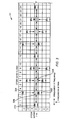
- FIG. 5 illustrates a plot of a channel gain over time in a system employing automatic gain control.
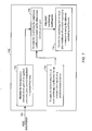
- FIG. 6 a method for determining adjusted combining coefficients accounting for automatic gain control timing in a wireless device.
- FIG. 7 illustrates an apparatus for determining adjusted combining coefficients accounting for automatic gain control timing in a wireless device.
- FIG. 8 illustrates an exemplary plot of a simulation showing improved performance characteristics of a system accounting for automatic gain control over a system that does not account for automatic gain control.
- the present disclosure discusses apparatus and methods for adjusting for the effects of automatic gain control when combining pilot interlaces in an interlace filter of a communication system, such as an OFDM system.
- the disclosed methods and apparatus achieve reversal of the effects of discontinuities introduced by automatic gain control (AGC) when combining pilot interlaces. Accordingly, channel estimation, and, thus, transceiver performance is improved
- FIG. 1 illustrates a block diagram of an exemplary OFDM transceiver or portion of a transceiver according to the present disclosure.
- the system of FIG. 1 may employ the disclosed techniques for making timing adjustments using pilot tones, which are used for channel estimation.
- the system 100 which may be a transceiver or one or more processors, hardware, firmware, or a combination thereof, receives a transmitted RF signal as shown.
- a front end processing block 102 receives the RF signal and performs various processing functions including analog-to-digital conversion; down conversion, and AGC (Automatic Gain Control) unit 103.
- the AGC unit 103 may further include low noise amplifier (LNA) control, a digital variable gain amplifier (DVGA), or a combination thereof.
- LNA low noise amplifier
- DVGA digital variable gain amplifier
- the resultant signals are sent to a sample server 104, which effects the actual timing window (e.g., the FFT timing window) for sampling the subcarriers within the signal.
- the output of the sample server 104 which is a synchronized digital signal, is then input to an optional frequency rotator , which operates in conjunction with and under control of a frequency tracking block to cause rotation or shifting of the phase of the signal in frequency in order to make fine adjustments or corrections in frequency.
- the signals from either sample server 104 or frequency rotator 106, if utilized, are sent to a fast Fourier Transform (FFT) 110, which performs a discrete Fourier transform of the signal. More particularly, the FFT 110 extracts the data carriers from the pilot carriers.
- the data is sent to a demodulator 112 for demodulation of the data, and a subsequent decoder 114 for decoding of the data according to any suitable encoding scheme utilized.
- the output of the decoder is a bit steam for use by other processors, software, or firmware within a transceiver device.
- the pilot tones extracted by FFT 110 are sent to a pilot buffer 116, which buffers a number of pilot interlaces from one or more OFDM symbols.
- the buffer 116 may be configured to buffer multiple interlaces for use in combining the interlaces.
- the buffered pilot interlaces are delivered by buffer 116 to a channel estimation block or unit 118, which estimates the channels using the interlaced pilot tones inserted by the transmitter (not shown) into the symbols of the digital signal.
- the channel estimation yields a channel impulse response (CIR) ⁇ k.n to be used in timing tracking and a channel frequency response ⁇ k,n to be used for demodulation of the channel data by demodulator 112.
- CIR channel impulse response
- the channel impulse response (CIR) ⁇ k,n is delivered to a timing tracking block 120, which effects a timing tracking algorithm or method to determine a timing decision for the FFT window that is used by sample server 104.
- the system 100 also includes a processor 121, such as a digital signal processor (DSP), in communication with the channel estimation unit 118 and may be utilized to implement various processing operations, such as those that will be discussed later in connection with the method of FIG. 6 .
- DSP digital signal processor
- a channel estimation unit or block (e.g., 118) is utilized to obtain a channel transfer function estimate ⁇ k,n of the channel at each carrier k and OFDM symbol time n for demodulation of the data symbols and an estimate ⁇ k,n of the corresponding channel impulse response (CIR) for use in time tracking.
- the pilot tones are transmitted according a predetermined interlace staggering scheme 200 as illustrated by FIG. 2 , which illustrates the scheme for the first few carriers k and symbol times n. As may be seen in FIG.
- pilot tones p are inserted at every 12 th carrier for a total of up to N K /12 pilots tones per OFDM symbol n (e.g., at symbol time 0 in FIG. 3 there can be a N K /12 number of pilot tones where carrier 0 is used for a pilot tone, but N K /12-1 for symbols having pilots staggered such as a OFDM symbol time 1, 2, and 3 in FIG. 2 ), where N K is the total number of carriers.
- the first pilot tone is inserted at carrier 3
- the first pilot tone is inserted at carrier 6, and so forth.
- mod4 i.e., 0 ⁇ m ⁇ 3
- the pattern repeats after four OFDM symbols (e.g., OFDM symbol times 0-3).
- pilot interlaces from seven (7) consecutive OFDM symbols, which are buffered in a pilot interlace buffer (not shown), in a paired fashion to find a channel estimate for a time n .
- each pair of pilot tones corresponds to the same pilot (i.e., l th pilot) at different OFDM symbol time instances and they are combined to estimate the channel corresponding to the time of data.
- FIG. 3 illustrates a diagram 300 of the exemplary interlacing of pilot symbols p shown in FIG. 2 with further visual representation of the combining of pilot tones.
- a first pilot p l.m for l 0, for example, is combined in time for each of the carriers (i.e., interpolated in time).
- a pair 302, 304 of pilots (p 0.1 ) at carrier 3 i.e., an offset of 3 carriers (3 ⁇ n mod4), thus part of same m+1 interlace) and times n + 1 and n - 3 , respectively, are combined to the time of symbol time n ( n being 0 in this example) as indicated with vertical arrows.
- an interpolated pilot tone 306 may then be interpolated in frequency with other interpolated pilot tones 308 or a pilot tone extant in the n time OFDM symbol 310, as illustrated by the horizontal arrows in FIG. 3 .
- Combining pilot tones may be effected using any known techniques including interpolation techniques. It is further noted that the interlaces may be combined in the frequency or time domain, as will be explained in detail below. From a theoretical point of view, both strategies of combining (frequency or time domain) yield exactly the same performance. It is noted, however, that combining in time may present less stress on a channel IFFT in a fixed point implementation (since its shorter).
- a first strategy for combing pilot tones of the interlaces is combining in the frequency domain, as mentioned above, using a filter.
- Combining the pilot tones in the frequency domain can be mathematically expressed as shown in equation (1) below providing the pilot tone estimate H k.n .
- N P is the length of the final time-domain channel estimate
- m l .[n-k] 4 are the filter coefficients of the filter
- N c and N nc are the causal and non-causal filter lengths, respectively.
- the notation [ ] 4 is an abbreviated notation where the subscript 4 is a reminder of the modulo operation xmod4.
- the filter coefficients m l .[n-k]4 are chosen to effect linear interpolation between two pilot-tones and are shown in Table 1 below.
- a more general filter could incorporate pilot tones from other interlaces (i.e., also work diagonally), with an according increase in complexity.
- taps below a certain threshold are set to zero, and after zero-padding with 2 N P zeros (to interpolate in frequency) an FFT is taken to arrive at the final channel estimate ⁇ k,n , where N P is the length of the final time-domain channel estimate.
- an IFFT of the pilot tones of each interlace is taken. More specifically, zero-padding of the N K 12 (or N K 12 + 1 for interlace 0) pilot tones P l.m to N IL is performed, where N K represents the number of carriers, and N IL represents the length of interlaces in frequency after zero padding (i.e., extending a signal (or spectrum) with zeros to extend the time (or frequency band) limits).
- N K represents the number of carriers
- N IL represents the length of interlaces in frequency after zero padding (i.e., extending a signal (or spectrum) with zeros to extend the time (or frequency band) limits).
- the number of carriers N K is 1705, 3409, or 6817 dependent on the mode of operation.
- ISDB-T systems as a further example typically have 108, 216, or 432 carriers N K dependent on the mode of operation.
- the length of the interlaces N IL are 256 or 512 or 1024, dependent on the mode of operation.
- ISDB-T systems as another example, would have interlaces lengths of 16 or 32 or 64 dependent on the mode of operation.
- b k.m are referred to as the interlace buffers. Because each interlace channel estimate is to be used four (4) times for the calculation of channel estimates at consecutive OFDM symbol times, the b k,m are buffered, requiring at least 7 N IL complex storage spaces for the presently disclosed example.
- the channel estimate h k.n may then be split into four segments as illustrated in FIG. 4 .
- the time-domain channel taps obtained here are simply the IFFT of the combined pilot tones of equation (1) above.
- Combining in the time domain may simply be viewed as one way of implementing a fast algorithm for the discrete Fourier transform (DFT) of the pilot tones combined in frequency.
- DFT discrete Fourier transform
- the equivalence is derived as follows for the case that we use exactly four consecutive interlaces and all four (4) filter coefficients m l.k are one (a more general case with filtering will be considered later). Then each time interlace h ⁇ k,m can be viewed as being obtained from a frequency-domain channel H k.n by down-sampling and advancing (in frequency).
- ⁇ kmu 1 4 ⁇ e + j ⁇ 2 ⁇ ⁇ N P ⁇ mk ⁇ e + j ⁇ 2 ⁇ ⁇ N P ⁇ muN IL .
- N IL N P 1 4
- the additional filtering introduced with the coefficients m l,k can be viewed to only operate on a given interlace, so that it is equivalent in time and frequency domain (i.e., linear operations are interchangeable). Whether the filtered interlaces are then combined in frequency or time domain is the same according to the presently disclosed methodologies.
- the combining coefficients ( m l.k in this presentation) for combining the pilot interlaces are constant, such as may be seen in the Table 1 above where the coefficients are linearly interpolated in time.
- the coefficients m l.k may be chosen according to different criteria/methodologies. For example, the coefficients could be chosen to minimize the minimum mean square error (MMSE) between the actual channel and the channel estimate.
- MMSE minimum mean square error
- An exemplary derivation for an MMSE interlace estimator is as follows.
- AWGN additive white Gaussian noise
- r HH l E ⁇ H k , n ⁇ H k , n + l C / N 0
- r HH ( l ) is the normalized auto-correlation of the fade process at time-offset l
- E denotes expected value
- C / N 0 is the carrier to noise-ratio
- Timing adjustments are necessitated due to phase shift between pilot tones at a current n OFDM symbol and previous interlaces.
- Known fine timing tracking algorithms for example, retard or advance the position of the FFT window at a sample server (to be discussed later). These timing adjustments correspond to phase shifts in the frequency-domain and thus affect channel estimation:
- the pilot tones at time n which have a phase shift compared with the previous interlaces and, thus, channel estimation should be configured to correct for this phase shift to combine the interlace buffers.
- the advance or retarding of the FFT window may be also referred to as an advance or retard of the sampling of the OFDM symbol.
- FIG. 4 illustrates a plot of the channel gain without automatic gain control (AGC). Without AGC, the plot of the channel gain smoothly changes.
- AGC automatic gain control
- the gain of the receiver is adjusted such that the samples within one symbol (or more precisely within the FFT window) have a roughly constant power.
- This gain adjustment which may include analog stages (like a Low Noise Amplifier, LNA) and/or digital stages (like a Digital Variable Gain Amplifier, DVGA) enables the receiver to operate with fewer bits in the blocks after the adjustment since the dynamic range of the signal is reduced
- LNA Low Noise Amplifier
- DVGA Digital Variable Gain Amplifier
- the smoothly changing channel of FIG. 4 is "chopped" up in pieces with discontinuities by the AGC. Furthermore, this effect of the AGC on channel estimation is more pronounced the more interlaces that are combined: It is recognized, however, that performance of the receiver when combining interlaces is improved if the discontinuities introduced by the AGC are "reversed” or negated. This may be most efficiently effected by changing the combining coefficients m l,k to reverse the effects of the AGC.
- AWGN complex additive white Gaussian noise
- an interlace combining filter in the channel estimation block operates on the AGC adjusted observations according to equation (17) below in order to normalize the AGC gain.
- P k , m ⁇ g n g m As may be seen in this equation, this normalization is effected by multiplying the pilot tone for a m th interlace by the ratio of an AGC gain g(n) for a symbol time n to an AGC gain g(m) for an interlace m .
- the ratio of g(n) to g(m) is termed a normalization gain, which serves to normalize the AGC gain to a predetermined time n .
- the value m may be bounded according to the condition ( n -3) ⁇ m ⁇ ( n +3) in the instance of a 7 interlace combining scheme for DVB or ISDB systems. This may be less for FLO systems or other systems having interlace combining schemes of less than 7 interlaces.
- the AGC adjustment may be performed in time or frequency domain with the exact same performance benefits.
- the adjustment may be thus incorporated into the interlace filter by defining an adjusted combining coefficient m l,k according to the following relationship (18).
- m ⁇ l , k m l , k ⁇ g n g ⁇ n - k - l ⁇ 4 .
- the combining coefficient m l,k is multiplied by the normalized AGC gain, which may be derived from equation (17). It is noted that for equation (18) a system using 4 interlaces is assumed, such as the system that was illustrated in FIG. 2 .
- the value of m may be represented by ( n -( k - l ⁇ 4)) in a four interlace scheme.
- equation (18) may be modified to account for other systems, such as the 2 interlace system used in FLO systems. This adjusted coefficient may then be substituted in equation (1) above, for example, to determine a channel estimate H k,n .
- the integer portion of ( l ( n )- l ( n -( k - l ⁇ 4)))/2 b in equation (19) corresponds to a simple shift.
- the power of 2 of the non-integer portion can be approximated with a polynomial of degree 2.
- DSP digital signal processor
- FIG. 6 illustrates a flow diagram of a method for determining combining coefficients in a multi carrier OFDM system where the coefficients are normalized to account for the effects of the AGC.
- the method 600 begins at a start block 602.
- Flow then proceeds to block 604 where a normalization gain of an applied automatic gain control is determined.
- the normalization gain is normalized to a predefined time, such as a symbol time n .
- the procedure of block 604 effects finding the ratio g(n) / g(m) discussed above in connection with equations (17), (18), and (19).
- flow proceeds to block 606 where two or more combining coefficients for an interlace filter are determined.
- the coefficients may be determined to any one of a number of known predetermined criteria, such as through linear interpolation or MMSE as discussed above. It is noted that block 606, although shown sequentially after block 604, the operation of block 606 may alternatively occur prior to the operation of block 604 or concurrent with the operation of block 604. It is further noted that a processor 121, such as a digital signal processor (DSP), the channel estimation block 118, a combination thereof, or any other suitable means may effect the operations of blocks 604 and 606, for example.
- DSP digital signal processor
- block 608 the combining coefficients (e.g., m l,k ) are modified based on the determined normalization gain. This operation was described previously in connection with equations (18) and (19), where a modified or adjusted coefficient m l,k is calculated. It is noted that a digital signal processor (DSP), such as DSP 121, the channel estimation block 118, a combination thereof, or any other suitable means, may effect the functionality of block 608.
- DSP digital signal processor
- the process 600 ends at block 610.
- the combining coefficients are then used by the interlace filter (e.g., 118) to determine a channel estimate, as discussed above and also in the related application entitled "TIMING ADJUSTMENTS FOR CHANNEL ESTIMATION IN A MULTI CARRIER SYSTEM" having a Attorney Docket No. 061615U1, filed concurrently herewith. It is noted that the process 600 is continually repeated during reception and processing of signals (e.g., channel estimation) in a transceiver.
- FIG. 7 illustrates an apparatus 700 for determining combining coefficients for channel estimation in a wireless device.
- the apparatus 700 receives automatic gain control (AGC) gain information at an input 702, which delivers the signal to a module 704 for determining a normalization gain of an applied automatic gain control normalized to a predefined time.
- AGC automatic gain control
- input 702 may receive the AGC gain information from the AGC, such as AGC 103 via a communication link 122 as illustrated in FIG. 1 .
- module 704 may be implemented by channel estimation and interlace filter 118, DSP 121, a combination thereof or any other suitable processing means
- Apparatus 700 also includes a module 706 for determining two or more combining coefficients for an interlace filter based on a predetermined criterion.
- Module 706 may be implemented by channel estimation block 118 in FIG. 1 , a DSP (121), a combination thereof, as examples, or any other suitable processing means.
- the determined normalization gain is output by means 704 and two or more combining coefficients are output by module 706. Both of these outputs are input to module 708 for modifying the combining coefficients based on the determined normalization gain. As discussed previously, module 708 may modify or adjust the coefficients by multiplying the normalization gain with the combining coefficient to achieve the adjusted combining coefficients. It is noted that module 708 may be used to effect one of equations (17)-(19) above. Further, module 708 may be implemented, for example, by channel estimation block 118, DSP 121, or any combination thereof.
- the adjusted combining coefficients are output by module 708 for use by other processing in a transceiver to determine a channel estimate of a received OFDM signal.
- FIG. 7 illustrates a module 710 within apparatus 700 for combining two or more pilot interlaces of symbols received in a transceiver using the adjusted combining coefficients.
- Module 710 may be implemented by the channel estimation unit and interlace filter 118 as shown in FIG. 1 , as an example. It is also noted here that apparatus 700 may be implemented within a transceiver, such as an OFDM transceiver, and may consist of hardware, software, firmware, or any combination thereof.
- FIG. 8 gives a graphic example of simulation results evincing a performance improvement achieved using the AGC adjustments discussed herein.
- This figure illustrates the carrier-to-noise ratio (C/N), which is specified in dB, required to achieve a bit error rate after Viterbi decoding (VBER) of 2 ⁇ 10 -4 in a typical urban channel with 6 paths (TU6) and varying maximum Doppler frequency, as an example.
- VBER Viterbi decoding
- a transceiver becomes operable at a maximum Doppler of approximately 100Hz when using AGC adjustments (see e.g., the plot demarcated with squares), whereas without AGC adjustments the transceiver is limited to 70Hz (see e.g., the plot demarcated with diamonds).
- the disclosed apparatus and methods effect improved channel estimation performance of receiver portion of a transceiver. This is accomplished in particular, by reversing the discontinuities introduced by AGC through determination of a normalization gain, which is normalized to particular symbol time. This normalization gain, in turn, is used to adjust combining coefficients used in an interlace filter for determining channel estimation.
- DSP digital signal processor
- ASIC application specific integrated circuit
- FPGA field programmable gate array
- a general purpose processor may be a microprocessor, but in the alternative, the processor may be any conventional processor, controller, microcontroller, or state machine.
- a processor may also be implemented as a combination of computing devices, e.g., a combination of a DSP and a microprocessor, a plurality of microprocessors, one or more microprocessors in conjunction with a DSP core, or any other such configuration.
- a software module may reside in RAM memory, flash memory, ROM memory, EPROM memory, EEPROM memory, registers, hard disk, a removable disk, a CD-ROM, or any other form of storage medium known in the art.
- An exemplary storage medium e.g., memory 124 in FIG. 1
- the processor can read information from, and write information to, the storage medium.
- the storage medium may be integral to the processor.
- the processor and the storage medium may reside in an ASIC.
- the ASIC may reside in a user terminal.
- the processor and the storage medium may reside as discrete components in a user terminal.
Landscapes
- Engineering & Computer Science (AREA)
- Signal Processing (AREA)
- Computer Networks & Wireless Communication (AREA)
- Power Engineering (AREA)
- Circuits Of Receivers In General (AREA)
- Synchronisation In Digital Transmission Systems (AREA)
- Mobile Radio Communication Systems (AREA)
- Control Of Amplification And Gain Control (AREA)
- Detection And Prevention Of Errors In Transmission (AREA)
- Cash Registers Or Receiving Machines (AREA)
- Control Of Metal Rolling (AREA)
- Cable Transmission Systems, Equalization Of Radio And Reduction Of Echo (AREA)
Claims (15)
- Ein Verfahren zum Anpassen bzw. Einstellen hinsichtlich der Auswirkungen von Effekten einer automatischen Verstärkungssteuerung beim Kombinieren von Pilot-Interlaces unter Verwendung eines Interlace-Kombinationsfilters eines Kommunikationssystems, wobei das Verfahren Folgendes aufweist:Bestimmen (604) einer Normalisierungsverstärkung einer angewandten automatischen Verstärkungssteuerung, die auf eine vordefinierte Zeit normalisiert ist;Bestimmen (606) von zwei oder mehr Koeffizienten des Interlace-Kombinationsfilters basierend auf einem vorbestimmten Kriterium; undModifizieren (608) jedes der beiden oder mehr Koeffizienten basierend auf der bestimmten Normalisierungsverstärkung, um angepasste Koeffizienten zu erhalten.
- Verfahren nach Anspruch 1, wobei das Modifizieren (608) der Koeffizienten das Berechnen des Produkts der Normalisierungsverstärkung und mindestens eines der zwei oder mehr Koeffizienten aufweist.
- Verfahren nach Anspruch 1, wobei das vorbestimmte Kriterium eine lineare Interpolation und/oder eine Minimierung des minimalen mittleren quadratischen Fehlers aufweist.
- Verfahren nach Anspruch 1, das weiter Folgendes aufweist:Kombinieren von zwei oder mehr Pilot-Interlaces von Symbolen, die in einem Transceiver empfangen werden, unter Verwendung der angepassten Koeffizienten des Interlace-Kombinationsfilters.
- Verfahren nach Anspruch 4, das weiter Folgendes aufweist:Erlangen einer Kanalschätzung basierend auf den kombinierten Pilot-Interlaces.
- Verfahren nach Anspruch 5, das weiter Folgendes aufweist:Demodulieren von Daten, die in einem Symbol enthalten sind, unter Verwendung der Kanalschätzung.
- Verfahren nach Anspruch 4, wobei die Symbole orthogonale frequenzgemultiplexte Symbole sind.
- Verfahren nach Anspruch 4, wobei das Kombinieren der zwei oder mehr Pilot-Interlaces in entweder der Frequenz-Domain oder der Zeit-Domain durchgeführt wird.
- Eine Vorrichtung zum Anpassen hinsichtlich der Auswirkungen von Effekten einer automatischen Verstärkungssteuerung beim Kombinieren von Pilot-Interlaces unter Verwendung eines Interlace-Kombinationsfilters eines Kommunikationssystems, die Folgendes aufweist:Mittel (704) zum Bestimmen einer Normalisierungsverstärkung einer angewandten automatischen Verstärkungssteuerung, die auf eine vordefinierte Zeit normalisiert ist;Mittel (706) zum Bestimmen von zwei oder mehr Koeffizienten des Interlace-Kombinationsfilters basierend auf einem vorbestimmten Kriterium; undMittel (708) zum Modifizieren jedes der zwei oder mehr Kombinationskoeffizienten basierend auf der bestimmten Normalisierungsverstärkung, um die angepassten Koeffizienten zu erhalten.
- Vorrichtung nach Anspruch 9, wobei die Mittel (708) zum Modifizieren der Koeffizienten weiter Mittel zum Berechnen des Produkts der Normalisierungsverstärkung und mindestens eines der zwei oder mehr Koeffizienten beinhaltet.
- Vorrichtung nach Anspruch 9, wobei das vorbestimmte Kriterium, das von dem Mittel zum Bestimmen von zwei oder mehr Koeffizienten für einen Interlace-Kombinationsfilter verwendet wird, eine lineare Interpolation und/oder eine Minimierung des minimalen mittleren quadratischen Fehlers beinhaltet.
- Vorrichtung nach Anspruch 9, die weiter Folgendes aufweist:Mittel zum Kombinieren von zwei oder mehr Pilot-Interlaces von Symbolen,die in einem Transceiver empfangen wurden, unter Verwendung der angepassten Koeffizienten des Interlace-Kombinationsfilters.
- Vorrichtung nach Anspruch 12, die weiter Folgendes aufweist:Mittel zum Erlangen einer Kanalschätzung basierend auf kombinierten Pilot-Interlaces.
- Vorrichtung nach Anspruch 12, wobei die Vorrichtung angepasst ist, um unter Verwendung der korrigierten Kanalschätzung Daten zu demodulieren, die in den Symbolen enthalten sind.
- Ein Computerprogrammprodukt zum Anpassen hinsichtlich der Auswirkungen von Effekten einer automatischen Verstärkungssteuerung beim Kombinieren von Pilot-Interlaces unter Verwendung eines Interlace-Kombinationsfilters eines Kommunikationssystems, das Folgendes aufweist:ein computerlesbares Medium, das Folgendes aufweist:Code um zu bewirken, dass ein Computer eine Normalisierungsverstärkung einer angewandten automatischen Verstärkungssteuerung bestimmt, die auf eine vordefinierte Zeit normalisiert ist;Code um zu bewirken, dass der Computer zwei oder mehr Koeffizienten des Interlace-Kombinationsfilters basierend auf einem vorbestimmten Kriterium bestimmt; undCode um zu bewirken, dass der Computer jeden der zwei oder mehr Koeffizienten basierend auf der bestimmten Normalisierungsverstärkung modifiziert, um angepasste Koeffizienten zu erhalten.
Applications Claiming Priority (4)
| Application Number | Priority Date | Filing Date | Title |
|---|---|---|---|
| US89306007P | 2007-03-05 | 2007-03-05 | |
| US89305807P | 2007-03-05 | 2007-03-05 | |
| US11/777,263 US20080219332A1 (en) | 2007-03-05 | 2007-07-12 | Apparatus and methods accounting for automatic gain control in a multi carrier system |
| PCT/US2008/055807 WO2008109607A1 (en) | 2007-03-05 | 2008-03-04 | Apparatus and methods accounting for effects of discontinuities at the output of automatic gain control in a multi carrier system |
Publications (2)
| Publication Number | Publication Date |
|---|---|
| EP2130338A1 EP2130338A1 (de) | 2009-12-09 |
| EP2130338B1 true EP2130338B1 (de) | 2011-12-28 |
Family
ID=41161266
Family Applications (2)
| Application Number | Title | Priority Date | Filing Date |
|---|---|---|---|
| EP08731357A Not-in-force EP2130338B1 (de) | 2007-03-05 | 2008-03-04 | Vorrichtung und Verfahren für Diskontinuitätseffekte am Ausgang einer automatischen Verstärkungsregelung in einem Multicarrier-System |
| EP08743672A Withdrawn EP2130339A1 (de) | 2007-03-05 | 2008-03-04 | Timing-anpassungen für kanalschätzungen in einem mehrträgersystem |
Family Applications After (1)
| Application Number | Title | Priority Date | Filing Date |
|---|---|---|---|
| EP08743672A Withdrawn EP2130339A1 (de) | 2007-03-05 | 2008-03-04 | Timing-anpassungen für kanalschätzungen in einem mehrträgersystem |
Country Status (11)
| Country | Link |
|---|---|
| EP (2) | EP2130338B1 (de) |
| JP (2) | JP5242599B2 (de) |
| KR (2) | KR101129207B1 (de) |
| CN (1) | CN101641920B (de) |
| AT (1) | ATE539530T1 (de) |
| BR (2) | BRPI0808485A2 (de) |
| CA (2) | CA2678113A1 (de) |
| ES (1) | ES2376016T3 (de) |
| RU (2) | RU2009136569A (de) |
| TW (2) | TWI370650B (de) |
| WO (2) | WO2008109607A1 (de) |
Families Citing this family (8)
| Publication number | Priority date | Publication date | Assignee | Title |
|---|---|---|---|---|
| US20100182899A1 (en) * | 2009-01-17 | 2010-07-22 | Qualcomm Incorporated | OFDM Time Basis Matching With Pre-FFT Cyclic Shift |
| CN101662446B (zh) * | 2009-09-28 | 2013-01-16 | 中兴通讯股份有限公司 | 信道估计方法及装置 |
| JP5487996B2 (ja) * | 2010-01-25 | 2014-05-14 | 富士通株式会社 | 適応等化器および適応等化方法 |
| US8718210B2 (en) | 2011-09-20 | 2014-05-06 | Qualcomm Incorporated | Channel impulse response estimation for wireless receiver |
| US20130107785A1 (en) * | 2011-11-02 | 2013-05-02 | Qualcomm Incorporated | Tracking loop enhancements for mitigating signal interference and adjusting signal power |
| CN103368874B (zh) * | 2012-03-30 | 2016-07-06 | 富士通株式会社 | 信道估计装置、方法及用户设备 |
| CN103379607B (zh) * | 2012-04-17 | 2018-01-30 | 中兴通讯股份有限公司 | Td‑hspa+终端设备的增益控制方法和装置 |
| GB2497149B (en) * | 2012-05-22 | 2013-11-20 | Aeroflex Ltd | A noise power estimation method |
Family Cites Families (8)
| Publication number | Priority date | Publication date | Assignee | Title |
|---|---|---|---|---|
| US4630305A (en) * | 1985-07-01 | 1986-12-16 | Motorola, Inc. | Automatic gain selector for a noise suppression system |
| ATE301361T1 (de) * | 2001-11-30 | 2005-08-15 | Freescale Semiconductor Inc | Transientenkompensation für leistungverstärker in ofdm-systemen |
| US8428001B2 (en) * | 2005-03-10 | 2013-04-23 | Qualcomm Incorporated | Timing corrections in a multi carrier system and propagation to a channel estimation time filter |
| US8144824B2 (en) * | 2005-03-10 | 2012-03-27 | Qualcomm Incorporated | Trend influenced time tracking |
| JP4610401B2 (ja) * | 2005-04-13 | 2011-01-12 | 株式会社エヌ・ティ・ティ・ドコモ | チャネル推定装置 |
| CN100518151C (zh) * | 2005-05-01 | 2009-07-22 | 中兴通讯股份有限公司 | 多输入多输出的信道估计装置、系统及方法 |
| JP2006352746A (ja) * | 2005-06-20 | 2006-12-28 | Fujitsu Ltd | 直交周波数分割多重伝送用受信機 |
| EP2031783A1 (de) * | 2006-08-03 | 2009-03-04 | Panasonic Corporation | Empfangsgerät, empfangsverfahren und integrierte schaltung |
-
2008
- 2008-03-04 EP EP08731357A patent/EP2130338B1/de not_active Not-in-force
- 2008-03-04 CA CA002678113A patent/CA2678113A1/en not_active Abandoned
- 2008-03-04 KR KR1020097020684A patent/KR101129207B1/ko not_active Expired - Fee Related
- 2008-03-04 RU RU2009136569/09A patent/RU2009136569A/ru not_active Application Discontinuation
- 2008-03-04 BR BRPI0808485-8A patent/BRPI0808485A2/pt not_active IP Right Cessation
- 2008-03-04 WO PCT/US2008/055807 patent/WO2008109607A1/en not_active Ceased
- 2008-03-04 WO PCT/US2008/055797 patent/WO2008109600A1/en not_active Ceased
- 2008-03-04 EP EP08743672A patent/EP2130339A1/de not_active Withdrawn
- 2008-03-04 CN CN2008800070878A patent/CN101641920B/zh not_active Expired - Fee Related
- 2008-03-04 CA CA002677971A patent/CA2677971A1/en not_active Abandoned
- 2008-03-04 KR KR1020097020683A patent/KR101126989B1/ko not_active Expired - Fee Related
- 2008-03-04 ES ES08731357T patent/ES2376016T3/es active Active
- 2008-03-04 RU RU2009136568/09A patent/RU2009136568A/ru not_active Application Discontinuation
- 2008-03-04 BR BRPI0808484-0A patent/BRPI0808484A2/pt not_active IP Right Cessation
- 2008-03-04 AT AT08731357T patent/ATE539530T1/de active
- 2008-03-04 JP JP2009552836A patent/JP5242599B2/ja not_active Expired - Fee Related
- 2008-03-04 JP JP2009552837A patent/JP5204131B2/ja not_active Expired - Fee Related
- 2008-03-05 TW TW097107709A patent/TWI370650B/zh not_active IP Right Cessation
- 2008-03-05 TW TW097107712A patent/TWI379559B/zh not_active IP Right Cessation
Also Published As
| Publication number | Publication date |
|---|---|
| JP5242599B2 (ja) | 2013-07-24 |
| KR20090115772A (ko) | 2009-11-05 |
| WO2008109607A1 (en) | 2008-09-12 |
| JP2010520723A (ja) | 2010-06-10 |
| TW200849903A (en) | 2008-12-16 |
| KR20090115771A (ko) | 2009-11-05 |
| KR101129207B1 (ko) | 2012-04-12 |
| CN101641920A (zh) | 2010-02-03 |
| CN101641920B (zh) | 2013-05-22 |
| BRPI0808485A2 (pt) | 2014-07-01 |
| RU2009136568A (ru) | 2011-04-10 |
| CA2677971A1 (en) | 2008-09-12 |
| RU2009136569A (ru) | 2011-04-10 |
| ATE539530T1 (de) | 2012-01-15 |
| TWI370650B (en) | 2012-08-11 |
| TW200913583A (en) | 2009-03-16 |
| EP2130339A1 (de) | 2009-12-09 |
| JP2010520722A (ja) | 2010-06-10 |
| EP2130338A1 (de) | 2009-12-09 |
| WO2008109600A1 (en) | 2008-09-12 |
| ES2376016T3 (es) | 2012-03-08 |
| BRPI0808484A2 (pt) | 2014-07-08 |
| TWI379559B (en) | 2012-12-11 |
| JP5204131B2 (ja) | 2013-06-05 |
| KR101126989B1 (ko) | 2012-04-12 |
| CA2678113A1 (en) | 2008-09-12 |
Similar Documents
| Publication | Publication Date | Title |
|---|---|---|
| US20080219332A1 (en) | Apparatus and methods accounting for automatic gain control in a multi carrier system | |
| US8098567B2 (en) | Timing adjustments for channel estimation in a multi carrier system | |
| EP2130338B1 (de) | Vorrichtung und Verfahren für Diskontinuitätseffekte am Ausgang einer automatischen Verstärkungsregelung in einem Multicarrier-System | |
| KR100934146B1 (ko) | Ofdm 심볼 시간 추적 정보를 사용하는 fft 수집 윈도 포지셔닝 | |
| US8275055B2 (en) | Receiver for differentially modulated multicarrier signals | |
| US20040184399A1 (en) | Channel estimation in OFDM systems | |
| EP0953247A1 (de) | Verfahren und einrichtung zur kanlschätzung für ofdm-übertragungssystem | |
| US7929627B2 (en) | OFDM receiver, integrated circuit and receiving method | |
| KR100869432B1 (ko) | Ofdm 수신기 | |
| JP2004032748A (ja) | 直交周波数分割多重化通信システムのためのマルチパス等化技術 | |
| EP2002622A1 (de) | Kanalschätzung für kanäle mit schnellem dispersivem fading | |
| WO2007143588A2 (en) | Channel estimation | |
| WO2009125599A1 (ja) | 受信装置、受信方法、集積回路、デジタルテレビ受像機、プログラム | |
| EP2077649A1 (de) | Kanalschätzungsverfahren und Kanalschätzer dafür | |
| US8155223B2 (en) | Receiving device, receiving method, and program | |
| US8428538B2 (en) | Channel estimator | |
| JP2002344414A (ja) | Ofdm復調装置及び方法 | |
| Cho et al. | A Performance Comparison of Channel Estimation Methods for ISDB-T Systems | |
| US20080165673A1 (en) | System and method for demodulating data in an orthogonal frequency division modulation system |
Legal Events
| Date | Code | Title | Description |
|---|---|---|---|
| PUAI | Public reference made under article 153(3) epc to a published international application that has entered the european phase |
Free format text: ORIGINAL CODE: 0009012 |
|
| 17P | Request for examination filed |
Effective date: 20090915 |
|
| AK | Designated contracting states |
Kind code of ref document: A1 Designated state(s): AT BE BG CH CY CZ DE DK EE ES FI FR GB GR HR HU IE IS IT LI LT LU LV MC MT NL NO PL PT RO SE SI SK TR |
|
| DAX | Request for extension of the european patent (deleted) | ||
| 17Q | First examination report despatched |
Effective date: 20100621 |
|
| GRAP | Despatch of communication of intention to grant a patent |
Free format text: ORIGINAL CODE: EPIDOSNIGR1 |
|
| RTI1 | Title (correction) |
Free format text: APPARATUS AND METHOD ACCOUNTING FOR EFFECTS OF DISCONTINUITIES AT THE OUTPUT OF AUTOMATIC GAIN CONTROL IN A MULTI CARRIER SYSTEM |
|
| RTI1 | Title (correction) |
Free format text: APPARATUS AND METHOD ACCOUNTING FOR EFFECTS OF DISCONTINUITIES AT THE OUTPUT OF AUTOMATIC GAIN CONTROL IN A MULTI CARRIER SYSTEM |
|
| GRAS | Grant fee paid |
Free format text: ORIGINAL CODE: EPIDOSNIGR3 |
|
| GRAA | (expected) grant |
Free format text: ORIGINAL CODE: 0009210 |
|
| AK | Designated contracting states |
Kind code of ref document: B1 Designated state(s): AT BE BG CH CY CZ DE DK EE ES FI FR GB GR HR HU IE IS IT LI LT LU LV MC MT NL NO PL PT RO SE SI SK TR |
|
| REG | Reference to a national code |
Ref country code: GB Ref legal event code: FG4D |
|
| REG | Reference to a national code |
Ref country code: CH Ref legal event code: EP |
|
| REG | Reference to a national code |
Ref country code: AT Ref legal event code: REF Ref document number: 539530 Country of ref document: AT Kind code of ref document: T Effective date: 20120115 |
|
| REG | Reference to a national code |
Ref country code: IE Ref legal event code: FG4D |
|
| REG | Reference to a national code |
Ref country code: DE Ref legal event code: R096 Ref document number: 602008012342 Country of ref document: DE Effective date: 20120308 Ref country code: ES Ref legal event code: FG2A Ref document number: 2376016 Country of ref document: ES Kind code of ref document: T3 Effective date: 20120308 |
|
| REG | Reference to a national code |
Ref country code: NL Ref legal event code: VDEP Effective date: 20111228 |
|
| PG25 | Lapsed in a contracting state [announced via postgrant information from national office to epo] |
Ref country code: NO Free format text: LAPSE BECAUSE OF FAILURE TO SUBMIT A TRANSLATION OF THE DESCRIPTION OR TO PAY THE FEE WITHIN THE PRESCRIBED TIME-LIMIT Effective date: 20120328 Ref country code: LT Free format text: LAPSE BECAUSE OF FAILURE TO SUBMIT A TRANSLATION OF THE DESCRIPTION OR TO PAY THE FEE WITHIN THE PRESCRIBED TIME-LIMIT Effective date: 20111228 |
|
| LTIE | Lt: invalidation of european patent or patent extension |
Effective date: 20111228 |
|
| PG25 | Lapsed in a contracting state [announced via postgrant information from national office to epo] |
Ref country code: SE Free format text: LAPSE BECAUSE OF FAILURE TO SUBMIT A TRANSLATION OF THE DESCRIPTION OR TO PAY THE FEE WITHIN THE PRESCRIBED TIME-LIMIT Effective date: 20111228 Ref country code: HR Free format text: LAPSE BECAUSE OF FAILURE TO SUBMIT A TRANSLATION OF THE DESCRIPTION OR TO PAY THE FEE WITHIN THE PRESCRIBED TIME-LIMIT Effective date: 20111228 Ref country code: GR Free format text: LAPSE BECAUSE OF FAILURE TO SUBMIT A TRANSLATION OF THE DESCRIPTION OR TO PAY THE FEE WITHIN THE PRESCRIBED TIME-LIMIT Effective date: 20120329 Ref country code: SI Free format text: LAPSE BECAUSE OF FAILURE TO SUBMIT A TRANSLATION OF THE DESCRIPTION OR TO PAY THE FEE WITHIN THE PRESCRIBED TIME-LIMIT Effective date: 20111228 Ref country code: LV Free format text: LAPSE BECAUSE OF FAILURE TO SUBMIT A TRANSLATION OF THE DESCRIPTION OR TO PAY THE FEE WITHIN THE PRESCRIBED TIME-LIMIT Effective date: 20111228 |
|
| PG25 | Lapsed in a contracting state [announced via postgrant information from national office to epo] |
Ref country code: BE Free format text: LAPSE BECAUSE OF FAILURE TO SUBMIT A TRANSLATION OF THE DESCRIPTION OR TO PAY THE FEE WITHIN THE PRESCRIBED TIME-LIMIT Effective date: 20111228 Ref country code: CY Free format text: LAPSE BECAUSE OF FAILURE TO SUBMIT A TRANSLATION OF THE DESCRIPTION OR TO PAY THE FEE WITHIN THE PRESCRIBED TIME-LIMIT Effective date: 20111228 |
|
| PG25 | Lapsed in a contracting state [announced via postgrant information from national office to epo] |
Ref country code: NL Free format text: LAPSE BECAUSE OF FAILURE TO SUBMIT A TRANSLATION OF THE DESCRIPTION OR TO PAY THE FEE WITHIN THE PRESCRIBED TIME-LIMIT Effective date: 20111228 Ref country code: CZ Free format text: LAPSE BECAUSE OF FAILURE TO SUBMIT A TRANSLATION OF THE DESCRIPTION OR TO PAY THE FEE WITHIN THE PRESCRIBED TIME-LIMIT Effective date: 20111228 Ref country code: SK Free format text: LAPSE BECAUSE OF FAILURE TO SUBMIT A TRANSLATION OF THE DESCRIPTION OR TO PAY THE FEE WITHIN THE PRESCRIBED TIME-LIMIT Effective date: 20111228 Ref country code: BG Free format text: LAPSE BECAUSE OF FAILURE TO SUBMIT A TRANSLATION OF THE DESCRIPTION OR TO PAY THE FEE WITHIN THE PRESCRIBED TIME-LIMIT Effective date: 20120328 Ref country code: EE Free format text: LAPSE BECAUSE OF FAILURE TO SUBMIT A TRANSLATION OF THE DESCRIPTION OR TO PAY THE FEE WITHIN THE PRESCRIBED TIME-LIMIT Effective date: 20111228 Ref country code: IS Free format text: LAPSE BECAUSE OF FAILURE TO SUBMIT A TRANSLATION OF THE DESCRIPTION OR TO PAY THE FEE WITHIN THE PRESCRIBED TIME-LIMIT Effective date: 20120428 |
|
| PG25 | Lapsed in a contracting state [announced via postgrant information from national office to epo] |
Ref country code: PT Free format text: LAPSE BECAUSE OF FAILURE TO SUBMIT A TRANSLATION OF THE DESCRIPTION OR TO PAY THE FEE WITHIN THE PRESCRIBED TIME-LIMIT Effective date: 20120430 Ref country code: PL Free format text: LAPSE BECAUSE OF FAILURE TO SUBMIT A TRANSLATION OF THE DESCRIPTION OR TO PAY THE FEE WITHIN THE PRESCRIBED TIME-LIMIT Effective date: 20111228 Ref country code: RO Free format text: LAPSE BECAUSE OF FAILURE TO SUBMIT A TRANSLATION OF THE DESCRIPTION OR TO PAY THE FEE WITHIN THE PRESCRIBED TIME-LIMIT Effective date: 20111228 |
|
| REG | Reference to a national code |
Ref country code: AT Ref legal event code: MK05 Ref document number: 539530 Country of ref document: AT Kind code of ref document: T Effective date: 20111228 |
|
| PG25 | Lapsed in a contracting state [announced via postgrant information from national office to epo] |
Ref country code: MC Free format text: LAPSE BECAUSE OF NON-PAYMENT OF DUE FEES Effective date: 20120331 Ref country code: DK Free format text: LAPSE BECAUSE OF FAILURE TO SUBMIT A TRANSLATION OF THE DESCRIPTION OR TO PAY THE FEE WITHIN THE PRESCRIBED TIME-LIMIT Effective date: 20111228 |
|
| REG | Reference to a national code |
Ref country code: CH Ref legal event code: PL |
|
| PLBE | No opposition filed within time limit |
Free format text: ORIGINAL CODE: 0009261 |
|
| STAA | Information on the status of an ep patent application or granted ep patent |
Free format text: STATUS: NO OPPOSITION FILED WITHIN TIME LIMIT |
|
| 26N | No opposition filed |
Effective date: 20121001 |
|
| REG | Reference to a national code |
Ref country code: IE Ref legal event code: MM4A |
|
| REG | Reference to a national code |
Ref country code: DE Ref legal event code: R097 Ref document number: 602008012342 Country of ref document: DE Effective date: 20121001 |
|
| PG25 | Lapsed in a contracting state [announced via postgrant information from national office to epo] |
Ref country code: CH Free format text: LAPSE BECAUSE OF NON-PAYMENT OF DUE FEES Effective date: 20120331 Ref country code: AT Free format text: LAPSE BECAUSE OF FAILURE TO SUBMIT A TRANSLATION OF THE DESCRIPTION OR TO PAY THE FEE WITHIN THE PRESCRIBED TIME-LIMIT Effective date: 20111228 Ref country code: LI Free format text: LAPSE BECAUSE OF NON-PAYMENT OF DUE FEES Effective date: 20120331 Ref country code: IE Free format text: LAPSE BECAUSE OF NON-PAYMENT OF DUE FEES Effective date: 20120304 |
|
| PG25 | Lapsed in a contracting state [announced via postgrant information from national office to epo] |
Ref country code: FI Free format text: LAPSE BECAUSE OF FAILURE TO SUBMIT A TRANSLATION OF THE DESCRIPTION OR TO PAY THE FEE WITHIN THE PRESCRIBED TIME-LIMIT Effective date: 20111228 |
|
| PG25 | Lapsed in a contracting state [announced via postgrant information from national office to epo] |
Ref country code: MT Free format text: LAPSE BECAUSE OF FAILURE TO SUBMIT A TRANSLATION OF THE DESCRIPTION OR TO PAY THE FEE WITHIN THE PRESCRIBED TIME-LIMIT Effective date: 20111228 |
|
| PG25 | Lapsed in a contracting state [announced via postgrant information from national office to epo] |
Ref country code: TR Free format text: LAPSE BECAUSE OF FAILURE TO SUBMIT A TRANSLATION OF THE DESCRIPTION OR TO PAY THE FEE WITHIN THE PRESCRIBED TIME-LIMIT Effective date: 20111228 |
|
| PGFP | Annual fee paid to national office [announced via postgrant information from national office to epo] |
Ref country code: DE Payment date: 20140331 Year of fee payment: 7 |
|
| PG25 | Lapsed in a contracting state [announced via postgrant information from national office to epo] |
Ref country code: LU Free format text: LAPSE BECAUSE OF NON-PAYMENT OF DUE FEES Effective date: 20120304 |
|
| PGFP | Annual fee paid to national office [announced via postgrant information from national office to epo] |
Ref country code: IT Payment date: 20140319 Year of fee payment: 7 Ref country code: ES Payment date: 20140325 Year of fee payment: 7 |
|
| PG25 | Lapsed in a contracting state [announced via postgrant information from national office to epo] |
Ref country code: HU Free format text: LAPSE BECAUSE OF FAILURE TO SUBMIT A TRANSLATION OF THE DESCRIPTION OR TO PAY THE FEE WITHIN THE PRESCRIBED TIME-LIMIT Effective date: 20080304 |
|
| REG | Reference to a national code |
Ref country code: FR Ref legal event code: PLFP Year of fee payment: 8 |
|
| PGFP | Annual fee paid to national office [announced via postgrant information from national office to epo] |
Ref country code: FR Payment date: 20150224 Year of fee payment: 8 Ref country code: GB Payment date: 20150224 Year of fee payment: 8 |
|
| REG | Reference to a national code |
Ref country code: DE Ref legal event code: R119 Ref document number: 602008012342 Country of ref document: DE |
|
| PG25 | Lapsed in a contracting state [announced via postgrant information from national office to epo] |
Ref country code: IT Free format text: LAPSE BECAUSE OF NON-PAYMENT OF DUE FEES Effective date: 20150304 |
|
| PG25 | Lapsed in a contracting state [announced via postgrant information from national office to epo] |
Ref country code: DE Free format text: LAPSE BECAUSE OF NON-PAYMENT OF DUE FEES Effective date: 20151001 |
|
| REG | Reference to a national code |
Ref country code: ES Ref legal event code: FD2A Effective date: 20160427 |
|
| PG25 | Lapsed in a contracting state [announced via postgrant information from national office to epo] |
Ref country code: ES Free format text: LAPSE BECAUSE OF NON-PAYMENT OF DUE FEES Effective date: 20150305 |
|
| GBPC | Gb: european patent ceased through non-payment of renewal fee |
Effective date: 20160304 |
|
| REG | Reference to a national code |
Ref country code: FR Ref legal event code: ST Effective date: 20161130 |
|
| PG25 | Lapsed in a contracting state [announced via postgrant information from national office to epo] |
Ref country code: FR Free format text: LAPSE BECAUSE OF NON-PAYMENT OF DUE FEES Effective date: 20160331 Ref country code: GB Free format text: LAPSE BECAUSE OF NON-PAYMENT OF DUE FEES Effective date: 20160304 |