EP2130416B1 - Leiterplattenschutz für eine batterie - Google Patents
Leiterplattenschutz für eine batterie Download PDFInfo
- Publication number
- EP2130416B1 EP2130416B1 EP08715998A EP08715998A EP2130416B1 EP 2130416 B1 EP2130416 B1 EP 2130416B1 EP 08715998 A EP08715998 A EP 08715998A EP 08715998 A EP08715998 A EP 08715998A EP 2130416 B1 EP2130416 B1 EP 2130416B1
- Authority
- EP
- European Patent Office
- Prior art keywords
- battery
- circuit board
- printed circuit
- housing
- support elements
- Prior art date
- Legal status (The legal status is an assumption and is not a legal conclusion. Google has not performed a legal analysis and makes no representation as to the accuracy of the status listed.)
- Active
Links
Images

Classifications
-
- H—ELECTRICITY
- H01—ELECTRIC ELEMENTS
- H01M—PROCESSES OR MEANS, e.g. BATTERIES, FOR THE DIRECT CONVERSION OF CHEMICAL ENERGY INTO ELECTRICAL ENERGY
- H01M50/00—Constructional details or processes of manufacture of the non-active parts of electrochemical cells other than fuel cells, e.g. hybrid cells
- H01M50/20—Mountings; Secondary casings or frames; Racks, modules or packs; Suspension devices; Shock absorbers; Transport or carrying devices; Holders
- H01M50/233—Mountings; Secondary casings or frames; Racks, modules or packs; Suspension devices; Shock absorbers; Transport or carrying devices; Holders characterised by physical properties of casings or racks, e.g. dimensions
- H01M50/24—Mountings; Secondary casings or frames; Racks, modules or packs; Suspension devices; Shock absorbers; Transport or carrying devices; Holders characterised by physical properties of casings or racks, e.g. dimensions adapted for protecting batteries from their environment, e.g. from corrosion
-
- H—ELECTRICITY
- H01—ELECTRIC ELEMENTS
- H01M—PROCESSES OR MEANS, e.g. BATTERIES, FOR THE DIRECT CONVERSION OF CHEMICAL ENERGY INTO ELECTRICAL ENERGY
- H01M50/00—Constructional details or processes of manufacture of the non-active parts of electrochemical cells other than fuel cells, e.g. hybrid cells
- H01M50/50—Current conducting connections for cells or batteries
- H01M50/528—Fixed electrical connections, i.e. not intended for disconnection
- H01M50/529—Intercell connections through partitions, e.g. in a battery casing
-
- H—ELECTRICITY
- H01—ELECTRIC ELEMENTS
- H01M—PROCESSES OR MEANS, e.g. BATTERIES, FOR THE DIRECT CONVERSION OF CHEMICAL ENERGY INTO ELECTRICAL ENERGY
- H01M10/00—Secondary cells; Manufacture thereof
- H01M10/05—Accumulators with non-aqueous electrolyte
- H01M10/052—Li-accumulators
- H01M10/0525—Rocking-chair batteries, i.e. batteries with lithium insertion or intercalation in both electrodes; Lithium-ion batteries
-
- H—ELECTRICITY
- H01—ELECTRIC ELEMENTS
- H01M—PROCESSES OR MEANS, e.g. BATTERIES, FOR THE DIRECT CONVERSION OF CHEMICAL ENERGY INTO ELECTRICAL ENERGY
- H01M10/00—Secondary cells; Manufacture thereof
- H01M10/34—Gastight accumulators
- H01M10/345—Gastight metal hydride accumulators
-
- H—ELECTRICITY
- H05—ELECTRIC TECHNIQUES NOT OTHERWISE PROVIDED FOR
- H05K—PRINTED CIRCUITS; CASINGS OR CONSTRUCTIONAL DETAILS OF ELECTRIC APPARATUS; MANUFACTURE OF ASSEMBLAGES OF ELECTRICAL COMPONENTS
- H05K1/00—Printed circuits
- H05K1/02—Details
- H05K1/0271—Arrangements for reducing stress or warp in rigid printed circuit boards, e.g. caused by loads, vibrations or differences in thermal expansion
-
- Y—GENERAL TAGGING OF NEW TECHNOLOGICAL DEVELOPMENTS; GENERAL TAGGING OF CROSS-SECTIONAL TECHNOLOGIES SPANNING OVER SEVERAL SECTIONS OF THE IPC; TECHNICAL SUBJECTS COVERED BY FORMER USPC CROSS-REFERENCE ART COLLECTIONS [XRACs] AND DIGESTS
- Y02—TECHNOLOGIES OR APPLICATIONS FOR MITIGATION OR ADAPTATION AGAINST CLIMATE CHANGE
- Y02E—REDUCTION OF GREENHOUSE GAS [GHG] EMISSIONS, RELATED TO ENERGY GENERATION, TRANSMISSION OR DISTRIBUTION
- Y02E60/00—Enabling technologies; Technologies with a potential or indirect contribution to GHG emissions mitigation
- Y02E60/10—Energy storage using batteries
Definitions
- the invention relates to a battery, in particular a lithium-ion battery or nickel-metal hydride battery, in particular a vehicle battery, in particular a battery for a vehicle with hybrid drive or a fuel cell vehicle, in particular a high-voltage battery.
- the heat generated during charging and discharging in the cells of lithium ion batteries has to be dissipated by cooling. Due to the maximum permissible cell temperature of approx. 50 ° C, cooling is carried out via the vehicle's air conditioning circuit.
- Batteries are known in the prior art in which cells are cooled from the bottom by a cooling plate through which refrigerant flows. In the longitudinal direction of the cell, the heat is passed through separate politiciansleitstäbe. To conduct the heat from the cells to the cooling plate are located between the cells of aluminum thermal conductors, which are anchored in the cooling plate and dissipate the heat in the longitudinal direction of the cells.
- a heat plate provided with cooling plate and also a shell plate is expensive and expensive.
- the thermal connection of the cells to the plantetäbe carried by potting compound, with which the cell composite is poured out. At the same time, the potting compound takes over the electrical insulation and fixes the cells in the cell assembly.
- the potting compound compensates for tolerance-related gaps between the components of the cell assembly.
- potting compound for example, epoxy resin, polyurethane or silicone is used.
- the potting compound thus has compared to the other components of the cell composite only a relatively low mechanical strength.
- a coat-like sheet is placed, which encloses the cells laterally. It is used for heat dissipation and as a mold for the potting compound, with which the spaces between cells and sauceleitstäben be poured out.
- the entire cell block is surrounded by the cladding and is poured out by means of a thermally conductive potting compound.
- the cladding sheet forms the potting mold.
- the housing of a battery thus typically comprises a bottom, a side wall and a lid.
- the battery For connecting the electrical connection areas of the cells and, if necessary, for monitoring the function, eg charging or current drain, of the cells of a battery to which the present application relates, the battery has a circuit board (cell connection and / or monitoring board) which is in Inside the housing is arranged in the electrical connection region of the cells.
- a circuit board (cell connection and / or monitoring board) which is in Inside the housing is arranged in the electrical connection region of the cells.
- a circuit board is a support element for electronic components. It is also referred to as printed circuit board or printed circuit and serves for the mechanical fastening and the electrical connection of electronic components.
- the interconnections are typically made by etching from a thin layer of conductive material on an insulating base plate, and the devices are soldered to these interconnects.
- the circuit board is a fracture-sensitive part and therefore, in the case of deformation of the housing, e.g. in a frontal crash of a motor vehicle with a corresponding battery, exposed to loading forces caused by the deformation force on the housing.
- the board can be damaged or destroyed, which also brings dangers.
- high short circuit currents can lead to overheating or arcs to the ignition of mixtures.
- high-voltage batteries there is also the danger that the housing is put under tension.
- insulation plates are used to protect the boards in batteries, which only prevent direct contact of housing and live parts inside the housing. This results in deformations of the cells including the cell terminal and the housing and the tearing of cell connectors. Since there is a voltage of about 120 volts or more in high-voltage batteries, arcing occurs and / or the cells are overloaded.
- a disadvantage of the known batteries is thus the high load, in the case of deformation of the housing on the Board affects and thereby can lead to damage, destruction and hazards.
- the invention has for its object to provide a battery with improved deformation safety, for example in the event of a crash.
- a battery according to the invention in particular a lithium-ion battery or nickel-metal hydride battery, having a housing, a cell assembly of battery cells arranged in the housing and a circuit board which is arranged in the interior of the housing in the electrical connection region of the cells for electrically connecting the cells is, therefore, has the peculiarity that the battery has inside the housing arranged support elements with which in case of deformation of the housing by a force acting on the outside of the housing deformation force, which leads to a deformation of the housing in the direction of the board, which are supported by the deformation of the housing from the housing to the board load forces applied to protect the board.
- the support elements are advantageously designed to pass the loading forces around the board or to pass the loading forces through the board.
- An advantageous embodiment consists in that the support elements for the force distribution for settling are formed by means of continuous through the board support elements on the cell assembly.
- the support elements can be designed for the distribution of force for large-scale settling of the housing on the cell assembly or for the force distribution for settling by means of the board continuous support elements on the cell assembly.
- the support elements for deriving the loading forces are formed on the side of the cell assembly facing the circuit board.
- the power line of the loading forces takes place by means of support elements movably mounted in the board.
- the power line of the loading forces can also be done by means fixed in the board support elements, wherein the support elements are fixed for example by a fit in the board or glued into the board.
- the support elements can advantageously be formed as individual elements, for example as pins, or as a surface element, for example as a plate.
- the plate is advantageously arranged on the side remote from the electrical connection region of the cells side of the board. Further, the plate may have the board penetrating posts.
- the support elements for example, as support eyes or as a stable electrical components, the the board arranged, for example, coils, be formed.
- the support elements can be arranged on the side of the board, which faces the electrical connection region of the cells, or both on the side of the board, which faces the electrical connection region of the cells, as well as on the side of the board, which of the electric Connection region of the cells is remote, be arranged.
- support elements for punctual, linear or planar load distribution are formed within the battery.
- a further advantageous embodiment is to be seen in that the support elements for supporting a substantially horizontally extending deformation force or loading force formed and for this purpose are aligned substantially in a horizontal orientation, based on the installation position of the battery.
- the Fig. 1 shows a vertical section through a battery 1 according to the invention can be seen in the housing 2, which comprises an inner housing 3 and an outer housing 4, inserted cells 5, for example, lithium-ion battery cells.
- the cells 5 have a circular cylindrical outer contour and are arranged with the longitudinal axes parallel to each other in a cell assembly 6. To achieve a space-saving design, the cells 5 are arranged in a compact, regular arrangement, optionally with a small distance between the cells 5, next to one another in the cell assembly 5.
- the cells 5 can be cooled from the bottom by a refrigerant flow through the cooling plate 7, which is traversed in internally installed cooling coils of refrigerant. For passing a cooling liquid through the cooling coil of the cooling plate 7, the cooling plate 7 has a coolant connection.
- the entire cell block 5 may be surrounded by a Hüllblech and may be poured before or after insertion into the battery case 2 with thermally conductive potting compound 8, in Fig. 1 not yet filled.
- the potting compound 8 simultaneously takes over the electrical insulation and fixes the cells 5 in the cell assembly 6.
- the cell assembly 6 is supported by abutment 9 against the housing 2.
- the existing between the cells 5 columns or spaces are filled with potting compound 8.
- the cladding sheet also serves as a mold during filling of the potting compound 8.
- the cell composite 6 formed during potting with potting compound 8 is installed in the battery housing 2 after encapsulation.
- Suitable materials for the potting compound 8 are, for example, an epoxy resin, or a hard foam or thermosetting foam, in particular a polyurethane foam.
- the potting compound 8 is preferably a thermally conductive and / or electrically insulating material.
- a circuit board 11 (cell connection board) is arranged in the electrical connection region 10 of the cells 5. It can be provided that the housing 2 facing side of the board 11 is poured with a potting compound 8.
- the partially over the battery housing 2 introduced deformation force 12 on the board 11th pass or pass through the board 11 and the housing 2 to distribute power over a large area on the cell assembly 6 and continuous support elements 14.
- the power line takes place either via embedded in the board 11 embedded pins or plates or on the boards already incorporated support eyes or stable electrical components such as coils.
- the board 11 may have this on both sides or the housing 2 facing side is electrically and mechanically protected, for example, by potting compound 8 to accommodate the housing power over a large area can.
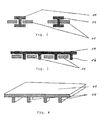
- Fig. 2 are designed as individual elements support elements 14 are shown.
- the support member 14 In the left half of the Fig. 2 the support member 14 is movably mounted in the board 11. In the right half of the Fig. 2 the support member 14 is fixed in the board 11, for example via a fit or by gluing.
- the Fig. 3 It comprises a support plate for large-area load bearing and the support of the board 11 via via openings in the board 11 by cross-supporters 16, which may be formed, for example point or line-shaped and are supported on the cell assembly 6.
- the Fig. 4 shows a board 11 with integrated support elements 14, whose expansion is dimensioned as needed and which may for example also be support eyes or components of the board 11, for example coils.
Landscapes
- Chemical & Material Sciences (AREA)
- Chemical Kinetics & Catalysis (AREA)
- Electrochemistry (AREA)
- General Chemical & Material Sciences (AREA)
- Battery Mounting, Suspending (AREA)
Description
- Die Erfindung betrifft eine Batterie, insbesondere eine Lithium-Ionen-Batterie oder Nickel-Metallhydrid-Batterie, insbesondere eine Fahrzeugbatterie, insbesondere eine Batterie für ein Fahrzeug mit Hybridantrieb oder ein Brennstoffzellen-Fahrzeug, insbesondere eine Hochvolt-Batterie.
- Nach dem Stand der Technik muss die bei Ladung und Entladung in den Zellen von Lithium-Ionen-Batterien (z.B. für Hybridantriebe oder Brennstoffzellen-Fahrzeuge) entstehende Wärme durch eine Kühlung abgeführt werden. Wegen der maximal zulässigen Zelltemperatur von ca. 50 °C wird die Kühlung über den Klimakreislauf des Fahrzeugs vorgenommen.
- Nach dem Stand der Technik sind Batterien bekannt, bei denen Zellen vom Boden aus durch eine von Kältemittel durchströmte Kühlplatte gekühlt werden. In Längsrichtung der Zelle wird die Wärme durch separate Wärmeleitstäbe geleitet. Um die Wärme von den Zellen zu der Kühlplatte zu leiten befinden sich zwischen den Zellen Wärmeleitstäbe aus Aluminium, die in der Kühlplatte verankert sind und die Wärme in Längsrichtung der Zellen ableiten. Allerdings ist eine derartige mit Wärmeleitstäben versehene Kühlplatte und ebenso ein Hüllblech aufwendig und teuer. Die wärmetechnische Anbindung der Zellen an die Wärmeleitstäbe erfolgt durch Vergussmasse, mit welcher der Zellverbund ausgegossen ist. Die Vergussmasse übernimmt gleichzeitig die elektrische Isolation und fixiert die Zellen im Zellverbund. Ferner gleicht die Vergussmasse toleranzbedingte Spalten zwischen den Bauteilen des Zellverbunds aus. Als Vergussmasse wird beispielsweise Epoxydharz, Polyurethan oder Silikon verwendet. Die Vergussmasse besitzt somit gegenüber den sonstigen Bauteilen des Zellverbunds nur eine relativ geringe mechanische Festigkeit.
- Auf die Kühlplatte ist außerdem ein mantelartiges Blech aufgesetzt, das die Zellen seitlich umschließt. Es dient zur Wärmeableitung und als Form für die Vergussmasse, mit der die Räume zwischen Zellen und Wärmeleitstäben ausgegossen werden. Der ganze Zellblock ist mit dem Hüllblech umgeben und wird mittels einer wärmeleitfähigen Vergussmasse ausgegossen. Dabei bildet das Hüllblech gleichzeitig die Vergießform.
- Nach dem Verguss entsteht der so genannte Zellblock oder Zellverbund, eine massive Konstruktion, die im Batteriegehäuse befestigt wird. Nach dem Einbau des Innenlebens der Batterie wird der Gehäusedeckel durch Verschraubung, Vernietung, Verklebung oder Verschweißung befestigt. Das Gehäuse einer Batterie umfasst also typischerweise einen Boden, eine Seitenwand und einen Deckel.
- Zum Verbinden der elektrischen Anschlußbereiche der Zellen sowie ggf. zum Überwachen der Funktion, z.B. Laden oder Stromentnahme, der Zellen einer Batterie, auf die sich die vorliegende Anmeldung bezieht, weist die Batterie eine Platine (Zellverbindungs- und/oder Überwachungsplatine) auf, die im Innern des Gehäuses im elektrischen Anschlussbereich der Zellen angeordnet ist.
- Eine Platine ist ein Trägerelement für elektronische Bauteile. Sie wird auch als Leiterplatte oder gedruckte Schaltung bezeichnet und dient der mechanischen Befestigung und der elektrischen Verbindung von elektronischen Bauteilen. Die Verbindungsleitungen werden in der Regel durch Ätzen aus einer dünnen Schicht leitfähigen Materials auf einer isolierenden Grundplatte hergestellt und die Bauelemente werden auf diese Leiterbahnen gelötet.
- Die Platine ist aufgrund ihrer Bauart ein bruchempfindliches Teil und wird daher im Deformationsfall des Gehäuses, z.B. bei einem Frontalcrash eines Kraftfahrzeugs mit einer entsprechenden Batterie, Belastungskräften ausgesetzt, die von der Deformationskraft auf das Gehäuse verursacht werden. Dadurch kann die Platine beschädigt oder zerstört werden, was auch Gefahren mit sich bringt. Beispielsweise können hohe Kurzschlussströme zu Überhitzungen führen oder Lichtbögen zu der Entzündung von Gemischen. Bei Hochvoltbatterien besteht auch die Gefahr, dass das Gehäuse unter Spannung gesetzt wird.
- Nach dem Stand der Technik werden zum Schutz der Platinen in Batterien Isolationsplatten eingesetzt, die lediglich eine direkte Berührung von Gehäuse und stromführenden Teilen im Inneren des Gehäuses verhindern. Dabei kommt es zu Deformationen der Zellen einschließlich des Zellterminals und des Gehäuses und dem Abreißen von Zellverbindern. Da bei Hochvoltbatterien eine Spannung von ca. 120 Volt oder mehr vorliegt, kommt es zur Ausbildung von Lichtbögen und/oder zu einer Überlastung der Zellen.
- Nachteilig bei den bekannten Batterien ist somit die hohe Belastung, die im Deformationsfall von dem Gehäuse auf die Platine wirkt und dadurch zu Schädigungen, Zerstörungen und Gefahren führen kann.
- Der Erfindung liegt die Aufgabe zugrunde, eine Batterie mit einer verbesserten Deformationssicherheit, beispielsweise im Crashfall, zu schaffen.
- Die Aufgabe wird erfindungsgemäß durch eine Batterie mit den Merkmalen des Anspruchs 1 gelöst. Bevorzugte Ausgestaltungen und Weiterbildungen der Erfindung ergeben sich aus den abhängigen Ansprüchen und der nachfolgenden Beschreibung mit zugehörigen Zeichnungen.
- Ein erfindungsgemäße Batterie, insbesondere eine Lithium-Ionen-Batterie oder Nickel-Metallhydrid-Batterie, mit einem Gehäuse, einem in dem Gehäuse angeordneten Zellverbund aus Batteriezellen und einer Platine, die im Innern des Gehäuses im elektrischen Anschlussbereich der Zellen zum elektrischen Verbinden der Zellen angeordnet ist, weist also die Besonderheit auf, dass die Batterie im Innern des Gehäuses angeordnete Stützelemente aufweist, mit denen im Falle einer Deformation des Gehäuses durch eine von außen auf das Gehäuse einwirkende Deformationskraft, die zu einem Deformieren des Gehäuses in Richtung auf die Platine führt, die durch die Deformation des Gehäuses von dem Gehäuse auf die Platine ausgeübten Belastungskräfte zum Schutz der Platine abgestützt werden.
- Die Stützelemente sind dabei vorteilhafterweise zum Vorbeiführen der Belastungskräfte um die Platine oder zum Hindurchführen der Belastungskräfte durch die Platine ausgebildet.
- Eine vorteilhafte Ausführungsform besteht darin, dass die Stützelemente für die Kraftverteilung zum Absetzen mittels durch die Platine durchgehender Stützelementen auf dem Zellverbund ausgebildet sind. Die Stützelemente können für die Kraftverteilung zum großflächigen Absetzen des Gehäuses auf dem Zellverbund oder für die Kraftverteilung zum Absetzen mittels durch die Platine durchgehender Stützelemente auf dem Zellverbund ausgebildet sein.
- Nach einem vorteilhaften Merkmal ist vorgesehen, dass die Stützelemente zum Ableiten der Belastungskräfte auf die der Platine zugewandte Seite des Zellverbunds ausgebildet sind.
- Gemäß einer ersten vorteilhaften Weiterbildung ist vorgesehen, dass die Kraftleitung der Belastungskräfte mittels in der Platine beweglich eingelagerter Stützelemente erfolgt. Die Kraftleitung der Belastungskräfte kann aber auch mittels in der Platine fixierter Stützelemente erfolgen, wobei die Stützelemente beispielsweise durch eine Passung in der Platine fixiert oder in die Platine eingeklebt sind.
- Die Stützelemente können vorteilhafterweise als Einzelelemente, beispielsweise als Stifte, oder als Flächenelement, beispielsweise als Platte, ausgebildet sein. Die Platte ist vorteilhafterweise auf der von dem elektrischen Anschlussbereich der Zellen abgewandten Seite der Platine angeordnet. Ferner kann die Platte die Platine durchdringende Stützen aufweisen.
- Eine andere vorteilhafte Ausführungsform besteht darin, dass Platine zur Kraftleitung der Belastungskräfte auf der Platine eingearbeitete oder in die Platine integrierte Stützelemente aufweist. Dabei können die Stützelemente beispielsweise als Stützaugen oder als stabile elektrische Bauelemente, die auf der Platine angeordnet, beispielsweise Spulen, ausgebildet sein. Ferner können die Stützelemente auf der Seite der Platine angeordnet sein, die dem elektrischen Anschlussbereich der Zellen zugewandt ist, oder sowohl auf der Seite der Platine, die dem elektrischen Anschlussbereich der Zellen zugewandt ist, als auch auf der Seite der Platine, die von dem elektrischen Anschlussbereich der Zellen abgewandt ist, angeordnet sein.
- Vorteilhafte Ausführungsformen bestehen darin, dass Stützelemente zur punktuellen, linienförmigen oder flächigen Lastverteilung innerhalb der Batterie ausgebildet sind.
- Eine weitere vorteilhafte Ausgestaltung ist darin zu sehen, dass die Stützelemente zum Abstützen einer im wesentlichen waagrecht verlaufenden Deformationskraft bzw. Belastungskraft ausgebildet und hierzu im wesentlichen in waagrechter Orientierung, bezogen auf die Einbaulage der Batterie, ausgerichtet sind.
- Durch die Erfindung werden folgende Vorteile erzielt:
- Auch bei einem Crash wird die elektrische Sicherheit durch eine Verteilung der Kraft innerhalb des Zellverbunds gewährleistet.
- Die Batterie kann in crashgefährdeten Bauräumen, beispielsweise eines Kraftfahrzeugs, eingebaut werden.
- Die Zell-Polanschlüsse werden geschützt.
- Die Zellverbinderplatinen werden vor Beschädigung oder Zerstörung geschützt, auch im Hinblick auf Leiterbahnen und Bauelemente.
- Zusätzliche aufwendige Verstärkungsmaßnahmen an dem Gehäuse können entfallen.
- Eine Hochvolt-Batterie für ein Hybrid-Kraftfahrzeug wird im Deformationsfall, z.B. beim Frontalcrash, nicht durch einen Kontakt zwischen Zellverbinder-Platinen und Batteriegehäuse eine elektrische Spannung auf dem Gehäuse führen.
- Die Gesamtdeformation wird sehr gering gehalten und Zellpole werden beim Kontakt des Batteriegehäuses mit der Zellverbinder-Platine nicht deformiert.
- Die Belastungskraft wird über einen breiten Zellverbund durch die Batterie geführt. Dadurch wird die Struktur des Batteriegehäuses entlastet.
- Kräfte können durch Platinen ohne deren Zerstörung oder Beschädigung mittels Stützelementen durchgeleitet werden.
- Das elektrische Layout von Zellverbinderplatinen wird geschützt. Die elektrische Isolation wird gewährleistet.
- Im Zellverbund werden zur Vermeidung von Kraftspitzen Druckkräfte aus dem Batteriegehäuse aufgenommen.
- Die Zellterminals werden vor Verformung, Beschädigung oder Zerstörung mittels Stützelementen zwischen Batteriegehäuse, Zellverbinder-Platine und Zellverbund geschützt.
- Elektrische Energiespeicher auf Zellbasis, z.B. Batteriezellen und Kondensatoren, werden in crashrelevenaten Fahrzeugzonen durch eine Kraftverteilung mittels Stützelementen innerhalb des Batteriegehäuses unter Nutzung des Zellverbundes zur Kraftübertragung geschützt.
- Stützelemente werden zur punktuellen, linienförmigen oder flächigen Lastverteilung innerhalb einer Batterie zu deren elektrischer und mechanischer Sicherheit und Stabilität eingesetzt.
- Stützelemente, die Bestandteil eines Platinendesigns sind oder separat Kräfte durch Platinen führen können, können als Crash-Schutzelemente genutzt werden.
- Die Erfindung wird nachfolgend anhand in den Figuren dargestellter Ausführungsbeispiele näher erläutert. Die darin beschriebenen Besonderheiten können einzeln oder in Kombination miteinander eingesetzt werden, um bevorzugte Ausgestaltungen der Erfindung zu schaffen.
- Dabei zeigen:
- Fig. 1
- einen senkrechten Schnitt durch eine erfindungsgemäße Batterie.
- Fig. 2
- als Einzelelemente ausgebildete Stützelemente.
- Fig. 3
- ein als Flächenelement ausgebildetes Stützelement.
- Fig. 4
- eine Platine mit integrierten Stützelmenten.
- Die
Fig. 1 zeigt einen senkrechten Schnitt durch eine erfindungsgemäße Batterie 1. Zu erkennen sind in das Gehäuse 2, das ein Innengehäuse 3 und ein Außengehäuse 4 umfasst, eingesetzte Zellen 5, beispielsweise Lithium-Ionen-Batteriezellen. Die Zellen 5 haben eine kreiszylindrische Außenkontur und sind mit den Längsachsen parallel zueinander in einem Zellverbund 6 angeordnet. Zum Erzielen einer raumsparenden Bauform sind die Zellen 5 in einer kompakten regelmäßigen Anordnung, ggf. mit einem geringen Abstand zwischen den Zellen 5, nebeneinander in dem Zellverbund 5 angeordnet. Die Zellen 5 können vom Boden aus durch eine von Kältemittel durchströmte Kühlplatte 7 gekühlt werden, die in intern verlegten Kühlschlangen von Kältemittel durchströmt wird. Zum Durchleiten einer Kühlflüssigkeit durch die Kühlschlange der Kühlplatte 7 weist die Kühlplatte 7 einen Kühlflüssigkeitsanschluss auf. - Der ganze Zellblock 5 kann mit einem Hüllblech umgeben sein und kann vor oder nach dem Einsetzen in das Batteriegehäuse 2 mit wärmeleitfähiger Vergussmasse 8 ausgegossen sein, die in
Fig. 1 noch nicht eingefüllt ist. Die Vergussmasse 8 übernimmt gleichzeitig die elektrische Isolation und fixiert die Zellen 5 im Zellverbund 6. Der Zellverbund 6 ist durch Gegenlager 9 gegen das Gehäuse 2 abgestützt. - Die zwischen den Zellen 5 vorhandenen Spalten bzw. Zwischenräume werden mit Vergussmasse 8 ausgefüllt. Das Hüllblech dient gleichzeitig als Gießform beim Einfüllen der Vergussmasse 8. Der beim Vergießen mit Vergussmasse 8 gebildete Zellverbund 6 wird nach dem Verguss in das Batteriegehäuse 2 eingebaut. Geeignete Werkstoffe für die Vergussmasse 8 sind beispielsweise ein Epoxydharz, oder ein Hartschaum bzw. aushärtender Schaum, insbesondere ein Polyurethan-Schaum. Die Vergussmasse 8 ist vorzugsweise ein wärmeleitfähiges und/oder elektrisch isolierendes Material.
- In dem elektrischen Anschlussbereich 10 der Zellen 5 ist eine Platine 11 (Zellverbindungsplatine) angeordnet. Es kann vorgesehen sein, dass die dem Gehäuse 2 zugewandte Seite der Platine 11 mit einer Vergussmasse 8 ausgegossen ist.
- Wenn eine externe Deformationskraft 12 auf das Batteriegehäuse 2 einwirkt, wird dieses deformiert. Die Deformation 13 des Gehäuses 2 ist durch die gestrichelte Linie angedeutet. Aufgrund der Deformation 13 kommt es zu einem Kontakt mit im Inneren des Batteriegehäuses 2 angeordneten Batteriebestandteilen, auf die eine von der Deformation 13 ausgehende Belastungskraft ausgeübt wird. Erfindungsgemäß ist vorgesehen, zum Ableiten dieser Belastungskräfte Stützelemente 14 vorzusehen, die in dem dargestellten Ausführungsbeispiel beispielsweise Durchleitungsstifte oder Stützaugen sind. Hierdurch wird die Belastungskraft von der Platine 11 ferngehalten und diese somit geschützt. Es resultiert ein beispielhaft eingezeichneter Kraftpfad 15.
- Es wird vorgeschlagen, die über das Batteriegehäuse 2 partiell eingeleitete Deformationskraft 12 an der Platine 11 vorbeizuführen oder durch die Platine 11 hindurchzuführen und das Gehäuse 2 zur Kraftverteilung großflächig auf dem Zellverbund 6 bzw. durchgehenden Stützelementen 14 abzusetzen. Die Kraftleitung erfolgt entweder über in der Platine 11 bewegliche eingelagerte Stifte oder Platten oder über auf den Platinen bereits eingearbeitete Stützaugen oder über stabile elektrische Bauelemente wie Spulen. Im Fall der eingearbeiteten Stützaugen kann die Platine 11 diese beidseitig besitzen oder die dem Gehäuse 2 zugewandte Seite ist z.B. durch Vergussmasse 8 elektrisch und Mechanisch geschützt, um großflächig die Gehäusekraft aufnehmen zu können.
- In
Fig. 2 sind als Einzelelemente ausgebildete Stützelemente 14 dargestellt. In der linken Hälfte derFig. 2 ist das Stützelement 14 beweglich in der Platine 11 gelagert. In der rechten Hälfte derFig. 2 ist das Stützelement 14 in der Platine 11 fixiert, beispielsweise über eine Passung oder durch Einkleben. - Die
Fig. 3 zeigt ein als Flächenelement ausgebildetes Stützelement 14. Es umfasst eine Stützplatte zur großflächigen Lastaufnahme und die Abstützung der Platine 11 erfolgt über durch Öffnungen in der Platine 11 hindurchgreifende Stützen 16, die beispielsweise punkt- oder linienförmig ausgebildet sein können und sich auf dem Zellverbund 6 abstützen. - Die
Fig. 4 zeigt eine Platine 11 mit integrierten Stützelemente 14, deren Ausdehnung nach Bedarf bemessen ist und bei denen es sich beispielsweise auch um Stützaugen oder um Bauelemente der Platine 11, beispielsweise Spulen handeln kann.
Claims (12)
- Batterie (1), insbesondere eine Lithium-Ionen-Batterie oder Nickel-Metallhydrid-Batterie, mit einem Gehäuse (2), einem in dem Gehäuse (2) angeordneten Zellverbund (6) aus Batteriezellen (5) und einer Platine (11), die im Innern des Gehäuses (2) im elektrischen Anschlussbereich (10) der Zellen zum elektrischen Verbinden der Zellen (5) angeordnet ist,
dadurch gekennzeichnet, dass
die Batterie (1) im Innern des Gehäuses (2) angeordnete Stützelemente (14) aufweist, mit denen im Falle einer Deformation (13) des Gehäuses (2) durch eine von außen auf das Gehäuse (2) einwirkende Deformationskraft (12), die zu einem Deformieren des Gehäuses (2) in Richtung auf die Platine (11) führt, die durch die Deformation (13) des Gehäuses (2) von dem Gehäuse (2) auf die Platine (11) ausgeübten Belastungskräfte zum Schutz der Platine (11) abgestützt werden,
dass die Stützelemente (14) zum Vorbeiführen der Belastungskräfte um die Platine (11) und/oder zum Hindurchführen der Belastungskräfte durch die Platine (11) ausgebildet sind und
dass die Stützelemente (14) für die Kraftverteilung zum großflächigen Absetzen des Gehäuses (2) auf dem Zellverbund (6) ausgebildet sind - Batterie (1) nach Anspruch 1, dadurch gekennzeichnet, dass die Stützelemente (14) zum Ableiten der Belastungskräfte auf die der Platine (11) zugewandte Seite des Zellverbunds (6) ausgebildet sind.
- Batterie (1) nach Anspruch 1, dadurch gekennzeichnet, dass die Kraftleitung der Belastungskräfte mittels in der Platine (11) beweglich eingelagerter Stützelemente (14) erfolgt und/oder dass die Kraftleitung der Belastungskräfte mittels in der Platine (11) fixierter Stützelemente (14) erfolgt.
- Batterie (1) nach Anspruch 1, dadurch gekennzeichnet, dass die Stützelemente (14) als Platte ausgebildet sind.
- Batterie (1) nach Anspruch 4, dadurch gekennzeichnet, dass die Platte auf der von dem elektrischen Anschlussbereich der Zellen abgewandten Seite der Platine (11) angeordnet ist.
- Batterie (1) nach Anspruch 4 oder 5, dadurch gekennzeichnet, dass die Platte die Platine (11) durchdringende Stützen (16) aufweist.
- Batterie (1) nach Anspruch 1, dadurch gekennzeichnet, dass die Platine (11) zur Kraftleitung der Belastungskräfte auf der Platine (11) eingearbeitete oder in die Platine (11) integrierte Stützelemente (14) aufweist.
- Batterie (1) nach Anspruch 1, dadurch gekennzeichnet, dass die Stützelemente (14) auf der Seite der Platine (11) angeordnet sind, die dem elektrischen Anschlussbereich (10) der Zellen (5) zugewandt ist.
- Batterie (1) nach Anspruch 1, dadurch gekennzeichnet, dass die Stützelemente (14) sowohl auf der Seite der Platine (11), die dem elektrischen Anschlussbereich (10) der Zellen (5) zugewandt ist, als auch auf der Seite der Platine (11), die von dem elektrischen Anschlussbereich (10) der Zellen (5) abgewandt ist, angeordnet sind.
- Batterie (1) nach Anspruch 1, dadurch gekennzeichnet, dass die Stützelemente (14) zur flächigen Lastverteilung innerhalb der Batterie (1) ausgebildet sind.
- Batterie (1) nach Anspruch 1, dadurch gekennzeichnet, dass die dem Gehäuse (2) zugewandte Seite der Platine (11) mit einer Vergussmasse (8) ausgegossen ist.
- Batterie (1) nach Anspruch 1, dadurch gekennzeichnet, dass die Stützelemente (14) zum Abstützen einer im wesentlichen waagrecht verlaufenden Deformationskraft (12) bzw. Belastungskraft ausgebildet und hierzu im wesentlichen in waagrechter Orientierung, bezogen auf die Einbaulage der Batterie (1), ausgerichtet sind.
Applications Claiming Priority (2)
| Application Number | Priority Date | Filing Date | Title |
|---|---|---|---|
| DE102007010738A DE102007010738B4 (de) | 2007-02-27 | 2007-02-27 | Leiterplattenschutz für eine Batterie und Verwendung der Batterie |
| PCT/EP2008/001447 WO2008104340A1 (de) | 2007-02-27 | 2008-02-23 | Leiterplattenschutz für eine batterie |
Publications (2)
| Publication Number | Publication Date |
|---|---|
| EP2130416A1 EP2130416A1 (de) | 2009-12-09 |
| EP2130416B1 true EP2130416B1 (de) | 2013-02-13 |
Family
ID=39432696
Family Applications (1)
| Application Number | Title | Priority Date | Filing Date |
|---|---|---|---|
| EP08715998A Active EP2130416B1 (de) | 2007-02-27 | 2008-02-23 | Leiterplattenschutz für eine batterie |
Country Status (4)
| Country | Link |
|---|---|
| US (1) | US20100173191A1 (de) |
| EP (1) | EP2130416B1 (de) |
| DE (1) | DE102007010738B4 (de) |
| WO (1) | WO2008104340A1 (de) |
Families Citing this family (29)
| Publication number | Priority date | Publication date | Assignee | Title |
|---|---|---|---|---|
| DE102007063187B3 (de) * | 2007-12-20 | 2009-04-02 | Daimler Ag | Batterie mit einer Kühlplatte und Verfahren zur Herstellung einer Batterie |
| DE102009006991B4 (de) * | 2009-01-31 | 2013-08-01 | Audi Ag | Elektrischer Energiespeicher für Kraftfahrzeuge |
| DE102009030017A1 (de) * | 2009-06-23 | 2010-12-30 | Bayerische Motoren Werke Aktiengesellschaft | Vorrichtung zur Spannungsversorgung eines Kraftfahrzeugs mit einem Kühlerblock |
| DE102009030016A1 (de) | 2009-06-23 | 2010-12-30 | Bayerische Motoren Werke Aktiengesellschaft | Vorrichtung zur Spannungsversorung eines Kraftfahrzeugs mit einem Kühlerblock |
| DE102009040128B4 (de) * | 2009-09-04 | 2014-04-30 | Tq-Systems Gmbh | Batteriepack und Verfahren zum Herstellen eines Batteriepacks |
| DE102012102657A1 (de) * | 2012-03-28 | 2013-10-02 | Dr. Ing. H.C. F. Porsche Aktiengesellschaft | Traktionsbatterie und Kraftfahrzeug mit einer solchen Traktionsbatterie |
| DE102012015817B4 (de) | 2012-08-10 | 2024-01-18 | Dr. Ing. H.C. F. Porsche Ag | Kraftfahrzeugbatterie |
| DE102013202288A1 (de) | 2013-02-13 | 2014-08-14 | Robert Bosch Gmbh | Batteriezelle mit einem ein elastisch federndes Element aufweisenden Arretierkörper |
| DE102013011892B4 (de) * | 2013-07-16 | 2023-06-01 | Audi Ag | Kühlvorrichtung für eine Batterie eines Kraftfahrzeugs, Batterie mit einer solchen Kühlvorrichtung sowie Herstellungsverfahren |
| DE102013021234A1 (de) | 2013-12-14 | 2015-06-18 | Daimler Ag | Batterie |
| US10020475B2 (en) | 2014-06-04 | 2018-07-10 | Ford Global Technologies, Llc | Battery assembly reinforcement member |
| US9608245B2 (en) | 2014-09-30 | 2017-03-28 | Johnson Controls Technology Company | System for providing structural integrity of a battery module |
| WO2018033880A2 (en) | 2016-08-17 | 2018-02-22 | Shape Corp. | Battery support and protection structure for a vehicle |
| WO2018127832A1 (en) | 2017-01-04 | 2018-07-12 | Shape Corp. | Vehicle battery tray structure with nodal modularity |
| US10886513B2 (en) | 2017-05-16 | 2021-01-05 | Shape Corp. | Vehicle battery tray having tub-based integration |
| WO2018213383A1 (en) | 2017-05-16 | 2018-11-22 | Shape Corp. | Vehicle battery tray with integrated battery retention and support features |
| WO2018213475A1 (en) | 2017-05-16 | 2018-11-22 | Shape Corp. | Polarized battery tray for a vehicle |
| US12347879B2 (en) | 2017-09-13 | 2025-07-01 | Shape Corp. | Vehicle battery tray with tubular peripheral wall |
| WO2019055658A2 (en) | 2017-09-13 | 2019-03-21 | Shape Corp. | VEHICLE BATTERY TRAY WITH TUBULAR PERIPHERAL WALL |
| WO2019071013A1 (en) | 2017-10-04 | 2019-04-11 | Shape Corp. | BATTERY SUPPORT BOTTOM ASSEMBLY FOR ELECTRIC VEHICLES |
| EP3759761B1 (de) | 2018-03-01 | 2026-04-08 | Shape Corp. | In fahrzeugbatteriefach integriertes kühlsystem |
| US11688910B2 (en) | 2018-03-15 | 2023-06-27 | Shape Corp. | Vehicle battery tray having tub-based component |
| FR3091956B1 (fr) * | 2019-01-22 | 2023-10-20 | Valeo Systemes Thermiques | Dispositif de stockage d'énergie électrique pour véhicule automobile |
| DE102019209448A1 (de) * | 2019-06-28 | 2020-12-31 | Volkswagen Aktiengesellschaft | Batteriemodul |
| US12040501B2 (en) | 2020-02-12 | 2024-07-16 | Ford Global Technologies, Llc | Impact protection shrouds for protecting battery pack components |
| DE102021123176A1 (de) | 2021-09-07 | 2023-03-09 | MTU Aero Engines AG | Brennstoffzellenvorrichtung und Endplatte für eine Brennstoffzellenvorrichtung |
| EP4454057A4 (de) * | 2021-12-22 | 2026-02-25 | Bridgestone Americas Inc | Verbundbatteriegehäuse mit äusseren stosskomponenten |
| DE102022128444A1 (de) * | 2022-10-27 | 2024-05-02 | Bayerische Motoren Werke Aktiengesellschaft | Elektrische Energiespeichereinrichtung und Kraftfahrzeug |
| DE102024110334A1 (de) * | 2024-04-12 | 2025-10-16 | Bayerische Motoren Werke Aktiengesellschaft | Speicherzellen-Anordnung mit einer Druckentlastungskomponente |
Family Cites Families (17)
| Publication number | Priority date | Publication date | Assignee | Title |
|---|---|---|---|---|
| US3383565A (en) * | 1966-05-13 | 1968-05-14 | Gen Electric | Packaging of electrical components |
| US3988170A (en) * | 1975-06-30 | 1976-10-26 | Aktiebolaget Tudor | Battery cases |
| US4828939A (en) * | 1987-06-01 | 1989-05-09 | Eltech Systems Corporation | Bipolar metal/air battery |
| US5123538A (en) * | 1991-04-26 | 1992-06-23 | Sundstrand Corporation | Crash protection enclosure for solid state memory devices |
| US5851695A (en) * | 1992-02-10 | 1998-12-22 | C & D Technologies, Inc. | Recombinant lead-acid cell and long life battery |
| US5259786A (en) * | 1992-06-29 | 1993-11-09 | Londa Photo Products Co., Ltd. | Lamp unit battery seat |
| GB2302994B (en) * | 1995-07-01 | 1999-06-09 | British Aerospace | Thermal and shock resistant data recorder assembly |
| US6255015B1 (en) * | 1998-08-23 | 2001-07-03 | Ovonic Battery Company, Inc. | Monoblock battery assembly |
| GB2351612A (en) * | 1999-06-26 | 2001-01-03 | Rover Group | Mounting batteries on printed circuit boards |
| US7459882B2 (en) * | 2000-03-06 | 2008-12-02 | Richard Morgan | Rechargeable batteries |
| US20020187807A1 (en) * | 2001-06-07 | 2002-12-12 | Torre Richard D. La | Clip-on/clip-in smart module |
| AU2003270618A1 (en) * | 2002-09-12 | 2004-04-30 | Metallic Power, Inc. | Current feeders for electrochemical cell stacks |
| US6880243B2 (en) * | 2002-10-04 | 2005-04-19 | Sanmina-Sci Corporation | Stiffener for stiffening a circuit board |
| US6943292B2 (en) * | 2003-05-12 | 2005-09-13 | Siemens Vdo Automotive Corporation | Printed circuit board stiffener |
| US7163287B2 (en) * | 2004-01-21 | 2007-01-16 | Silverbrook Research Pty Ltd | Combined cutter and slitter module for a printer |
| CN100561773C (zh) * | 2005-02-18 | 2009-11-18 | 丰田自动车株式会社 | 电池组 |
| JP4413888B2 (ja) * | 2006-06-13 | 2010-02-10 | 株式会社東芝 | 蓄電池システム、車載電源システム、車両、および蓄電池システムの充電方法 |
-
2007
- 2007-02-27 DE DE102007010738A patent/DE102007010738B4/de not_active Expired - Fee Related
-
2008
- 2008-02-23 WO PCT/EP2008/001447 patent/WO2008104340A1/de not_active Ceased
- 2008-02-23 US US12/528,752 patent/US20100173191A1/en not_active Abandoned
- 2008-02-23 EP EP08715998A patent/EP2130416B1/de active Active
Also Published As
| Publication number | Publication date |
|---|---|
| US20100173191A1 (en) | 2010-07-08 |
| DE102007010738B4 (de) | 2012-01-26 |
| EP2130416A1 (de) | 2009-12-09 |
| WO2008104340A1 (de) | 2008-09-04 |
| DE102007010738A1 (de) | 2008-08-28 |
Similar Documents
| Publication | Publication Date | Title |
|---|---|---|
| EP2130416B1 (de) | Leiterplattenschutz für eine batterie | |
| DE102007010742B4 (de) | Zellverbund einer Batterie, Batterie und deren Verwendung | |
| DE102007017018A1 (de) | Überbrückung defekter Zellen bei Batterien | |
| WO2009080166A1 (de) | Batterie mit mehreren paralell und/oder seriell miteinander verschalteten einzelzellen und einer wärmeleitplatte zum temperieren der batterie | |
| EP2269247A1 (de) | Batterie mit einer wärmeleitplatte und mehreren einzelzellen | |
| DE102007045183A1 (de) | Temperierte Batterieeinrichtung und Verfahren hierzu | |
| DE102008010828A1 (de) | Batterie mit mehreren Einzelzellen | |
| DE102007010744A1 (de) | Batteriezelle und Zellverbund einer Batterie | |
| DE102008034870B4 (de) | Batterie mit mehreren Batteriezellen und Verfahren zur Herstellung einer Batterie | |
| DE102018218865A1 (de) | Gehäuse für eine Batteriezelle, Batteriezelle und Verfahren zum Herstellen derselben | |
| DE102012224330A1 (de) | Elektrische Akkumulatorvorrichtung mit elastischen Elementen | |
| WO2020030651A1 (de) | Batteriegehäuse, batteriesystem und montageverfahren für ein batteriesystem | |
| DE102020003870A1 (de) | Verfahren und Vorrichtung zur Reparatur einer Batterie | |
| EP3465797B1 (de) | Batterie mit batterieabschnitten und kontaktierungsabschnittselement | |
| DE102011078235B4 (de) | Kontaktelement zum mechanischen, thermischen und elektrischen Kontaktieren eines Energiespeichers | |
| EP2606522A1 (de) | Elektrochemische zelle mit wenigstens einer druckentlastungsvorrichtung | |
| WO2016120359A1 (de) | Batteriezelle und batteriesystem | |
| DE202024107543U1 (de) | Batteriepack | |
| DE102019215335A1 (de) | Zellgehäuse zur Anordnung von Batteriezellen | |
| EP2823518B1 (de) | Batterie für ein fahrzeug und verfahren zum fertigen einer solchen batterie | |
| WO2019091633A1 (de) | Elektrische energiespeicherzelle mit isolierender hülle | |
| DE102023130538B3 (de) | Verfahren zum Verschalten von Batteriezellen unter Einhaltung von Luft und Kriechstrecken | |
| DE102022106987B4 (de) | Batterie mit mehrseitiger Kühlung, Antriebssystem und Kraftfahrzeug | |
| DE102024122215A1 (de) | Modulare Batteriezelle | |
| DE102024117687A1 (de) | Trägerplatte für eine Zellkontaktierungseinrichtung eines Hochvoltspeichers |
Legal Events
| Date | Code | Title | Description |
|---|---|---|---|
| PUAI | Public reference made under article 153(3) epc to a published international application that has entered the european phase |
Free format text: ORIGINAL CODE: 0009012 |
|
| 17P | Request for examination filed |
Effective date: 20090912 |
|
| AK | Designated contracting states |
Kind code of ref document: A1 Designated state(s): AT BE BG CH CY CZ DE DK EE ES FI FR GB GR HR HU IE IS IT LI LT LU LV MC MT NL NO PL PT RO SE SI SK TR |
|
| 17Q | First examination report despatched |
Effective date: 20100323 |
|
| DAX | Request for extension of the european patent (deleted) | ||
| REG | Reference to a national code |
Ref country code: DE Ref legal event code: R079 Ref document number: 502008009228 Country of ref document: DE Free format text: PREVIOUS MAIN CLASS: H05K0001020000 Ipc: H01M0002020000 |
|
| RIC1 | Information provided on ipc code assigned before grant |
Ipc: H05K 1/02 20060101ALI20120711BHEP Ipc: B60R 21/0136 20060101ALI20120711BHEP Ipc: H01M 2/10 20060101ALI20120711BHEP Ipc: H01M 2/02 20060101AFI20120711BHEP |
|
| GRAP | Despatch of communication of intention to grant a patent |
Free format text: ORIGINAL CODE: EPIDOSNIGR1 |
|
| GRAS | Grant fee paid |
Free format text: ORIGINAL CODE: EPIDOSNIGR3 |
|
| GRAA | (expected) grant |
Free format text: ORIGINAL CODE: 0009210 |
|
| AK | Designated contracting states |
Kind code of ref document: B1 Designated state(s): AT BE BG CH CY CZ DE DK EE ES FI FR GB GR HR HU IE IS IT LI LT LU LV MC MT NL NO PL PT RO SE SI SK TR |
|
| REG | Reference to a national code |
Ref country code: GB Ref legal event code: FG4D Free format text: NOT ENGLISH |
|
| REG | Reference to a national code |
Ref country code: AT Ref legal event code: REF Ref document number: 596898 Country of ref document: AT Kind code of ref document: T Effective date: 20130215 |
|
| REG | Reference to a national code |
Ref country code: IE Ref legal event code: FG4D Free format text: LANGUAGE OF EP DOCUMENT: GERMAN |
|
| REG | Reference to a national code |
Ref country code: DE Ref legal event code: R096 Ref document number: 502008009228 Country of ref document: DE Effective date: 20130411 |
|
| REG | Reference to a national code |
Ref country code: NL Ref legal event code: VDEP Effective date: 20130213 |
|
| REG | Reference to a national code |
Ref country code: LT Ref legal event code: MG4D |
|
| PG25 | Lapsed in a contracting state [announced via postgrant information from national office to epo] |
Ref country code: SE Free format text: LAPSE BECAUSE OF FAILURE TO SUBMIT A TRANSLATION OF THE DESCRIPTION OR TO PAY THE FEE WITHIN THE PRESCRIBED TIME-LIMIT Effective date: 20130213 Ref country code: LT Free format text: LAPSE BECAUSE OF FAILURE TO SUBMIT A TRANSLATION OF THE DESCRIPTION OR TO PAY THE FEE WITHIN THE PRESCRIBED TIME-LIMIT Effective date: 20130213 Ref country code: BG Free format text: LAPSE BECAUSE OF FAILURE TO SUBMIT A TRANSLATION OF THE DESCRIPTION OR TO PAY THE FEE WITHIN THE PRESCRIBED TIME-LIMIT Effective date: 20130513 Ref country code: IS Free format text: LAPSE BECAUSE OF FAILURE TO SUBMIT A TRANSLATION OF THE DESCRIPTION OR TO PAY THE FEE WITHIN THE PRESCRIBED TIME-LIMIT Effective date: 20130613 Ref country code: ES Free format text: LAPSE BECAUSE OF FAILURE TO SUBMIT A TRANSLATION OF THE DESCRIPTION OR TO PAY THE FEE WITHIN THE PRESCRIBED TIME-LIMIT Effective date: 20130524 Ref country code: NO Free format text: LAPSE BECAUSE OF FAILURE TO SUBMIT A TRANSLATION OF THE DESCRIPTION OR TO PAY THE FEE WITHIN THE PRESCRIBED TIME-LIMIT Effective date: 20130513 |
|
| PG25 | Lapsed in a contracting state [announced via postgrant information from national office to epo] |
Ref country code: PT Free format text: LAPSE BECAUSE OF FAILURE TO SUBMIT A TRANSLATION OF THE DESCRIPTION OR TO PAY THE FEE WITHIN THE PRESCRIBED TIME-LIMIT Effective date: 20130613 Ref country code: SI Free format text: LAPSE BECAUSE OF FAILURE TO SUBMIT A TRANSLATION OF THE DESCRIPTION OR TO PAY THE FEE WITHIN THE PRESCRIBED TIME-LIMIT Effective date: 20130213 Ref country code: FI Free format text: LAPSE BECAUSE OF FAILURE TO SUBMIT A TRANSLATION OF THE DESCRIPTION OR TO PAY THE FEE WITHIN THE PRESCRIBED TIME-LIMIT Effective date: 20130213 Ref country code: GR Free format text: LAPSE BECAUSE OF FAILURE TO SUBMIT A TRANSLATION OF THE DESCRIPTION OR TO PAY THE FEE WITHIN THE PRESCRIBED TIME-LIMIT Effective date: 20130514 Ref country code: PL Free format text: LAPSE BECAUSE OF FAILURE TO SUBMIT A TRANSLATION OF THE DESCRIPTION OR TO PAY THE FEE WITHIN THE PRESCRIBED TIME-LIMIT Effective date: 20130213 Ref country code: LV Free format text: LAPSE BECAUSE OF FAILURE TO SUBMIT A TRANSLATION OF THE DESCRIPTION OR TO PAY THE FEE WITHIN THE PRESCRIBED TIME-LIMIT Effective date: 20130213 |
|
| BERE | Be: lapsed |
Owner name: DAIMLER A.G. Effective date: 20130228 |
|
| PG25 | Lapsed in a contracting state [announced via postgrant information from national office to epo] |
Ref country code: HR Free format text: LAPSE BECAUSE OF FAILURE TO SUBMIT A TRANSLATION OF THE DESCRIPTION OR TO PAY THE FEE WITHIN THE PRESCRIBED TIME-LIMIT Effective date: 20130213 Ref country code: MC Free format text: LAPSE BECAUSE OF NON-PAYMENT OF DUE FEES Effective date: 20130228 |
|
| REG | Reference to a national code |
Ref country code: CH Ref legal event code: PL |
|
| PG25 | Lapsed in a contracting state [announced via postgrant information from national office to epo] |
Ref country code: LI Free format text: LAPSE BECAUSE OF NON-PAYMENT OF DUE FEES Effective date: 20130228 Ref country code: DK Free format text: LAPSE BECAUSE OF FAILURE TO SUBMIT A TRANSLATION OF THE DESCRIPTION OR TO PAY THE FEE WITHIN THE PRESCRIBED TIME-LIMIT Effective date: 20130213 Ref country code: CH Free format text: LAPSE BECAUSE OF NON-PAYMENT OF DUE FEES Effective date: 20130228 Ref country code: RO Free format text: LAPSE BECAUSE OF FAILURE TO SUBMIT A TRANSLATION OF THE DESCRIPTION OR TO PAY THE FEE WITHIN THE PRESCRIBED TIME-LIMIT Effective date: 20130213 Ref country code: NL Free format text: LAPSE BECAUSE OF FAILURE TO SUBMIT A TRANSLATION OF THE DESCRIPTION OR TO PAY THE FEE WITHIN THE PRESCRIBED TIME-LIMIT Effective date: 20130213 Ref country code: CZ Free format text: LAPSE BECAUSE OF FAILURE TO SUBMIT A TRANSLATION OF THE DESCRIPTION OR TO PAY THE FEE WITHIN THE PRESCRIBED TIME-LIMIT Effective date: 20130213 Ref country code: SK Free format text: LAPSE BECAUSE OF FAILURE TO SUBMIT A TRANSLATION OF THE DESCRIPTION OR TO PAY THE FEE WITHIN THE PRESCRIBED TIME-LIMIT Effective date: 20130213 Ref country code: EE Free format text: LAPSE BECAUSE OF FAILURE TO SUBMIT A TRANSLATION OF THE DESCRIPTION OR TO PAY THE FEE WITHIN THE PRESCRIBED TIME-LIMIT Effective date: 20130213 |
|
| REG | Reference to a national code |
Ref country code: IE Ref legal event code: MM4A |
|
| PLBE | No opposition filed within time limit |
Free format text: ORIGINAL CODE: 0009261 |
|
| STAA | Information on the status of an ep patent application or granted ep patent |
Free format text: STATUS: NO OPPOSITION FILED WITHIN TIME LIMIT |
|
| PG25 | Lapsed in a contracting state [announced via postgrant information from national office to epo] |
Ref country code: IT Free format text: LAPSE BECAUSE OF FAILURE TO SUBMIT A TRANSLATION OF THE DESCRIPTION OR TO PAY THE FEE WITHIN THE PRESCRIBED TIME-LIMIT Effective date: 20130213 |
|
| REG | Reference to a national code |
Ref country code: FR Ref legal event code: ST Effective date: 20131203 |
|
| 26N | No opposition filed |
Effective date: 20131114 |
|
| GBPC | Gb: european patent ceased through non-payment of renewal fee |
Effective date: 20130513 |
|
| PG25 | Lapsed in a contracting state [announced via postgrant information from national office to epo] |
Ref country code: FR Free format text: LAPSE BECAUSE OF NON-PAYMENT OF DUE FEES Effective date: 20130415 Ref country code: IE Free format text: LAPSE BECAUSE OF NON-PAYMENT OF DUE FEES Effective date: 20130223 Ref country code: BE Free format text: LAPSE BECAUSE OF NON-PAYMENT OF DUE FEES Effective date: 20130228 |
|
| REG | Reference to a national code |
Ref country code: DE Ref legal event code: R097 Ref document number: 502008009228 Country of ref document: DE Effective date: 20131114 |
|
| REG | Reference to a national code |
Ref country code: AT Ref legal event code: MM01 Ref document number: 596898 Country of ref document: AT Kind code of ref document: T Effective date: 20130223 |
|
| PG25 | Lapsed in a contracting state [announced via postgrant information from national office to epo] |
Ref country code: GB Free format text: LAPSE BECAUSE OF NON-PAYMENT OF DUE FEES Effective date: 20130513 |
|
| PG25 | Lapsed in a contracting state [announced via postgrant information from national office to epo] |
Ref country code: AT Free format text: LAPSE BECAUSE OF NON-PAYMENT OF DUE FEES Effective date: 20130223 |
|
| PG25 | Lapsed in a contracting state [announced via postgrant information from national office to epo] |
Ref country code: MT Free format text: LAPSE BECAUSE OF FAILURE TO SUBMIT A TRANSLATION OF THE DESCRIPTION OR TO PAY THE FEE WITHIN THE PRESCRIBED TIME-LIMIT Effective date: 20130213 |
|
| PG25 | Lapsed in a contracting state [announced via postgrant information from national office to epo] |
Ref country code: TR Free format text: LAPSE BECAUSE OF FAILURE TO SUBMIT A TRANSLATION OF THE DESCRIPTION OR TO PAY THE FEE WITHIN THE PRESCRIBED TIME-LIMIT Effective date: 20130213 Ref country code: CY Free format text: LAPSE BECAUSE OF FAILURE TO SUBMIT A TRANSLATION OF THE DESCRIPTION OR TO PAY THE FEE WITHIN THE PRESCRIBED TIME-LIMIT Effective date: 20130213 |
|
| PG25 | Lapsed in a contracting state [announced via postgrant information from national office to epo] |
Ref country code: LU Free format text: LAPSE BECAUSE OF NON-PAYMENT OF DUE FEES Effective date: 20130223 Ref country code: HU Free format text: LAPSE BECAUSE OF FAILURE TO SUBMIT A TRANSLATION OF THE DESCRIPTION OR TO PAY THE FEE WITHIN THE PRESCRIBED TIME-LIMIT; INVALID AB INITIO Effective date: 20080223 |
|
| REG | Reference to a national code |
Ref country code: DE Ref legal event code: R081 Ref document number: 502008009228 Country of ref document: DE Owner name: MERCEDES-BENZ GROUP AG, DE Free format text: FORMER OWNER: DAIMLER AG, 70327 STUTTGART, DE Ref country code: DE Ref legal event code: R082 Ref document number: 502008009228 Country of ref document: DE Representative=s name: JENSEN & SON, GB Ref country code: DE Ref legal event code: R081 Ref document number: 502008009228 Country of ref document: DE Owner name: DAIMLER AG, DE Free format text: FORMER OWNER: DAIMLER AG, 70327 STUTTGART, DE Ref country code: DE Ref legal event code: R082 Ref document number: 502008009228 Country of ref document: DE Representative=s name: JENSENS IP LIMITED, IE |
|
| REG | Reference to a national code |
Ref country code: DE Ref legal event code: R079 Ref document number: 502008009228 Country of ref document: DE Free format text: PREVIOUS MAIN CLASS: H01M0002020000 Ipc: H01M0050100000 |
|
| REG | Reference to a national code |
Ref country code: DE Ref legal event code: R082 Ref document number: 502008009228 Country of ref document: DE Representative=s name: JENSENS IP LIMITED, IE |
|
| REG | Reference to a national code |
Ref country code: DE Ref legal event code: R081 Ref document number: 502008009228 Country of ref document: DE Owner name: MERCEDES-BENZ GROUP AG, DE Free format text: FORMER OWNER: DAIMLER AG, STUTTGART, DE Ref country code: DE Ref legal event code: R082 Ref document number: 502008009228 Country of ref document: DE |
|
| PGFP | Annual fee paid to national office [announced via postgrant information from national office to epo] |
Ref country code: DE Payment date: 20250226 Year of fee payment: 18 |