EP2130491A1 - Procédé et appareil pour imagerie radiographique - Google Patents
Procédé et appareil pour imagerie radiographique Download PDFInfo
- Publication number
- EP2130491A1 EP2130491A1 EP08157813A EP08157813A EP2130491A1 EP 2130491 A1 EP2130491 A1 EP 2130491A1 EP 08157813 A EP08157813 A EP 08157813A EP 08157813 A EP08157813 A EP 08157813A EP 2130491 A1 EP2130491 A1 EP 2130491A1
- Authority
- EP
- European Patent Office
- Prior art keywords
- patient
- data
- biometric data
- anatomy
- raw data
- Prior art date
- Legal status (The legal status is an assumption and is not a legal conclusion. Google has not performed a legal analysis and makes no representation as to the accuracy of the status listed.)
- Granted
Links
Images



Classifications
-
- A—HUMAN NECESSITIES
- A61—MEDICAL OR VETERINARY SCIENCE; HYGIENE
- A61B—DIAGNOSIS; SURGERY; IDENTIFICATION
- A61B6/00—Apparatus or devices for radiation diagnosis; Apparatus or devices for radiation diagnosis combined with radiation therapy equipment
- A61B6/50—Apparatus or devices for radiation diagnosis; Apparatus or devices for radiation diagnosis combined with radiation therapy equipment specially adapted for specific body parts; specially adapted for specific clinical applications
- A61B6/51—Apparatus or devices for radiation diagnosis; Apparatus or devices for radiation diagnosis combined with radiation therapy equipment specially adapted for specific body parts; specially adapted for specific clinical applications for dentistry
-
- A—HUMAN NECESSITIES
- A61—MEDICAL OR VETERINARY SCIENCE; HYGIENE
- A61B—DIAGNOSIS; SURGERY; IDENTIFICATION
- A61B5/00—Measuring for diagnostic purposes; Identification of persons
- A61B5/0059—Measuring for diagnostic purposes; Identification of persons using light, e.g. diagnosis by transillumination, diascopy, fluorescence
- A61B5/0062—Arrangements for scanning
- A61B5/0064—Body surface scanning
-
- A—HUMAN NECESSITIES
- A61—MEDICAL OR VETERINARY SCIENCE; HYGIENE
- A61B—DIAGNOSIS; SURGERY; IDENTIFICATION
- A61B5/00—Measuring for diagnostic purposes; Identification of persons
- A61B5/103—Measuring devices for testing the shape, pattern, colour, size or movement of the body or parts thereof, for diagnostic purposes
- A61B5/107—Measuring physical dimensions, e.g. size of the entire body or parts thereof
-
- A—HUMAN NECESSITIES
- A61—MEDICAL OR VETERINARY SCIENCE; HYGIENE
- A61B—DIAGNOSIS; SURGERY; IDENTIFICATION
- A61B6/00—Apparatus or devices for radiation diagnosis; Apparatus or devices for radiation diagnosis combined with radiation therapy equipment
- A61B6/46—Arrangements for interfacing with the operator or the patient
- A61B6/467—Arrangements for interfacing with the operator or the patient characterised by special input means
- A61B6/469—Arrangements for interfacing with the operator or the patient characterised by special input means for selecting a region of interest [ROI]
-
- A—HUMAN NECESSITIES
- A61—MEDICAL OR VETERINARY SCIENCE; HYGIENE
- A61B—DIAGNOSIS; SURGERY; IDENTIFICATION
- A61B6/00—Apparatus or devices for radiation diagnosis; Apparatus or devices for radiation diagnosis combined with radiation therapy equipment
- A61B6/50—Apparatus or devices for radiation diagnosis; Apparatus or devices for radiation diagnosis combined with radiation therapy equipment specially adapted for specific body parts; specially adapted for specific clinical applications
- A61B6/501—Apparatus or devices for radiation diagnosis; Apparatus or devices for radiation diagnosis combined with radiation therapy equipment specially adapted for specific body parts; specially adapted for specific clinical applications for diagnosis of the head, e.g. neuroimaging or craniography
-
- A—HUMAN NECESSITIES
- A61—MEDICAL OR VETERINARY SCIENCE; HYGIENE
- A61B—DIAGNOSIS; SURGERY; IDENTIFICATION
- A61B6/00—Apparatus or devices for radiation diagnosis; Apparatus or devices for radiation diagnosis combined with radiation therapy equipment
- A61B6/50—Apparatus or devices for radiation diagnosis; Apparatus or devices for radiation diagnosis combined with radiation therapy equipment specially adapted for specific body parts; specially adapted for specific clinical applications
- A61B6/502—Apparatus or devices for radiation diagnosis; Apparatus or devices for radiation diagnosis combined with radiation therapy equipment specially adapted for specific body parts; specially adapted for specific clinical applications for diagnosis of breast, i.e. mammography
-
- A—HUMAN NECESSITIES
- A61—MEDICAL OR VETERINARY SCIENCE; HYGIENE
- A61B—DIAGNOSIS; SURGERY; IDENTIFICATION
- A61B6/00—Apparatus or devices for radiation diagnosis; Apparatus or devices for radiation diagnosis combined with radiation therapy equipment
- A61B6/54—Control of apparatus or devices for radiation diagnosis
- A61B6/542—Control of apparatus or devices for radiation diagnosis involving control of exposure
- A61B6/544—Control of apparatus or devices for radiation diagnosis involving control of exposure dependent on patient size
-
- G—PHYSICS
- G06—COMPUTING OR CALCULATING; COUNTING
- G06V—IMAGE OR VIDEO RECOGNITION OR UNDERSTANDING
- G06V10/00—Arrangements for image or video recognition or understanding
- G06V10/10—Image acquisition
- G06V10/12—Details of acquisition arrangements; Constructional details thereof
- G06V10/14—Optical characteristics of the device performing the acquisition or on the illumination arrangements
- G06V10/141—Control of illumination
-
- G—PHYSICS
- G06—COMPUTING OR CALCULATING; COUNTING
- G06V—IMAGE OR VIDEO RECOGNITION OR UNDERSTANDING
- G06V10/00—Arrangements for image or video recognition or understanding
- G06V10/20—Image preprocessing
- G06V10/25—Determination of region of interest [ROI] or a volume of interest [VOI]
-
- G—PHYSICS
- G06—COMPUTING OR CALCULATING; COUNTING
- G06V—IMAGE OR VIDEO RECOGNITION OR UNDERSTANDING
- G06V40/00—Recognition of biometric, human-related or animal-related patterns in image or video data
- G06V40/10—Human or animal bodies, e.g. vehicle occupants or pedestrians; Body parts, e.g. hands
- G06V40/16—Human faces, e.g. facial parts, sketches or expressions
-
- A—HUMAN NECESSITIES
- A61—MEDICAL OR VETERINARY SCIENCE; HYGIENE
- A61B—DIAGNOSIS; SURGERY; IDENTIFICATION
- A61B5/00—Measuring for diagnostic purposes; Identification of persons
- A61B5/103—Measuring devices for testing the shape, pattern, colour, size or movement of the body or parts thereof, for diagnostic purposes
- A61B5/107—Measuring physical dimensions, e.g. size of the entire body or parts thereof
- A61B5/1072—Measuring physical dimensions, e.g. size of the entire body or parts thereof measuring distances on the body, e.g. measuring length, height or thickness
-
- A—HUMAN NECESSITIES
- A61—MEDICAL OR VETERINARY SCIENCE; HYGIENE
- A61B—DIAGNOSIS; SURGERY; IDENTIFICATION
- A61B5/00—Measuring for diagnostic purposes; Identification of persons
- A61B5/103—Measuring devices for testing the shape, pattern, colour, size or movement of the body or parts thereof, for diagnostic purposes
- A61B5/107—Measuring physical dimensions, e.g. size of the entire body or parts thereof
- A61B5/1075—Measuring physical dimensions, e.g. size of the entire body or parts thereof for measuring dimensions by non-invasive methods, e.g. for determining thickness of tissue layer
-
- A—HUMAN NECESSITIES
- A61—MEDICAL OR VETERINARY SCIENCE; HYGIENE
- A61B—DIAGNOSIS; SURGERY; IDENTIFICATION
- A61B5/00—Measuring for diagnostic purposes; Identification of persons
- A61B5/103—Measuring devices for testing the shape, pattern, colour, size or movement of the body or parts thereof, for diagnostic purposes
- A61B5/107—Measuring physical dimensions, e.g. size of the entire body or parts thereof
- A61B5/1077—Measuring of profiles
-
- A—HUMAN NECESSITIES
- A61—MEDICAL OR VETERINARY SCIENCE; HYGIENE
- A61B—DIAGNOSIS; SURGERY; IDENTIFICATION
- A61B5/00—Measuring for diagnostic purposes; Identification of persons
- A61B5/117—Identification of persons
- A61B5/1171—Identification of persons based on the shapes or appearances of their bodies or parts thereof
- A61B5/1176—Recognition of faces
-
- A—HUMAN NECESSITIES
- A61—MEDICAL OR VETERINARY SCIENCE; HYGIENE
- A61B—DIAGNOSIS; SURGERY; IDENTIFICATION
- A61B5/00—Measuring for diagnostic purposes; Identification of persons
- A61B5/45—For evaluating or diagnosing the musculoskeletal system or teeth
- A61B5/4538—Evaluating a particular part of the muscoloskeletal system or a particular medical condition
- A61B5/4542—Evaluating the mouth, e.g. the jaw
- A61B5/4547—Evaluating teeth
Definitions
- the invention relates to a method for radiographic imaging by means of high energy radiation comprising the method steps of:
- the invention further relates to an apparatus for implementing the method.
- a head support is used for determining exposure values in an X-ray cephalometric apparatus.
- the head support comprises support elements that can be positioned against the head of a patient, preferably against the cranial part of the head.
- the position of the support elements is determined by mechanical sensors. From the position of the support elements, the size and the position of the head of the patient can be derived. In particular, the distance between the ears of the patient and the position of the nasion can be determined.
- a modulation of the radiation intensity or scanning speed of the X-ray exposure either automatically or according to a predefined profile is performed during the imaging process.
- the settings of the operational parameters are chosen based on the aperture of the head support. This approach is highly affected by inaccuracy due to the differences in age, sex and height. Moreover, positioning the patient correctly inside the head support is a time consuming step, and the comfort of the patient is not optimized due to the head support
- US 48 56 038 discloses a method for adjusting a panoramic X-ray apparatus.
- the most appropriate dental arch profile for the actual patient is identified by a subjective evaluation of the operator supported by a tablet on which the actual patient dental arch profile can be drawn by the operator. This will be used by the system to drive the movements during the panoramic imaging and hence to adjust the layer in focus around the selected dental arch profile.
- the operational parameters of the X-ray exposure are automatically controlled during the imaging process.
- AEC automatically exposure control
- Other refined AEC systems including closed-loop operation, have been proposed for digital mammography in ELBAKRI, I. et al.: Automatic Exposure control for a slot scanning full field digital mammography systems, Med. Phys. 32, p. 2763-2770, 2005 .
- panoramic X-ray equipments of the prior art typically adopt a modulation of the X-ray exposure to compensate the higher absorption in the region of the spine.
- modulation can be either predefined or automatically adjusted by an automatic exposure control during the acquisition process.
- the result is often not optimal due to lack of adjustment on the specific anatomy and positioning of the actual patient, or due to inaccuracies of the automatic exposure control system.
- This may generally be corrected by post exposure image processing, aimed at uniformity of the image density along the various regions, but it does not compensate the lack of signal-to-noise ratio due to incorrect exposure, which typically exhibits in vertical bands on the diagnostic image.
- US 71 33 496 B2 discloses a method for cephalometric radiography in which an almost correct exposure of both the bone and the soft tissue is obtained by means of some hardware filter applied to the radiographic apparatus, aimed at the reduction of the dose in the soft tissue area.
- Such procedures are usually complemented by specific image post processing, aiming to apply a differentiated contrast enhancement gamma for the regions of soft tissues and the regions of bone tissue, as described in EP 1 624 411 A2 .
- GOTO T. et al., Facial feature extraction for quick 3D face modeling
- Signal Processing: Image Communication, Volume 17, Number 3, March 2002, p. 243-259 (17) discloses a method for the three-dimensional face modeling.
- Vision systems were already proposed in radiotherapy to control the correct alignment of the patient with respect to the X-ray machine.
- JOHNSON, L.S. et al. Initial clinical experience with a video-based patient positioning system, International Journal of Radiation Oncology, Biology, Physics, Volume: 45, Issue: 1, August 1, 1999, p. 205-213 a vision system is used for positioning a patient with respect to reference positions; the position of the patient can then be checked in each moment through a simple image subtraction technique.
- a first dental X-ray system equipped with video cameras was disclosed in DE 36 32 878 A1 , where the use of video cameras is proposed for the purpose of generating silhouettes of the head of a patient and adjusting the silhouette of an actual position with the silhouette of a desired position of the patient head.
- JP 2001 34 67 96 A Another dental X-ray system equipped with video cameras is disclosed in JP 2001 34 67 96 A , where the use of a video camera is proposed for verifying or controlling, either manually or automatically, the positioning of a head of a patient.
- a further dental X-ray system equipped with video cameras is disclosed in US 2007/0183567 A1 , where the use of one or more video cameras is suggested for identifying a misalignment of the head with respect to the system by automatic processing and analyzing the video images, and applying a correction of the relevant mechanical parameters guided by reference markers or lines superimposed on the views of the patient.
- WHITAKER, R.T, A Level-Set Approach to Image Blending, Image Processing, IEEE Transactions on, Volume 9, Issue 11, Nov. 2000 pp 1849 - 1861 discloses a method for blending images.
- the present invention seeks to provide an improved method and apparatus for the automatic acquisition of radiographic images.
- multiple raw data are acquired using the at least one data acquisition device. These raw data are processed to identify specific anatomical features of the actual anatomy of the patient. These specific anatomical features may be the eyes, nose, lips or similar morphological features whose position is not know from the beginning. Thus, a search for the relevant anatomical features is performed. Based on the identified specific anatomical features multiple biometric data can be generated. In the context of this application the multiple biometric data are to be understood as a data set of quantities related to identified anatomical features.
- the biometric data may include a single number associated with a unit, for example a width of a head measured in centimeters; the biometric data may also include a multidimensional quantity or a plurality of such multidimensional quantities, for example the position of some anatomical features with respect to a given coordinate system, such as the positions of the center of the eyes or a position of the tip of the nose, or for example a profile such as the profile of a true dental arch; the biometric data may also be a relation of two quantities, for example the ratio of the temple width to the height of the face; the multiple biometric data may further include also other spatial quantities of the identified anatomical features, such as quantified areas or volumes; finally the multiple biometric data may also contain a measurement of a congruence between an anatomical feature and some predefined pattern, for example the deviation of an identified profile, for instance the actual contour of a head, from a predefined standard contour of the head or similar data.
- the biometric data can then be used to set the operational parameter without any interaction of the operator since the relevant anatomical features are recognized automatically and since the biometric data needed for the control of the imaging process are also automatically retrieved. Since no time consuming manual interaction of an operator is needed for choosing the place where the biometric data have to be taken a plurality of biometric data can be acquired so that the operational parameter can be better adjusted to the actual anatomy of the patient.
- a plurality of morphological parameters of the anatomy of the patient are obtained as biometrical data.
- the morphological parameters are biometric data which refer to features of the outer appearance of the patient such as the position of the eyes, the mouth or the nose or the ears.
- the morphological parameters can advantageously be used for controlling the imaging process since the position of soft tissue can be accurately determined.
- the multiple raw data may also be used to retrieve a profile of the anatomy of the body of the patient.
- a profile shall be understood to be a continuous curve or a plurality of subsequent sites.
- the profile can then be used to vary the operational parameters continuously or at least gradually during the acquisition process in an appropriate way adapted to the specific profile of the anatomy of the patient.
- Such profiles can be the profile of the true dental arch or the profile of the transition between a hard tissue region and a soft tissue region.
- the profile can then be used to vary the operational parameters continuously or at least gradually by a plurality of small steps during the acquisition process in an appropriate way adapted to the specific anatomy of the patient. Therefore, the method and the apparatus allow for a fine tuning of the operational parameters in an automatic image acquisition process.
- morphological raw data are acquired as multiple raw data in a contactless way.
- the morphological raw data are to be understood as unprocessed raw data relating to the outer appearance of the patient.
- Devices that acquire morphological data in a contactless way are generally disposed at a distance from the body of the patient. Being disposed at a distance, these devices are able to measure extended features of the anatomy of the patient so that morphological parameters such as the position of the eyes, the mouth or the nose or the ears can be advantageously determined automatically from an extended view of the anatomy of the patient.
- a further advantage of the contactless acquisition of the anatomical raw data is that any discomfort of the patient is avoided.
- the morphological raw data are acquired by an optical camera adapted for taking views of the actual patient anatomy.
- Artificial vision systems and associated pattern analysis techniques can advantageously replace the human vision due to the development of advanced algorithms, the increase in computational power in embedded computers and the technological improvement of the compact video cameras which provide good image quality and stability standard high rate interfaces, such as USB2 or IEEE 1394-Firewire, high accuracy, repeatability and speed up of operation procedures versus the corresponding human operations. These cameras are available at reasonable costs and allow the determination of profiles of the imaged parts of the patient's body.
- optical cameras also other devices such as devices adapted for taking three-dimensional images, in particular devices which measure the traveling time of an acoustic or electromagnetical signal in the radiofrequency or optical frequency range, or devices arranged for detecting a silhouette of the patient can be used for the contactless acquisition of the morphological data.
- devices adapted for taking three-dimensional images in particular devices which measure the traveling time of an acoustic or electromagnetical signal in the radiofrequency or optical frequency range, or devices arranged for detecting a silhouette of the patient can be used for the contactless acquisition of the morphological data.
- the morphological raw data can also be generated by means of a mirror arrangement providing an additional perspective of the patient and can also be complemented by additional biometric data measured by a data acquisition device that is supplying directly additional biometric data, such as a patient weight, a height of a biting point, a temple width, a carpus width and similar anatomical parameter.
- additional biometric data measured by a data acquisition device that is supplying directly additional biometric data, such as a patient weight, a height of a biting point, a temple width, a carpus width and similar anatomical parameter.
- the morphological raw data retrieved by the contactless data acquisition devices can be calibrated on the basis of these additional points, features or patterns, which can be related or not to the machine geometry. Additional points, features or patterns can be provided for a routine check of the calibration of the data acquisition devices.
- statistical pattern matching is used for processing the anatomical raw data for identifying the specific anatomical features.
- the probability of reproducing the actual anatomy of the patient can be maximized.
- the raw data and/or biometric data are used to automatically set at least one of the operational parameters according to the anatomy of the patient actually imaged by the apparatus.
- the parameter may be at least one of the parameters contained in the group of operational parameters including current and voltage of the radiation source, exposure timing and projection geometry, scanning speed of the imaging system and detector sensitivity.
- the conditions of the radiation exposure can continuously be adapted to the actual region crossed by the radiation beam.
- the setting of the at least one operational parameter is performed using optimization criteria.
- One possible criterion is the minimization of the dose applied to the patient under the condition that a given signal-to-noise ratio is obtained for the detector signal.
- At least one of the automatically set operational parameters are used as a preset reference for an automatic exposure control method, wherein at the beginning of the exposure time an adjustment of the at least one operational parameter is made by a closed loop control of the operational parameter in dependency of the average detector signal while allowing a limited range of variation around a preset reference value of the operational parameter.
- the operational parameter cannot assume values that endanger the health of the patient.
- the raw data and/or biometric data can also be used for providing an automatic identification of the patient. If the identity of the patient is known further data on the patient can be retrieved from a database where data on the patient are stored. Such data may include data acquired previously such as previous profiles or previous morphological features relating to the anatomy of the patient. The identity of the patient can also be used for reporting purposes.
- the radiographic images can further be concatenated with metadata such as the name or other personal data of the patient.
- the raw data and/or biometric data can also be used for providing an automatic determination of the patient's true dental arch.
- the layer in focus must be accommodated to the specific morphology of the patient for optimal results.
- the true dental arch can be used to control the movement of the radiation system for adjusting the layer in focus around the selected dental arch profile.
- the quality of the radiographic images can be considerably improved over the prior art.
- Another important issue in dental radiography is the spine position of the patient. If raw data and/or biometric data are used for an automatic identification of the spine position of the patient and if the identified spine position is used to homogenize the level of exposure of the detector by automatically modulating the radiation intensity profile during the imaging process, the quality of the radiographic images can be improved since the intensity of the radiation can be adapted to the absorption of radiation in the spine region.
- the transition from soft to bony regions should be known for homogenizing the level of exposure. Therefore, the raw data and/or biometric data are used for providing an automatic identification of the transition from soft to bony tissue in the face of the patient for use in lateral radiographic images of the head of the patient. Furthermore, the identified transition from soft to bony tissue is used to homogenize the level of exposure by automatically modulating the radiation intensity profile during the acquisition of the radiographic images of the skull.
- the raw data and/or biometric data can finally also be used for providing the actual protrusion of incisors. If the protrusion of the incisors is known the positioning errors caused by the inclination of the incisors and the deviation between the labial end of the incisors determining the position of the incisors in the positioning system and the root of the incisors which determines the position of the dental arch profile can be automatically corrected. Thus, the errors caused by the inclination of the incisors can be avoided.
- the raw data and/or biometric data can be used to provide a two-dimensional or three-dimensional display of the patient's anatomy thus enabling the operator to limit the imaging process to a region of interest selected by the operator on the display of the patient's anatomy.
- the selected region of interest can then be used to control the imaging process automatically, in order to perform either a partial acquisition limited to the region of interest or an acquisition with a differentiated operational parameter inside or outside of the region of interest, according to the preference of the operator.
- the raw data and/or biometric data can also be used for processing the radiographic images after the acquisition process of the radiographic images has been terminated.
- the information on the profile can be used for adjusting the contrast of the radiographic images after the acquisition process has been finished or superimposing parts of the optical image on the radiographic image.
- the output of the processing of the raw data and/or biometric data can finally also be used for providing additional information supporting the medical diagnosis.
- the biometric data include the body height of the patient and at least one additional biometric parameter.
- a basic adjustment of the operational parameters can be performed replacing the usually manual adjustment of the operational parameters to the body height of the patient. Since the size of the body parts to be examined by radiation is critical, the body height of the patient is an important measure for adjusting the operational parameters of the radiation system.
- the body height of the patient can be preferably retrieved by the height at which the positioning system must be adjusted for a particular patient.
- the size of the patient can be simply and reliably determined.
- the method and the apparatus are preferably used for dental panoramic radiography, dental tomography, cephalography or mammography.
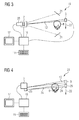
- Figure 1 shows a apparatus 1 for panoramic dental radiography that comprises a X-ray tube 2 and an X-ray detector 3 for detecting the radiation crossing the body of the patient 4.
- the detector 3 may be a digital X-ray detector 3 that comprises a matrix of sensible elements or so called pixels, often covered by X-ray detecting scintillator material.
- Linear shaped area detectors provide the most economic solution to realize a digital radiographic apparatus. For instance, they are widely used to build orthopantomographs aimed to dental radiography. In this case, both the detector 3 and the tube 2 perform a trajectory in the three-dimensional space focusing on a specific target surface 5, for instance the dental arch of the patient 4.
- the tube 2 and the detector 3 are attached to a support structure 6 that can be rotated around a vertical rotation axis 7 aligned onto a head 8 of the patient 4.
- a fixing unit 9 is provided with the apparatus 1.
- the fixing unit comprises a bite block that the patient 4 can introduce into the mouth. While the patient 4 bites on the bite block the dental arch of the patient 4 is kept stationary during the image acquisition process.
- Image quality is fundamental to achieve the best clinical results in digital radiography.
- several acquisition parameters for instance the X-ray exposure profile or the position of important anatomical structures, have to be set taking in consideration the actual anatomy of the patient 4.
- these parameters are set by the operator either manually or following some golden rule, which may not lead to optimized results for the specific patient 4.
- the operator In dental radiography, the operator has to accomplish various critical tasks, which may highly affect the diagnostic value of any acquired radiography. Among others, these tasks are the positioning of the patient 4, the identification of the size of the patient 4, the identification of reference anatomical points, the selection of the anatomical region of interest, the control of the stability of the patient during X-ray exposure, as well as the recognition of the patient's identity.
- the operator may set operational parameters of the radiographic apparatus, which may lead to an inadequate diagnostic image. Estimating the size of the patient 4 also constitutes a time consuming procedure.
- the modulation of exposure is a general problem in radiography, as the dose should be adapted to the local tissue crossed by the beam, so that the detector receives enough signal, avoiding at the same time the delivery of an excessive dose to specific anatomical structures.
- the X-ray dose is generally increased in correspondence to the spine, to obtain a uniform exposure; the modulation is performed according to a predefined exposure pattern, which is not necessarily optimal for any patient 4.
- the spine position may be shifted with respect to its reference position resulting in images of low quality, if the displacement is not compensated.
- a typical artifact is represented by a series of stripes appearing in the image.
- the apparatus 1 for dental radiography is equipped with a biometric system, which automates various procedures which have to be carried out before radiographic acquisition, with the aim of optimizing the image quality.
- the biometric system may include an artificial vision system and may additionally comprise several sensors or three-dimensional scanners, which provide a multiplicity of biometrical data including lengths, areas, volumes, weights and morphological data such as two-dimensional views and three-dimensional models which can be processed for obtaining biometric data, in particular specific morphological parameters.
- FIG 1 only a single video camera 10 is shown.
- the artificial vision system can also be based on a set of one or more two-dimensional cameras, fixed or moving around the patient 4. In the latter case the cameras could be mounted on the common support structure 6 for the X-ray tube 2 and the detector 3.
- Such an apparatus can provide a set of two-dimensional images or reconstruct the three-dimensional surface of the head 8 of the patient 4.
- the apparatus can be particularly arranged for determining the body height of the patient 4 by measuring the height of the fixing unit 9 since the height of the fixing unit 9 above floor depends on the body height of the patient 4.
- Figure 2 shows a schematic view from above on an apparatus 11 for narrow-beam tomography by a narrow X-ray radiation beam 12.
- the tube 2 and the detector 3 of apparatus 11 are equipped with cameras 13 and 14 mounted onto the tube 2 and the detector 3. Both cameras 13 and 14 can be used to locate the position of the spine of the patient 4 and the position and the profile of the dental arch.
- Both cameras 13 and 14 can be used to locate the position of the spine of the patient 4 and the position and the profile of the dental arch.
- the specific anatomy of the patient 4 can be taken into account while moving the tube 2 and the detector 3 on a trajectory 15 for taking tomographic images of the dentition of the patient 4.
- the cameras 13 and 14 are connected to a processing unit 16 which is also provided with a display unit 17 and input devices 18, such as a keyboard.
- the processing unit 16 is also connected with the tube 2, the detector 3 and a drive system for moving the tube 2 and the detector 3 on the trajectory 15.
- Figure 3 shows another apparatus 19 for cephalometric imaging.
- the beam 12 has the shape of a fan located in a vertical plan.
- the apparatus 19 is further provided with a stationary video camera 20 that is disposed next to the tube 2.
- additional mirrors 21 are provided, so that the camera 20 is able to record views of the head 8 from three sides, namely a front side view, a back side view and a lateral view. From the views the anatomy of the head 8 of the patient 4 can derived and the operational parameters of the imaging process gradually adjusted to the anatomy of the cranial region actually crossed by the beam 12 while the detector 3 and the beam 12 are moving in a direction 22.
- a good visualization of both soft and hard tissues is particularly advantageous.
- the cameras 10, 13, 14 or 20 can be video cameras or photo cameras.
- Figure 4 depicts an apparatus 23, which is also used for cephalometric imaging.
- the X-ray beam 12 generally has the shape of a fan located in a vertical plan.
- the light beam 24 is generated by a light source 25 located next to the tube 2 and detected by a photodetector 26, which preferably comprises an linear array of detector elements.
- the photodetector 26 moves together in the direction 22.
- the photodetector 26 is fully illuminated, but is only partially illuminated when the photodetector becomes obscured by the head 8 of the patient 4.
- the silhouette such acquired can be used for adjusting the exposure of the soft tissue of the patient 4.
- the various apparatus 1, 11, 19 and 23 are shortly referred to as the apparatus. Furthermore, by referring to the set of cameras we refer to any one of the cameras 10, 13, 14 and 20 or the photo detector 26.
- a sensor 27 is used for retrieving morphological raw data relating to the anatomy of the patient 4. If any camera of the set of cameras is used as sensor 27, the morphological raw data will be images of the patient 4 taken by the camera.
- anatomical features are identified based on the morphological raw data. These anatomical features can be the contour of a face of the patient 4 or other anatomical landmarks such as the eye, the ears, the nose or the mouth of the patient 4. Therefore, a search for the anatomical features is performed during the data processing 28.
- biometric data are derived from the morphological raw data by further processing 29.
- the further processing 29 results in biometric data such as spatial coordinates of the anatomical features.
- the processing 29 may result in the position of a central point of the eyes or the position of the nasion with respect to the coordinate system or may also result in absolute biometric data such as the width of the head 8 measured between the ears of the patient.
- operational parameters are obtained by processing 30 the biometric data.
- the operational parameter are finally used for an imaging process 31. During the imaging process the radiographic images of the patient are taken.
- the sensor 27 is acquiring the morphological raw data in a contactless way. It should be noted, however, that the raw data may also include data which are acquired in contact with the patient. Accordingly an additional sensor 32 may be provided with the apparatus 1, 11, 19 and 23 for the acquisition of additional raw data in contact with the patient 4. These additional raw data may particularly be data which relate to the movement of the patient 4 during the acquisition of the morphological raw data by the sensor 27.
- the sensor 32 can be a speed sensor or an accelerometer
- biometric data directly supplied by a sensor 33 can be used for the processing 28 and the processing 30. These data can be a length, height or weight measured by suitable sensing devices in contact with the patient 4. These direct biometric data can be used among other purposes for calibration purposes or for consistency checks.
- any camera of the set of cameras can be used to automatically estimate the size of the patient 4 and consequently the operational parameters which optimize the acquisition process of the radiographic apparatus.
- the set of cameras may further be used to automatically recognize the identity of a patient 4, to provide color images, which can be used by the operator to select a particular region of interest and to estimate the shape and the size of the dental arch of the patient 4.
- the data acquisition of the morphological raw data can be replaced or integrated with other biometrical data from local anatomical measurements, like for instance, the measurement of the wrist width, patient height and weight and temple width.
- Pattern recognition techniques process these anatomical data to compute the position of several anatomical features of the head 8, which are used to optimize the process of the radiographic acquisition.
- the most refined pattern analysis approaches are based on statistical analysis and a combination of the previously introduced techniques: for instance, they permit to reliably recognize a face among a dataset of face images through the analysis of the facial features.
- basic pattern analysis approaches are used to individuate a single feature of the face, for instance an eye or a mouth.
- the basic approaches can be used to individuate the features; the correct constellation of the features is then selected between the candidate constellations, using some statistical criteria. For instance, there is a null probability for the mouth to lie over the eyes.
- a statistical approach based on constellation is more reliable than a simple set of basic approaches for single feature identification.
- the apparatus uses biometric data, for instance the structure of anatomical surfaces or fingerprints, to identify the identity of the patient 4.
- the identification of the patient 4 can be based on biometric data derived from different sensors. Independently from the kind of sensors used, the data of the patient 4 have to be kept stored in a database. Therefore, a procedure is preferably implemented to record these data, when the patient 4 approaches the apparatus for the first time. Security procedures are adopted to ensure adequate storage and retrieval of patient data to avoid mix up and confusion.
- Typical patient data include personal data as well as radiographic images and intra oral and extra oral pictures taken with a general purpose or dental camera.
- the apparatus is equipped with a set of cameras, which capture the face of the patient 4. Any known algorithms can be used to individualize the identity of the patient 4 from the optical images.
- the apparatus is also equipped with a three-dimensional scanner.
- three-dimensional data can be used to increase the reliability of the patient recognition system, as specific morphological measurements are available.
- the apparatus may be equipped with a fingerprint sensor or a voice sensor or an iris recognition sensor. Each of these sensor provide sufficient data to identify the patient 4. Other biometric surveying systems can be used as well.
- a particular advantage of the first method is that it provides the opportunity of an automated verification of the patient identity.
- a second method relates to the automatic identification of the size of the patient 4 and the computation of the corresponding operational parameters for the acquisition of an X-ray image.
- the apparatus uses multiple anatomical data of the patient 4 to identify the size of the patient 4 and preferred associated operational parameters for the X-ray imaging process.
- the method uses several anatomical parameters, as for instance a facial contour, a facial area, as well as the height or weight of the patient 4 to compute and provide as output a classification of the size and/or bone thickness of the head 8 of the patient 4. These values might be used by the clinician or also automatically used by the system to set up the operational parameters of the imaging process.
- a particular advantage of the second method is that it provides a quantitative evaluation of the size of the patient 4 and the associated operational parameters independent of the skills and the actual state of fatigue of the operator.
- a panoramic radiography is acquired.
- the patient 4 has to be accurately positioned inside the apparatus by the clinical operator.
- the used apparatus might be similar to the apparatus 1 depicted in Figure 1 .
- the positioning of the patient 4 may require that the patient 4 bites on a bite block of the fixing unit 9 or presses his head against any other head resting constraint.
- the face of the patient 4 is surveyed by the camera 10 positioned in front of the face of the patient 4, as shown in Figure 1 .
- the patient 4 Since the patient 4 is positioned in a standard position, its distance d from the optical focus of the camera 10 is constant, independently from the actual patient 4; as a consequence, also the magnification factor of the camera 10 surveying the face of the patient 4 does not depend on the patient 4.
- the frontal image of the patient 4 can be processed by a processing unit similar to the processing unit depicted in Figure 2 and 3 to estimate the anatomical parameters of the face of the patient 4, in particular the size of the face of the patient 4.
- Background subtraction is one of the possibilities which can be employed to determine the contours of the face: an image without any patient 4 is taken first. This image constitutes the background image. Once the patient 4 has been positioned in place, another image is taken and subtracted to the background image. The difference image contains the outline of the patient 4, which provides an estimate of its size. However, due to shadows, this image is often irregular. Moreover, certain types of hair styles, do not allow estimating the true shape of the forehead and of the head 8. One possibility is therefore to consider only the lower part of the face and to regularize the difference image as in GOTO et al.
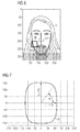
- the shape of the face can also be represented, for instance, by a hyperellipse 37 as depicted in Figure 7 .
- a chin region 35 may not be visible. Instead, the alternative approach operates directly on the acquired raw image.
- the gradient of the raw image is computed to enhance the face outline as in GOTO et al. and the shape of the face is then fitted through an adequate curve model. From the parameters of the fitted curve and the magnification factor, the size of the face of the patient 4 is then estimated.
- Another approach for estimating the anatomical parameters and in particular the size of the head 8 is based on a three-dimensional surface image of the face obtained by three-dimensional scanners or cameras. Fitting a parametric three-dimensional model of the face onto the acquired data allows deriving the size.
- image processing methods for deriving the face shape can be used as well. It might, for instance, be useful to take image in the infrared wavelength range for identifying the outlines of the face by the temperature difference between the skin and the hair.
- the operation parameters for the imaging process by the radiographic apparatus can be derived, following some specific optimization criteria.
- AEC automatic exposure control
- a third method for using the sensing capabilities of the apparatus is directed towards a method for utilizing a multiplicity of two-dimensional image views or three-dimensional images or curvilinear surfaces to identify the profile of the true dental arch of the patient 4.
- the shape of the dental arch of the patient 4 can be computed.
- an adequate statistical model for instance a morphable model as disclosed in BLANZ and VETTER, can be adopted to relate the face shape measured on the image with the shape of the dental arch.
- the apparatus and the methods also provide a correct positioning of the patient 4 avoiding the errors which occur at the operation of panoramic X-ray equipments, in particular the errors associated with methods to identify the actual protrusion of the incisors and correct the positioning of the patient 4 accordingly or associated with methods for positioning of the theoretic target dental arch profile, following a subjective evaluation of the operator supported by light indicators or the like.
- the apparatus and the method allow an automatic correction of the positioning errors caused by the inclination of the incisors and the deviation between the labial end of the incisors determining the position of the incisors in the bite unit and the root of the incisors which determines the position of the dental arch profile.
- ROI region of interest 36
- the apparatus will be instructed by the clinical operator to modulate the X-ray exposure inside the region of interest 36, for instance increasing or decreasing the dose inside the region of interest 36 with respect to the outside.
- SNR signal-to-noise ratio
- the region of interest 36 can be identified by the operator, by various standard means, like, for instance, selecting a rectangular window over the displayed image. Since the apparatus is equipped with a set of cameras, the images taken by the set of cameras are used to identify a window, the region of interest 36, corresponding to an area with special properties.
- the region of interest 36 can, for instance, correspond to the local volume required for radiography or tomography or can be an area which has to be spared from radiation or an area which requires a higher dose.
- the region of interest 36 can also be identified on the rotated image or through the following procedure: A morphable face model is created as in BLANZ and VETTER, which is fitted to the actual face image. This model is then rotated automatically by software until it assumes the optimal orientation for setting the region of interest 36.
- the model can be automatically rotated until it assumes the optimal orientation to set the region of interest 36.
- face features can be automatically superimposed on the video image.
- these features can be a schematic representation of the dentition.
- two-dimensional image views, three-dimensional volume images or three-dimensional curvilinear surface images of the head 8 are used to obtain a picture of the head 8 to automatically identify anatomical districts which require different exposures.
- anatomical districts are the transition region between soft and bony tissue in lateral cephalography and the region of the cervical spine in panoramic radiography or local tomography.
- this information is used to decrease the dose in the frontal part of the head 8, where soft tissue is present. Thus the radiation exposure in the soft tissue regions can be reduced or eliminated.
- the position of the cervical spine vary the X-ray modulation profile such that a uniform exposure is achieved on the entire image. If necessary, the sensitivity of the detector 3 can also be adjusted to the dose.
- this kind of information is used to optimize the modulation of the X-ray exposure profile, so that any unnecessary radiation exposure is avoided in particular for both soft and bony tissue and also for other anatomical structures that must be preserved from high dose irradiation.
- a particular advantage of the apparatus operated according to the fifth method is that it provides an automated identification of specific anatomical districts such as the spine in panoramic radiography or the transition from soft to bony tissue in cephalography, where a modulation of the operational parameter of the radiation exposure is automatically performed, without requiring intervention or subjective evaluations by the operator.
- a two-dimensional or three-dimensional view of the head 8 is used to automatically identify the morphology of the patient 4 and to modulate the intensity of the radiation emitted by the X-ray tube accordingly.
- a frontal camera is mounted in an apparatus for panoramic radiography.
- an apparatus can be an apparatus similar to the apparatus 11 shown in Figure 2 .
- the position and size of the cervical spine can be identified by analyzing the patient images.
- the position of the spine can be identified by image processing techniques arranged for identifying the spine pattern directly and/or in relation with other anatomical structures like eyes, nose, and chin.
- the spine position can be used to modulate the X-ray exposure profile to compensate for higher absorption by the spine.
- Another embodiment of the fifth method relates to cephalography.
- an apparatus as the apparatus 19 shown in Figure 3 might be used.
- a lateral image of the patient 4 is taken by the lateral camera 20.
- an adaptive parametric curve can automatically be fitted to the lateral profile of the patient 4. This can be carried out, for instance, by searching for a parametric curve which maximizes the norm of the gradient along the curve itself. From this curve a set of reference points, like for instance the nasion, can be automatically derived and used to automatically optimize the X-ray exposure, modulating the X-ray intensity during the acquisition such that both the soft and bony tissue are correctly exposed.
- Exposure profiles in terms of KV or mA for the voltage and the current of the tube 2 can automatically be set according to different criteria such as maximization of the contrast, maximization of SNR or minimization of the dose applied to the patient 4.
- the sixth method is directed to a method in which the processing of the acquired radiographic image produces as an output a synthesized lateral view of the skull of the patient 4 with an overlay of the radiographic images and camera views supporting the identification of the morphological landmarks of the patient 4 with particular regard to soft tissues of the head 8.
- two-dimensional image views or two-dimensional projections of three-dimensional surface images are superimposed over a two-dimensional radiographic image, to obtain a single image containing both the radiographic view and the video image with the visible anatomy in particular at the surface of the patient 4.
- the synthesized image is preferably obtained by utilizing the processing techniques used for image registration in artificial vision.
- the synthesized image can help the operator to identify the patient morphological landmarks with particular regard to the soft tissues of the head 8, for instance nose, lips, chin.
- an accurate registration algorithm is needed to perform a reliable matching between the radiographic and image data.
- the sixth method is preferably based on a lateral or frontal image of the head 8, or a combination thereof.
- the method uses the video image and the X-ray image, registered in space through an adequate and accurate calibration procedure.
- the method provides a single output image blending the two images as in WHITAKER. To increase the diagnostic significance of the images, the blending coefficient could be set to obtain the maximum visibility of the anatomical structures through an adequate algorithm.
- Blending coefficients can be set automatically to a different value in different regions, according to local contrast evaluation, obtaining therefore a blending field. Blending coefficients can be obtained for instance by maximizing the visibility of both soft and bony tissues in X-ray images as in WHITAKER or in FROSIO, FERRIGNO and BORGHESE.
- Three-dimensional images can be used alternatively to two-dimensional images.
- the three-dimensional image can be projected over the X-ray image at an arbitrary orientation.
- Another embodiment of the present invention is directed to analyze the effect which has the modification of the bone structure, following maxillo-facial or plastic surgery, on the soft tissue and, in turn, on the face aspect.
- the mixed image can be locally stretched coherently with the anatomical modifications introduced by the surgery to highlight the effect of the surgery onto the anatomy of the patient 4.
- a particular advantage of the sixth method is the possibility to process and combine the information of the radiographic views and the camera views in order to obtain a synthesized image that can be used by the operator to identify the morphological landmarks of the patient 4 with particular regard to the soft tissues of the head 8, in particular nose, lips and chin.
Landscapes
- Health & Medical Sciences (AREA)
- Life Sciences & Earth Sciences (AREA)
- Engineering & Computer Science (AREA)
- Medical Informatics (AREA)
- Physics & Mathematics (AREA)
- General Health & Medical Sciences (AREA)
- Veterinary Medicine (AREA)
- Molecular Biology (AREA)
- Public Health (AREA)
- Animal Behavior & Ethology (AREA)
- Surgery (AREA)
- Heart & Thoracic Surgery (AREA)
- Biophysics (AREA)
- Pathology (AREA)
- Biomedical Technology (AREA)
- Radiology & Medical Imaging (AREA)
- Nuclear Medicine, Radiotherapy & Molecular Imaging (AREA)
- Optics & Photonics (AREA)
- Oral & Maxillofacial Surgery (AREA)
- High Energy & Nuclear Physics (AREA)
- Dentistry (AREA)
- Multimedia (AREA)
- General Physics & Mathematics (AREA)
- Theoretical Computer Science (AREA)
- Human Computer Interaction (AREA)
- Neurology (AREA)
- Neurosurgery (AREA)
- Apparatus For Radiation Diagnosis (AREA)
Priority Applications (3)
| Application Number | Priority Date | Filing Date | Title |
|---|---|---|---|
| EP08157813.0A EP2130491B1 (fr) | 2008-06-06 | 2008-06-06 | Procédé et appareil pour imagerie radiographique |
| US12/479,254 US7929661B2 (en) | 2008-06-06 | 2009-06-05 | Method and apparatus for radiographic imaging |
| US13/088,192 US8223915B2 (en) | 2008-06-06 | 2011-04-15 | Method and apparatus for radiographic imaging |
Applications Claiming Priority (1)
| Application Number | Priority Date | Filing Date | Title |
|---|---|---|---|
| EP08157813.0A EP2130491B1 (fr) | 2008-06-06 | 2008-06-06 | Procédé et appareil pour imagerie radiographique |
Publications (2)
| Publication Number | Publication Date |
|---|---|
| EP2130491A1 true EP2130491A1 (fr) | 2009-12-09 |
| EP2130491B1 EP2130491B1 (fr) | 2015-08-05 |
Family
ID=39817861
Family Applications (1)
| Application Number | Title | Priority Date | Filing Date |
|---|---|---|---|
| EP08157813.0A Active EP2130491B1 (fr) | 2008-06-06 | 2008-06-06 | Procédé et appareil pour imagerie radiographique |
Country Status (2)
| Country | Link |
|---|---|
| US (2) | US7929661B2 (fr) |
| EP (1) | EP2130491B1 (fr) |
Cited By (12)
| Publication number | Priority date | Publication date | Assignee | Title |
|---|---|---|---|---|
| NL2008400A (en) * | 2011-03-03 | 2012-09-04 | Gen Electric | Method to reduce radiation dose delivered by imaging system. |
| WO2013021231A1 (fr) * | 2011-08-05 | 2013-02-14 | Trophy | Détection de hauteur de colonne pour imagerie extra-orale |
| EP2531109A4 (fr) * | 2010-02-02 | 2013-10-09 | Planmeca Oy | Appareil d'imagerie dentaire |
| CN103654809A (zh) * | 2012-08-31 | 2014-03-26 | 西门子公司 | 用于自动定位x射线设备的拍摄系统的方法和x射线设备 |
| WO2015007710A1 (fr) * | 2013-07-15 | 2015-01-22 | Sirona Dental Systems Gmbh | Procédé pour la production d'une radiographie |
| WO2018122451A1 (fr) | 2016-12-30 | 2018-07-05 | Planmeca Oy | Tomographie assistée par ordinateur et positionnement de l'anatomie à imager |
| WO2018167375A1 (fr) * | 2017-03-17 | 2018-09-20 | Planmeca Oy | Tomodensitométrie et positionnement d'un volume à imager |
| CN110063741A (zh) * | 2018-01-24 | 2019-07-30 | 帕洛代克斯集团有限公司 | 用于x射线成像的x射线成像单元 |
| EP3582227A1 (fr) * | 2018-06-15 | 2019-12-18 | Siemens Healthcare GmbH | Procédé de fonctionnement d'un dispositif d'acquisition d'images médicales, dispositif d'acquisition d'images, programme informatique et support d'informations lisible électroniquement |
| CN112822983A (zh) * | 2018-11-07 | 2021-05-18 | 登士柏希罗纳有限公司 | 用于编辑全景射线照相图像的设备和方法 |
| EP4198903A1 (fr) * | 2021-12-17 | 2023-06-21 | DENTSPLY SIRONA Inc. | Images tomographiques panoramiques |
| US12329559B2 (en) | 2019-09-03 | 2025-06-17 | Koninklijke Philips N.V. | X-ray imaging system |
Families Citing this family (38)
| Publication number | Priority date | Publication date | Assignee | Title |
|---|---|---|---|---|
| WO2007143831A1 (fr) * | 2006-06-12 | 2007-12-21 | Trefford Simpson | Procédé d'étalonnage de dispositif biométrique |
| EP2521095B1 (fr) * | 2008-07-14 | 2015-03-04 | Cefla S.C. | Correction d'erreur dynamique en imagerie radiographique |
| DE102008035412A1 (de) * | 2008-07-29 | 2010-02-04 | Sirona Dental Systems Gmbh | Verfahren zur Erstellung einer dentalen 3D-Röntgenaufnahme und Röntgengerät hierfür |
| KR101094180B1 (ko) * | 2009-11-10 | 2011-12-14 | 주식회사바텍 | 파노라마 영상 획득 방법 및 장치 |
| US8430563B2 (en) * | 2009-12-22 | 2013-04-30 | Real Time Imaging Technologies, Llc | Dental fluoroscopic imaging system |
| US9579073B2 (en) * | 2010-05-07 | 2017-02-28 | Apteryx, Inc. | System and method for dentition specific image enhancement |
| US8861679B2 (en) | 2010-06-11 | 2014-10-14 | Palodex Group Oy | X-ray imaging systems and methods |
| US8705695B2 (en) * | 2010-11-23 | 2014-04-22 | General Electric Company | Region of interest determination for X-ray imaging |
| US8266742B2 (en) | 2010-12-06 | 2012-09-18 | Hill-Rom Services, Inc. | Biometric bed configuration |
| KR101175027B1 (ko) * | 2011-02-25 | 2012-08-17 | 이화여자대학교 산학협력단 | 카메라가 구비된 구강 내 엑스선 촬영장치 |
| US8744162B2 (en) * | 2011-03-25 | 2014-06-03 | Midmark Corporation | Image evaluation method and system |
| KR20130068396A (ko) * | 2011-12-15 | 2013-06-26 | 삼성전자주식회사 | 디지털디텍터 및 이를 이용한 방사선장치 |
| US9700247B2 (en) | 2012-03-21 | 2017-07-11 | Hill-Rom Services, Inc. | Patient support apparatus with redundant identity verification |
| KR101527812B1 (ko) * | 2012-11-06 | 2015-06-10 | 삼성전자 주식회사 | 방사선 영상촬영장치 및 그 제어방법 |
| US9609290B2 (en) * | 2013-07-10 | 2017-03-28 | Subc Control Limited | Telepresence method and system for supporting out of range motion by aligning remote camera with user's head |
| US9005101B1 (en) | 2014-01-04 | 2015-04-14 | Julian Van Erlach | Smart surface biological sensor and therapy administration |
| US20170258420A1 (en) * | 2014-05-22 | 2017-09-14 | Carestream Health, Inc. | Method for 3-D Cephalometric Analysis |
| US10617373B2 (en) * | 2014-11-12 | 2020-04-14 | Vatech Co., Ltd. | Dental X-ray radiographing apparatus having radiographing unit housing |
| DE102014223802A1 (de) * | 2014-11-21 | 2016-05-25 | Sirona Dental Systems Gmbh | Verfahren und Vorrichtung zur Bereitstellung von zwei digitalen Panoramaschichtbildern |
| EP3244800A1 (fr) | 2015-01-12 | 2017-11-22 | Real Time Imaging Technologies, LLC | Système d'imagerie radiographique à faible dose |
| DE102015202999B4 (de) * | 2015-02-19 | 2019-12-05 | Siemens Healthcare Gmbh | Automatisierte Justierung von Signalanalyseparametern für Röntgendetektoren |
| WO2016135526A1 (fr) * | 2015-02-27 | 2016-09-01 | Trophy | Bloc d'occlusion pour dispositif d'imagerie cbct |
| DE102015204449A1 (de) * | 2015-03-12 | 2016-09-15 | Siemens Healthcare Gmbh | Verfahren zum Bestimmen eines Röntgenröhrenstromprofils, Computerprogramm, Datenträger sowie Röntgenbildaufnahmevorrichtung |
| WO2016156150A1 (fr) * | 2015-03-27 | 2016-10-06 | 3Shape A/S | Procédé de réduction de dose de rayons x dans un système à rayons x |
| KR20170007181A (ko) | 2015-07-10 | 2017-01-18 | 3스캔 인크. | 조직학적 염색제의 공간 다중화 |
| WO2017076841A1 (fr) | 2015-11-04 | 2017-05-11 | Koninklijke Philips N.V. | Dispositif pour l'imagerie d'un objet |
| DE102017004705A1 (de) | 2017-05-16 | 2018-11-22 | Ziehm Imaging Gmbh | Verfahren zum Erzeugen eines in der Zentralschicht vollständigen 3D-Datensatzes zur Volumenrekonstruktion und Röntgensystem mit einem Kegelstrahl-C-Bogen-Röntgengerät zur Durchführung des Verfahrens |
| DE202017002625U1 (de) | 2017-05-16 | 2017-05-29 | Ziehm Imaging Gmbh | Röntgensystem mit einem Kegelstrahl-C-Bogen-Röntgengerät zum Erzeugen eines in der Zentralschicht vollständigen 3D-Datensatzes zur Volumenrekonstruktion |
| CN108403134A (zh) * | 2018-01-29 | 2018-08-17 | 北京朗视仪器有限公司 | 基于口腔ct设备进行人脸3d扫描的方法和装置 |
| WO2019204520A1 (fr) * | 2018-04-17 | 2019-10-24 | VideaHealth, Inc. | Détection de caractéristique d'image dentaire |
| US11450151B2 (en) * | 2019-07-18 | 2022-09-20 | Capital One Services, Llc | Detecting attempts to defeat facial recognition |
| US11284847B2 (en) | 2020-06-30 | 2022-03-29 | GE Precision Healthcare LLC | X-ray imaging system and method |
| JPWO2022054875A1 (fr) * | 2020-09-09 | 2022-03-17 | ||
| WO2022064845A1 (fr) * | 2020-09-25 | 2022-03-31 | 富士フイルム株式会社 | Dispositif de réglage, procédé de réglage et programme de réglage |
| FI130129B (en) * | 2020-10-28 | 2023-03-09 | Palodex Group Oy | Controls, dental imaging system, and method for dental imaging of an object |
| US11779289B2 (en) * | 2020-11-03 | 2023-10-10 | Palodex Group Oy | Two-way mirror display for dental treatment system |
| CN114748085B (zh) * | 2022-04-22 | 2023-01-10 | 南方医科大学南方医院 | 一种基于运动识别的x线曝光方法、系统及装置 |
| FI20225840A1 (en) * | 2022-09-27 | 2024-03-28 | Palodex Group Oy | Dental X-ray imaging system and method for dental X-ray imaging of a patient |
Citations (21)
| Publication number | Priority date | Publication date | Assignee | Title |
|---|---|---|---|---|
| DE3632878A1 (de) | 1986-09-26 | 1988-03-31 | Siemens Ag | Vorrichtung zur positionierung des kopfes eines patienten zur anfertigung einer roentgenaufnahme |
| US4856038A (en) | 1986-09-26 | 1989-08-08 | Siemens Aktiengesellschaft | Dental x-ray diagnostics installation for producing panoramic exposures of slices in the skull |
| US4907251A (en) * | 1987-03-13 | 1990-03-06 | Kabushiki Kaisha Morita Seisakusho | Patient positioning device in medical panorama X-ray photographing apparatus |
| US5425065A (en) | 1991-08-19 | 1995-06-13 | Instrumentarium Corp.- Imaging Division | Automatic exposure apparatus for panoramic x-ray equipment |
| US6081739A (en) * | 1998-05-21 | 2000-06-27 | Lemchen; Marc S. | Scanning device or methodology to produce an image incorporating correlated superficial, three dimensional surface and x-ray images and measurements of an object |
| JP2001346796A (ja) | 2000-06-07 | 2001-12-18 | Yoshida Dental Mfg Co Ltd | パノラマx線撮影位置づけ自動調整装置 |
| EP1216661A2 (fr) * | 2000-12-18 | 2002-06-26 | GE Medical Systems Global Technology Company LLC | Procédé et appareil de diagnostic médical pour le contrôle de techniques d'exposition à deux spectres d'énergie basées sur des informations d'images |
| US20020085672A1 (en) * | 2000-12-28 | 2002-07-04 | Alexander Ganin | Automatic exposure control and optimization in digital x-ray radiography |
| US20030007602A1 (en) * | 2001-06-22 | 2003-01-09 | J. Morita Manufacturing Corporation | Scan type digital X-ray imaging apparatus |
| US6510196B2 (en) | 2000-06-02 | 2003-01-21 | Instrumentarium Corporation | Determination and adjustment of exposure values for X-ray imaging |
| WO2003010555A2 (fr) * | 2001-07-24 | 2003-02-06 | Case Western Reserve University | Regulation de la dose de rayons x en fonction de la taille du patient |
| US6614875B2 (en) | 2000-10-11 | 2003-09-02 | Instrumentarium Corp. | Method and apparatus for imaging the head area of a patient |
| US20040096035A1 (en) | 2002-11-15 | 2004-05-20 | Canon Kabushiki Kaisha | X-ray imaging apparatus |
| US20050031080A1 (en) * | 2003-07-22 | 2005-02-10 | Klaus Klingenbeck-Regn | X-ray diagnostic apparatus with a body mass index calculator for controlling x-ray emissions |
| EP1624411A2 (fr) | 2004-08-06 | 2006-02-08 | Gendex Corporation | Filtrage de tissus mous dans des images médicales |
| DE102004042790A1 (de) * | 2004-09-03 | 2006-03-09 | Siemens Ag | Röntgeneinrichtung |
| US20060213996A1 (en) * | 2005-03-23 | 2006-09-28 | Apteryx, Inc. | System and method to adjust medical imaging equipment |
| US7133496B2 (en) | 2004-03-09 | 2006-11-07 | David G. Wilson, D.M.D., Llc | Soft tissue cephalometric screen with submental-neck extension, and radiology apparatus, modular system and imaging method using same |
| EP1772101A1 (fr) * | 2005-10-06 | 2007-04-11 | Fujifilm Corporation | Appareil pour mammographie |
| US20070172102A1 (en) * | 2006-01-13 | 2007-07-26 | Eckhard Hempel | Imaging apparatus and method for the operation thereof |
| US20070183567A1 (en) | 2006-02-01 | 2007-08-09 | Gendex Corporation | Dental x-ray apparatus and method of positioning a patient therein |
Family Cites Families (1)
| Publication number | Priority date | Publication date | Assignee | Title |
|---|---|---|---|---|
| US7894664B2 (en) * | 2006-03-22 | 2011-02-22 | University Of Washington | Conditional shape model for image processing |
-
2008
- 2008-06-06 EP EP08157813.0A patent/EP2130491B1/fr active Active
-
2009
- 2009-06-05 US US12/479,254 patent/US7929661B2/en active Active
-
2011
- 2011-04-15 US US13/088,192 patent/US8223915B2/en active Active
Patent Citations (22)
| Publication number | Priority date | Publication date | Assignee | Title |
|---|---|---|---|---|
| US4856038A (en) | 1986-09-26 | 1989-08-08 | Siemens Aktiengesellschaft | Dental x-ray diagnostics installation for producing panoramic exposures of slices in the skull |
| DE3632878A1 (de) | 1986-09-26 | 1988-03-31 | Siemens Ag | Vorrichtung zur positionierung des kopfes eines patienten zur anfertigung einer roentgenaufnahme |
| US4907251A (en) * | 1987-03-13 | 1990-03-06 | Kabushiki Kaisha Morita Seisakusho | Patient positioning device in medical panorama X-ray photographing apparatus |
| US5425065A (en) | 1991-08-19 | 1995-06-13 | Instrumentarium Corp.- Imaging Division | Automatic exposure apparatus for panoramic x-ray equipment |
| US6081739A (en) * | 1998-05-21 | 2000-06-27 | Lemchen; Marc S. | Scanning device or methodology to produce an image incorporating correlated superficial, three dimensional surface and x-ray images and measurements of an object |
| US6510196B2 (en) | 2000-06-02 | 2003-01-21 | Instrumentarium Corporation | Determination and adjustment of exposure values for X-ray imaging |
| JP2001346796A (ja) | 2000-06-07 | 2001-12-18 | Yoshida Dental Mfg Co Ltd | パノラマx線撮影位置づけ自動調整装置 |
| US6614875B2 (en) | 2000-10-11 | 2003-09-02 | Instrumentarium Corp. | Method and apparatus for imaging the head area of a patient |
| EP1216661A2 (fr) * | 2000-12-18 | 2002-06-26 | GE Medical Systems Global Technology Company LLC | Procédé et appareil de diagnostic médical pour le contrôle de techniques d'exposition à deux spectres d'énergie basées sur des informations d'images |
| US20020085672A1 (en) * | 2000-12-28 | 2002-07-04 | Alexander Ganin | Automatic exposure control and optimization in digital x-ray radiography |
| US7103141B2 (en) | 2001-06-22 | 2006-09-05 | J. Morita Manufacturing Corporation | Scan type digital X-ray imaging apparatus |
| US20030007602A1 (en) * | 2001-06-22 | 2003-01-09 | J. Morita Manufacturing Corporation | Scan type digital X-ray imaging apparatus |
| WO2003010555A2 (fr) * | 2001-07-24 | 2003-02-06 | Case Western Reserve University | Regulation de la dose de rayons x en fonction de la taille du patient |
| US20040096035A1 (en) | 2002-11-15 | 2004-05-20 | Canon Kabushiki Kaisha | X-ray imaging apparatus |
| US20050031080A1 (en) * | 2003-07-22 | 2005-02-10 | Klaus Klingenbeck-Regn | X-ray diagnostic apparatus with a body mass index calculator for controlling x-ray emissions |
| US7133496B2 (en) | 2004-03-09 | 2006-11-07 | David G. Wilson, D.M.D., Llc | Soft tissue cephalometric screen with submental-neck extension, and radiology apparatus, modular system and imaging method using same |
| EP1624411A2 (fr) | 2004-08-06 | 2006-02-08 | Gendex Corporation | Filtrage de tissus mous dans des images médicales |
| DE102004042790A1 (de) * | 2004-09-03 | 2006-03-09 | Siemens Ag | Röntgeneinrichtung |
| US20060213996A1 (en) * | 2005-03-23 | 2006-09-28 | Apteryx, Inc. | System and method to adjust medical imaging equipment |
| EP1772101A1 (fr) * | 2005-10-06 | 2007-04-11 | Fujifilm Corporation | Appareil pour mammographie |
| US20070172102A1 (en) * | 2006-01-13 | 2007-07-26 | Eckhard Hempel | Imaging apparatus and method for the operation thereof |
| US20070183567A1 (en) | 2006-02-01 | 2007-08-09 | Gendex Corporation | Dental x-ray apparatus and method of positioning a patient therein |
Non-Patent Citations (14)
| Title |
|---|
| BLANZ, V.; VETTER, T.: "A Morphable Model for the Synthesis of 3D Faces", SIGGRAPH 99 CONFERENCE PROCEEDINGS |
| BLANZ, V.; VETTER, T.: "Face Recognition Based on Fitting a 3D Morphable Model", IEEE TRANSACTIONS ON PATTERN ANALYSIS AND MACHINE INTELLIGENCE, vol. 25, no. 9, 2003, pages 1063 - 1074, XP011100733, DOI: doi:10.1109/TPAMI.2003.1227983 |
| ELBAKRI, I. ET AL.: "Automatic Exposure control for a slot scanning full field digital mammography systems", MED. PHYS., vol. 32, 2005, pages 2763 - 2770, XP012075447, DOI: doi:10.1118/1.1999107 |
| FERRIGNO, G.; BORGHESE, N. A.: "Enhancing digital cephalic radiography with mixture models and local gamma correction", IEEE TRANS MED IMAGING., vol. 25, no. 1, January 2006 (2006-01-01), pages 113 - 121, XP001545755, DOI: doi:10.1109/TMI.2005.861017 |
| FOX, N.A. ET AL.: "Robust Biometric Person Identification Using Automatic Classifier Fusion of Speech, Mouth, and Face Experts", IEEE TRANS. ON MULTIMEDIA, vol. 9, no. 4, June 2007 (2007-06-01), pages 701 - 714, XP011346414, DOI: doi:10.1109/TMM.2007.893339 |
| FOX, N.A.; REILLY, R.B., ROBUST MULTI-MODAL PERSON IDENTIFICATION WITH TOLERANCE OF FACIAL EXPRESSION, 2004 |
| FROSIO, I.; BORGHESE , N. A.: "A New Real Time Filter for Local Exposure Correction", PANORAMIC RADIOGRAPHY, MEDICAL PHYSICS, vol. 33, no. 9, September 2006 (2006-09-01), pages 3478 - 88, XP012092285, DOI: doi:10.1118/1.2222073 |
| GOTO, T. ET AL.: "Facial feature extraction for quick 3D face modeling", SIGNAL PROCESSING: IMAGE COMMUNICATION, vol. 17, no. 3, March 2002 (2002-03-01), pages 243 - 259, XP004333405, DOI: doi:10.1016/S0923-5965(01)00021-2 |
| JOHNSON, L.S. ET AL.: "Initial clinical experience with a video-based patient positioning system", INTERNATIONAL JOURNAL OF RADIATION ONCOLOGY, BIOLOGY, PHYSICS, vol. 45, no. 1, 1 August 1999 (1999-08-01), pages 205 - 213 |
| SABER, E.; TEKALP, A. M.: "Frontal-view face detection and facial feature extraction using color, shape and symmetry based cost functions", PATTERN RECOGNITION LETTERS, vol. 19, no. 8, June 1998 (1998-06-01), pages 669 - 680, XP004130201, DOI: doi:10.1016/S0167-8655(98)00044-0 |
| SINHA, P. ET AL.: "Face Recognition by Humans: 19 Results All Computer Vision Researchers Should Know About", PROCEEDINGS OF THE IEEE, vol. 94, no. 11, November 2006 (2006-11-01), pages 1948 - 1962, XP011442824, DOI: doi:10.1109/JPROC.2006.884093 |
| TISSE, C. ET AL.: "Person identification technique using human iris recognition", IEEE TRANS. PATT. ANAL. MACH. INTELL., 2002 |
| WHITAKER, R.T: "A Level-Set Approach to Image Blending, Image Processing", IEEE TRANSACTIONS, vol. 9, no. 11, November 2000 (2000-11-01), pages 1849 - 1861, XP000968478, DOI: doi:10.1109/83.877208 |
| ZHAO, W. ET AL.: "Face Recognition: A Literature Survey", ACM COMPUTING SURVEYS, 2003, pages 399 - 458 |
Cited By (33)
| Publication number | Priority date | Publication date | Assignee | Title |
|---|---|---|---|---|
| US9299190B2 (en) | 2010-02-02 | 2016-03-29 | Planmeca Oy | Dental computed tomography apparatus |
| EP2531109A4 (fr) * | 2010-02-02 | 2013-10-09 | Planmeca Oy | Appareil d'imagerie dentaire |
| EP2531110A4 (fr) * | 2010-02-02 | 2013-10-09 | Planmeca Oy | Appareil de tomodensitométrie dentaire |
| US9305395B2 (en) | 2010-02-02 | 2016-04-05 | Planmeca Oy | Dental imaging apparatus |
| NL2008400A (en) * | 2011-03-03 | 2012-09-04 | Gen Electric | Method to reduce radiation dose delivered by imaging system. |
| US8798228B2 (en) | 2011-03-03 | 2014-08-05 | General Electric Company | Method to reduce radiation dose delivered by imaging system |
| US9332949B2 (en) | 2011-08-05 | 2016-05-10 | Trophy | Column height sensing for extra-oral imaging |
| WO2013021231A1 (fr) * | 2011-08-05 | 2013-02-14 | Trophy | Détection de hauteur de colonne pour imagerie extra-orale |
| CN103654809A (zh) * | 2012-08-31 | 2014-03-26 | 西门子公司 | 用于自动定位x射线设备的拍摄系统的方法和x射线设备 |
| CN103654809B (zh) * | 2012-08-31 | 2016-02-17 | 西门子公司 | 用于自动定位x射线设备的拍摄系统的方法和x射线设备 |
| WO2015007710A1 (fr) * | 2013-07-15 | 2015-01-22 | Sirona Dental Systems Gmbh | Procédé pour la production d'une radiographie |
| EP3021755B1 (fr) | 2013-07-15 | 2021-08-25 | Sirona Dental Systems GmbH | Procédé pour la production d'une radiographie |
| US10052079B2 (en) | 2013-07-15 | 2018-08-21 | Sirona Dental Systems Gmbh | Method for producing an X-ray image |
| US10863951B2 (en) | 2016-12-30 | 2020-12-15 | Planmeca Oy | Computed tomography and positioning of the anatomy desired to be imaged |
| WO2018122451A1 (fr) | 2016-12-30 | 2018-07-05 | Planmeca Oy | Tomographie assistée par ordinateur et positionnement de l'anatomie à imager |
| EP4275608A3 (fr) * | 2017-03-17 | 2024-01-03 | Planmeca Oy | Tomodensitométrie et positionnement d'un volume à imager |
| US11259761B2 (en) | 2017-03-17 | 2022-03-01 | Planmeca Oy | Computed tomography and positioning of a volume to be imaged |
| WO2018167375A1 (fr) * | 2017-03-17 | 2018-09-20 | Planmeca Oy | Tomodensitométrie et positionnement d'un volume à imager |
| CN110573079A (zh) * | 2017-03-17 | 2019-12-13 | 普兰梅卡有限公司 | 要被成像的体积的计算机断层扫描和定位 |
| EP3595527A4 (fr) * | 2017-03-17 | 2020-12-16 | Planmeca Oy | Tomodensitométrie et positionnement d'un volume à imager |
| JP2019126736A (ja) * | 2018-01-24 | 2019-08-01 | パロデックス グループ オイ | X線撮像用のx線撮像ユニット |
| US11020079B2 (en) | 2018-01-24 | 2021-06-01 | Palodex Group Oy | X-ray imaging unit for X-ray imaging |
| EP3517039A1 (fr) * | 2018-01-24 | 2019-07-31 | PaloDEx Group Oy | Unité d'imagerie à rayons x pour imagerie à rayons x |
| CN110063741A (zh) * | 2018-01-24 | 2019-07-30 | 帕洛代克斯集团有限公司 | 用于x射线成像的x射线成像单元 |
| CN110604586A (zh) * | 2018-06-15 | 2019-12-24 | 西门子医疗有限公司 | 用于运行医学图像拍摄装置的方法和图像拍摄装置 |
| US11096759B2 (en) | 2018-06-15 | 2021-08-24 | Siemens Healthcare Gmbh | Operating a medical image recording device |
| EP3582227A1 (fr) * | 2018-06-15 | 2019-12-18 | Siemens Healthcare GmbH | Procédé de fonctionnement d'un dispositif d'acquisition d'images médicales, dispositif d'acquisition d'images, programme informatique et support d'informations lisible électroniquement |
| CN110604586B (zh) * | 2018-06-15 | 2024-03-08 | 西门子医疗有限公司 | 用于运行医学图像拍摄装置的方法和图像拍摄装置 |
| CN112822983A (zh) * | 2018-11-07 | 2021-05-18 | 登士柏希罗纳有限公司 | 用于编辑全景射线照相图像的设备和方法 |
| CN112822983B (zh) * | 2018-11-07 | 2024-04-16 | 登士柏希罗纳有限公司 | 用于编辑全景射线照相图像的设备和方法 |
| US12329559B2 (en) | 2019-09-03 | 2025-06-17 | Koninklijke Philips N.V. | X-ray imaging system |
| EP4198903A1 (fr) * | 2021-12-17 | 2023-06-21 | DENTSPLY SIRONA Inc. | Images tomographiques panoramiques |
| WO2023110494A1 (fr) * | 2021-12-17 | 2023-06-22 | Dentsply Sirona Inc. | Procédé et système de génération d'images panoramiques dentaires avec une représentation à netteté améliorée de structures anatomiques présélectionnées cliniquement pertinentes spécifiques au patient |
Also Published As
| Publication number | Publication date |
|---|---|
| US20110194670A1 (en) | 2011-08-11 |
| EP2130491B1 (fr) | 2015-08-05 |
| US7929661B2 (en) | 2011-04-19 |
| US8223915B2 (en) | 2012-07-17 |
| US20090310741A1 (en) | 2009-12-17 |
Similar Documents
| Publication | Publication Date | Title |
|---|---|---|
| EP2130491B1 (fr) | Procédé et appareil pour imagerie radiographique | |
| US11020082B2 (en) | Method of reducing the x-ray dose in an x-ray system | |
| CN107789001B (zh) | 一种用于成像扫描的摆位方法和系统 | |
| CN108294772B (zh) | 一种ct扫描视觉定位方法及ct系统 | |
| US11737719B2 (en) | System and method for increasing the accuracy of a medical imaging device | |
| CN115474951A (zh) | 用于控制对象的医学成像检查的方法、医学成像系统和计算机可读数据存储介质 | |
| CN105392423A (zh) | 生物医学成像中的实时适应性运动补偿的运动追踪系统 | |
| US20080167547A1 (en) | Systems and Methods For Planning Medical Procedures and Designing Medical Devices Based on Anatomical Scan Deformations | |
| EP4561448B1 (fr) | Tomodensitomètre et procédé de balayage pour effectuer un scanner cérébral | |
| WO2022022723A1 (fr) | Méthode et système de détermination d'un paramètre lié à une opération médicale | |
| KR20250076546A (ko) | 환자의 치아 엑스레이 촬영 시스템 및 치아 엑스레이 촬영 방법 | |
| US12471873B2 (en) | Controller, a dental imaging system, and a method for dental imaging of an object | |
| KR20250179091A (ko) | 환자의 치과용 x선 이미징 솔루션 | |
| CN120219280A (zh) | 信息处理装置、方法及程序产品 | |
| BAOPING | Registration of multimodal dental and facial images | |
| KR20080012057A (ko) | 두부계측 촬영방법 |
Legal Events
| Date | Code | Title | Description |
|---|---|---|---|
| PUAI | Public reference made under article 153(3) epc to a published international application that has entered the european phase |
Free format text: ORIGINAL CODE: 0009012 |
|
| AK | Designated contracting states |
Kind code of ref document: A1 Designated state(s): AT BE BG CH CY CZ DE DK EE ES FI FR GB GR HR HU IE IS IT LI LT LU LV MC MT NL NO PL PT RO SE SI SK TR |
|
| AX | Request for extension of the european patent |
Extension state: AL BA MK RS |
|
| 17P | Request for examination filed |
Effective date: 20100608 |
|
| 17Q | First examination report despatched |
Effective date: 20100702 |
|
| AKX | Designation fees paid |
Designated state(s): AT BE BG CH CY CZ DE DK EE ES FI FR GB GR HR HU IE IS IT LI LT LU LV MC MT NL NO PL PT RO SE SI SK TR |
|
| GRAP | Despatch of communication of intention to grant a patent |
Free format text: ORIGINAL CODE: EPIDOSNIGR1 |
|
| RIC1 | Information provided on ipc code assigned before grant |
Ipc: A61B 5/117 20060101ALN20150123BHEP Ipc: G06K 9/32 20060101ALI20150123BHEP Ipc: G06K 9/20 20060101ALI20150123BHEP Ipc: A61B 6/00 20060101ALI20150123BHEP Ipc: A61B 6/14 20060101ALI20150123BHEP Ipc: A61B 5/00 20060101ALI20150123BHEP Ipc: A61B 5/107 20060101AFI20150123BHEP Ipc: G06K 9/00 20060101ALI20150123BHEP |
|
| INTG | Intention to grant announced |
Effective date: 20150223 |
|
| GRAS | Grant fee paid |
Free format text: ORIGINAL CODE: EPIDOSNIGR3 |
|
| GRAA | (expected) grant |
Free format text: ORIGINAL CODE: 0009210 |
|
| AK | Designated contracting states |
Kind code of ref document: B1 Designated state(s): AT BE BG CH CY CZ DE DK EE ES FI FR GB GR HR HU IE IS IT LI LT LU LV MC MT NL NO PL PT RO SE SI SK TR |
|
| REG | Reference to a national code |
Ref country code: GB Ref legal event code: FG4D |
|
| REG | Reference to a national code |
Ref country code: CH Ref legal event code: EP |
|
| REG | Reference to a national code |
Ref country code: AT Ref legal event code: REF Ref document number: 740205 Country of ref document: AT Kind code of ref document: T Effective date: 20150815 |
|
| REG | Reference to a national code |
Ref country code: IE Ref legal event code: FG4D |
|
| REG | Reference to a national code |
Ref country code: DE Ref legal event code: R096 Ref document number: 602008039362 Country of ref document: DE |
|
| REG | Reference to a national code |
Ref country code: AT Ref legal event code: MK05 Ref document number: 740205 Country of ref document: AT Kind code of ref document: T Effective date: 20150805 |
|
| REG | Reference to a national code |
Ref country code: LT Ref legal event code: MG4D |
|
| REG | Reference to a national code |
Ref country code: NL Ref legal event code: MP Effective date: 20150805 |
|
| PG25 | Lapsed in a contracting state [announced via postgrant information from national office to epo] |
Ref country code: LV Free format text: LAPSE BECAUSE OF FAILURE TO SUBMIT A TRANSLATION OF THE DESCRIPTION OR TO PAY THE FEE WITHIN THE PRESCRIBED TIME-LIMIT Effective date: 20150805 Ref country code: LT Free format text: LAPSE BECAUSE OF FAILURE TO SUBMIT A TRANSLATION OF THE DESCRIPTION OR TO PAY THE FEE WITHIN THE PRESCRIBED TIME-LIMIT Effective date: 20150805 Ref country code: NO Free format text: LAPSE BECAUSE OF FAILURE TO SUBMIT A TRANSLATION OF THE DESCRIPTION OR TO PAY THE FEE WITHIN THE PRESCRIBED TIME-LIMIT Effective date: 20151105 Ref country code: GR Free format text: LAPSE BECAUSE OF FAILURE TO SUBMIT A TRANSLATION OF THE DESCRIPTION OR TO PAY THE FEE WITHIN THE PRESCRIBED TIME-LIMIT Effective date: 20151106 |
|
| PG25 | Lapsed in a contracting state [announced via postgrant information from national office to epo] |
Ref country code: AT Free format text: LAPSE BECAUSE OF FAILURE TO SUBMIT A TRANSLATION OF THE DESCRIPTION OR TO PAY THE FEE WITHIN THE PRESCRIBED TIME-LIMIT Effective date: 20150805 Ref country code: HR Free format text: LAPSE BECAUSE OF FAILURE TO SUBMIT A TRANSLATION OF THE DESCRIPTION OR TO PAY THE FEE WITHIN THE PRESCRIBED TIME-LIMIT Effective date: 20150805 Ref country code: SE Free format text: LAPSE BECAUSE OF FAILURE TO SUBMIT A TRANSLATION OF THE DESCRIPTION OR TO PAY THE FEE WITHIN THE PRESCRIBED TIME-LIMIT Effective date: 20150805 Ref country code: PT Free format text: LAPSE BECAUSE OF FAILURE TO SUBMIT A TRANSLATION OF THE DESCRIPTION OR TO PAY THE FEE WITHIN THE PRESCRIBED TIME-LIMIT Effective date: 20151207 Ref country code: ES Free format text: LAPSE BECAUSE OF FAILURE TO SUBMIT A TRANSLATION OF THE DESCRIPTION OR TO PAY THE FEE WITHIN THE PRESCRIBED TIME-LIMIT Effective date: 20150805 Ref country code: PL Free format text: LAPSE BECAUSE OF FAILURE TO SUBMIT A TRANSLATION OF THE DESCRIPTION OR TO PAY THE FEE WITHIN THE PRESCRIBED TIME-LIMIT Effective date: 20150805 Ref country code: IS Free format text: LAPSE BECAUSE OF FAILURE TO SUBMIT A TRANSLATION OF THE DESCRIPTION OR TO PAY THE FEE WITHIN THE PRESCRIBED TIME-LIMIT Effective date: 20151205 |
|
| PG25 | Lapsed in a contracting state [announced via postgrant information from national office to epo] |
Ref country code: NL Free format text: LAPSE BECAUSE OF FAILURE TO SUBMIT A TRANSLATION OF THE DESCRIPTION OR TO PAY THE FEE WITHIN THE PRESCRIBED TIME-LIMIT Effective date: 20150805 |
|
| PG25 | Lapsed in a contracting state [announced via postgrant information from national office to epo] |
Ref country code: EE Free format text: LAPSE BECAUSE OF FAILURE TO SUBMIT A TRANSLATION OF THE DESCRIPTION OR TO PAY THE FEE WITHIN THE PRESCRIBED TIME-LIMIT Effective date: 20150805 Ref country code: SK Free format text: LAPSE BECAUSE OF FAILURE TO SUBMIT A TRANSLATION OF THE DESCRIPTION OR TO PAY THE FEE WITHIN THE PRESCRIBED TIME-LIMIT Effective date: 20150805 Ref country code: CZ Free format text: LAPSE BECAUSE OF FAILURE TO SUBMIT A TRANSLATION OF THE DESCRIPTION OR TO PAY THE FEE WITHIN THE PRESCRIBED TIME-LIMIT Effective date: 20150805 Ref country code: DK Free format text: LAPSE BECAUSE OF FAILURE TO SUBMIT A TRANSLATION OF THE DESCRIPTION OR TO PAY THE FEE WITHIN THE PRESCRIBED TIME-LIMIT Effective date: 20150805 |
|
| REG | Reference to a national code |
Ref country code: DE Ref legal event code: R097 Ref document number: 602008039362 Country of ref document: DE |
|
| REG | Reference to a national code |
Ref country code: FR Ref legal event code: PLFP Year of fee payment: 9 |
|
| PG25 | Lapsed in a contracting state [announced via postgrant information from national office to epo] |
Ref country code: RO Free format text: LAPSE BECAUSE OF FAILURE TO SUBMIT A TRANSLATION OF THE DESCRIPTION OR TO PAY THE FEE WITHIN THE PRESCRIBED TIME-LIMIT Effective date: 20150805 |
|
| PLBE | No opposition filed within time limit |
Free format text: ORIGINAL CODE: 0009261 |
|
| STAA | Information on the status of an ep patent application or granted ep patent |
Free format text: STATUS: NO OPPOSITION FILED WITHIN TIME LIMIT |
|
| 26N | No opposition filed |
Effective date: 20160509 |
|
| PG25 | Lapsed in a contracting state [announced via postgrant information from national office to epo] |
Ref country code: SI Free format text: LAPSE BECAUSE OF FAILURE TO SUBMIT A TRANSLATION OF THE DESCRIPTION OR TO PAY THE FEE WITHIN THE PRESCRIBED TIME-LIMIT Effective date: 20150805 |
|
| PG25 | Lapsed in a contracting state [announced via postgrant information from national office to epo] |
Ref country code: BE Free format text: LAPSE BECAUSE OF FAILURE TO SUBMIT A TRANSLATION OF THE DESCRIPTION OR TO PAY THE FEE WITHIN THE PRESCRIBED TIME-LIMIT Effective date: 20150805 |
|
| PG25 | Lapsed in a contracting state [announced via postgrant information from national office to epo] |
Ref country code: MC Free format text: LAPSE BECAUSE OF FAILURE TO SUBMIT A TRANSLATION OF THE DESCRIPTION OR TO PAY THE FEE WITHIN THE PRESCRIBED TIME-LIMIT Effective date: 20150805 |
|
| REG | Reference to a national code |
Ref country code: CH Ref legal event code: PL |
|
| GBPC | Gb: european patent ceased through non-payment of renewal fee |
Effective date: 20160606 |
|
| REG | Reference to a national code |
Ref country code: IE Ref legal event code: MM4A |
|
| PG25 | Lapsed in a contracting state [announced via postgrant information from national office to epo] |
Ref country code: LI Free format text: LAPSE BECAUSE OF NON-PAYMENT OF DUE FEES Effective date: 20160630 Ref country code: CH Free format text: LAPSE BECAUSE OF NON-PAYMENT OF DUE FEES Effective date: 20160630 |
|
| REG | Reference to a national code |
Ref country code: FR Ref legal event code: PLFP Year of fee payment: 10 |
|
| PG25 | Lapsed in a contracting state [announced via postgrant information from national office to epo] |
Ref country code: GB Free format text: LAPSE BECAUSE OF NON-PAYMENT OF DUE FEES Effective date: 20160606 Ref country code: IE Free format text: LAPSE BECAUSE OF NON-PAYMENT OF DUE FEES Effective date: 20160606 |
|
| REG | Reference to a national code |
Ref country code: FR Ref legal event code: PLFP Year of fee payment: 11 |
|
| PG25 | Lapsed in a contracting state [announced via postgrant information from national office to epo] |
Ref country code: CY Free format text: LAPSE BECAUSE OF FAILURE TO SUBMIT A TRANSLATION OF THE DESCRIPTION OR TO PAY THE FEE WITHIN THE PRESCRIBED TIME-LIMIT Effective date: 20150805 Ref country code: HU Free format text: LAPSE BECAUSE OF FAILURE TO SUBMIT A TRANSLATION OF THE DESCRIPTION OR TO PAY THE FEE WITHIN THE PRESCRIBED TIME-LIMIT; INVALID AB INITIO Effective date: 20080606 |
|
| PG25 | Lapsed in a contracting state [announced via postgrant information from national office to epo] |
Ref country code: MT Free format text: LAPSE BECAUSE OF NON-PAYMENT OF DUE FEES Effective date: 20160630 Ref country code: TR Free format text: LAPSE BECAUSE OF FAILURE TO SUBMIT A TRANSLATION OF THE DESCRIPTION OR TO PAY THE FEE WITHIN THE PRESCRIBED TIME-LIMIT Effective date: 20150805 Ref country code: LU Free format text: LAPSE BECAUSE OF NON-PAYMENT OF DUE FEES Effective date: 20160606 |
|
| PG25 | Lapsed in a contracting state [announced via postgrant information from national office to epo] |
Ref country code: BG Free format text: LAPSE BECAUSE OF FAILURE TO SUBMIT A TRANSLATION OF THE DESCRIPTION OR TO PAY THE FEE WITHIN THE PRESCRIBED TIME-LIMIT Effective date: 20150805 |
|
| PGFP | Annual fee paid to national office [announced via postgrant information from national office to epo] |
Ref country code: FI Payment date: 20250520 Year of fee payment: 18 |
|
| PGFP | Annual fee paid to national office [announced via postgrant information from national office to epo] |
Ref country code: DE Payment date: 20250520 Year of fee payment: 18 |
|
| PGFP | Annual fee paid to national office [announced via postgrant information from national office to epo] |
Ref country code: IT Payment date: 20250520 Year of fee payment: 18 |
|
| PGFP | Annual fee paid to national office [announced via postgrant information from national office to epo] |
Ref country code: FR Payment date: 20250520 Year of fee payment: 18 |