EP2130562A2 - Arzneimittelspender - Google Patents
Arzneimittelspender Download PDFInfo
- Publication number
- EP2130562A2 EP2130562A2 EP09171687A EP09171687A EP2130562A2 EP 2130562 A2 EP2130562 A2 EP 2130562A2 EP 09171687 A EP09171687 A EP 09171687A EP 09171687 A EP09171687 A EP 09171687A EP 2130562 A2 EP2130562 A2 EP 2130562A2
- Authority
- EP
- European Patent Office
- Prior art keywords
- drug
- breath
- valve
- dispensing device
- inhalation
- Prior art date
- Legal status (The legal status is an assumption and is not a legal conclusion. Google has not performed a legal analysis and makes no representation as to the accuracy of the status listed.)
- Granted
Links
Images




Classifications
-
- A—HUMAN NECESSITIES
- A61—MEDICAL OR VETERINARY SCIENCE; HYGIENE
- A61M—DEVICES FOR INTRODUCING MEDIA INTO, OR ONTO, THE BODY; DEVICES FOR TRANSDUCING BODY MEDIA OR FOR TAKING MEDIA FROM THE BODY; DEVICES FOR PRODUCING OR ENDING SLEEP OR STUPOR
- A61M15/00—Inhalators
- A61M15/0091—Inhalators mechanically breath-triggered
-
- A—HUMAN NECESSITIES
- A61—MEDICAL OR VETERINARY SCIENCE; HYGIENE
- A61M—DEVICES FOR INTRODUCING MEDIA INTO, OR ONTO, THE BODY; DEVICES FOR TRANSDUCING BODY MEDIA OR FOR TAKING MEDIA FROM THE BODY; DEVICES FOR PRODUCING OR ENDING SLEEP OR STUPOR
- A61M15/00—Inhalators
- A61M15/0065—Inhalators with dosage or measuring devices
- A61M15/0068—Indicating or counting the number of dispensed doses or of remaining doses
- A61M15/008—Electronic counters
-
- A—HUMAN NECESSITIES
- A61—MEDICAL OR VETERINARY SCIENCE; HYGIENE
- A61M—DEVICES FOR INTRODUCING MEDIA INTO, OR ONTO, THE BODY; DEVICES FOR TRANSDUCING BODY MEDIA OR FOR TAKING MEDIA FROM THE BODY; DEVICES FOR PRODUCING OR ENDING SLEEP OR STUPOR
- A61M15/00—Inhalators
- A61M15/009—Inhalators using medicine packages with incorporated spraying means, e.g. aerosol cans
-
- A—HUMAN NECESSITIES
- A61—MEDICAL OR VETERINARY SCIENCE; HYGIENE
- A61M—DEVICES FOR INTRODUCING MEDIA INTO, OR ONTO, THE BODY; DEVICES FOR TRANSDUCING BODY MEDIA OR FOR TAKING MEDIA FROM THE BODY; DEVICES FOR PRODUCING OR ENDING SLEEP OR STUPOR
- A61M15/00—Inhalators
- A61M15/0091—Inhalators mechanically breath-triggered
- A61M15/0093—Inhalators mechanically breath-triggered without arming or cocking, e.g. acting directly on the delivery valve
-
- A—HUMAN NECESSITIES
- A61—MEDICAL OR VETERINARY SCIENCE; HYGIENE
- A61M—DEVICES FOR INTRODUCING MEDIA INTO, OR ONTO, THE BODY; DEVICES FOR TRANSDUCING BODY MEDIA OR FOR TAKING MEDIA FROM THE BODY; DEVICES FOR PRODUCING OR ENDING SLEEP OR STUPOR
- A61M16/00—Devices for influencing the respiratory system of patients by gas treatment, e.g. ventilators; Tracheal tubes
- A61M16/0003—Accessories therefor, e.g. sensors, vibrators, negative pressure
- A61M2016/0015—Accessories therefor, e.g. sensors, vibrators, negative pressure inhalation detectors
- A61M2016/0018—Accessories therefor, e.g. sensors, vibrators, negative pressure inhalation detectors electrical
- A61M2016/0021—Accessories therefor, e.g. sensors, vibrators, negative pressure inhalation detectors electrical with a proportional output signal, e.g. from a thermistor
Definitions
- the present invention relates to a dispenser for dispensing drugs in small breathable particles.
- nebuliser which provides a mist for inhalation by successive breaths.
- nebulisers are being replaced by pressurised metered dose inhalers.
- the former are bulky, expensive pieces of equipment, whilst the latter are disposable aerosol devices but they suffer from some disadvantages.
- inhalers require a deep breath to ensure that the medicament is carried into the lungs. Patients, in particular infants, young children and those with severe symptoms, having weak breathing may be unable to use an inhaler effectively and have to rely on a nebuliser.
- the object of the invention is to provide an improved breathable particle drug dispenser, which utilises aerosol pressure for dispersion of the drug yet which is not limited to dispensing metered doses between which the aerosol storage device requires manual actuation to release a metered dose.
- a drug dispensing device for repetitive dispensing on inhalation of a drug released from a pressurised drug source with a can body and a delivery stem, the dispenser comprising:
- a drug dispensing device for repetitive dispensing on inhalation of a drug released from a pressurised drug source with a can body and a delivery stem, the dispenser comprising:
- valve will be a dual in line valve arrangement, the arrangement having:
- the dual in line valve arrangement is mechanically actuated by action of breath on a flap or piston, it is on exhalation, with the breath detection member detecting such, that the upstream valve is opened for passage of the pressurised drug into the intermediate section.
- the dual in line valve arrangement is electrically operated via breath detection by a transducer, it is during the inhalation or during overlap between inhalation and exhalation, that the upstream valve is opened for passage of the pressurised drug into the intermediate section.
- the intermediate section of the drug duct will have a predetermined metering volume.
- the up- and down-stream valves are mechanically linked together, with one being closed when the other is open and vice versa; and usually the valves will be adapted to be both closed together in a mid-position of their mechanical linkage.
- valve actuator includes means for closing the valve a predetermined time after its opening on inhalation, the arrangement being such that the predetermined dose of drug is released during the predetermined period under pressure from drug source
- the device will include a breathing adapter at the patient breathing opening for guiding the delivered drug to a patient's airway, and the breathing adapter will be one of a group comprising a mouthpiece, a face mask, an adapter for a mouthpiece, an adapter for a face mask or a spacer chamber.
- the up- and down-stream valves can be electromagnetic valves and the breath detection member can be a transducer arranged in the breath passage.
- the valve can be an electro-mechanical valve, with the breath detection member being a transducer arranged in the breath passage and the valve actuator including a control circuit adapted and arranged to open the valve for a predetermine period on detection of inhalation and then to close the valve.
- the transducer can be a pressure transducer, detecting inhalation by fall in static pressure or increase in dynamic pressure (velocity head) on the ambient side of the transducer (or fall of dynamic pressure on the breathing adapter side) and exhalation by increase in static pressure decrease in dynamic pressure on the ambient side of the transducer (or increase of dynamic pressure on the breathing adapter side).
- the transducer can be a flow meter having a member movable in the direction of flow through the tube.
- it is preferably a temperature transducer, detecting inhalation by fall in temperature and exhalation by increase in temperature.
- a counter is arranged to be incremented by successive indications of breaths given by the transducer for counting the number of breaths and drug dispersals controlled by the valve arrangement.
- the up- and down-stream valves are mechanical valves and the breath detection member is a movable flap or a slidably mounted piston arranged in the breath passage to be moved in accordance with breath past it and linked to the valves for their actuation.
- the breath detecting flap is a pivotally mounted to be movable by the patient's breathing between an inhalation position and an exhalation position and the valves - or their actuation members- are pivotally operated, the flap and the valves or their actuation members being connected together to open the upstream valve (the downstream valve being closed) on exhalation and movement of the flap away from the breathing adapter to fill the intermediate section with drug and opening the downstream valve (the upstream valve being closed) on inhalation and movement of the flap towards the breathing adapter to dispense the drug.
- valves are kink valves, that is to say valves having flexible tubes which are arranged to kink to close the valve and un-kink to open the valve.
- the up- and down-stream portions of the drug duct are arranged to connect to the respectively opposite ends of the intermediate section via the kink valves, the said portions both being to the same side of the intermediate section and describing a squat ⁇ therewith, and the intermediate section being connected directly to the flap for movement along the breath passage with the flap.
- the up- and down-stream portions of the drug duct are arranged to connect to the respectively opposite ends of the intermediate section via the kink valves, the said portions being on opposite sides of the intermediate section and describing a Z therewith, and the intermediate section being crankedly connected to the flap for movement transversely of the breath passage with movement of the flap therealong.
- the drug duct has a volume between the junction member and the valve corresponding to a plurality of the doses released on a plurality of inhalations for use with multiple doses from a metered dose pressurised drug source, whereby such plural depressions charges the duct with a determined quantity of drug for a plurality of inhalations.
- a drug dispenser comprises a dispensing device of the first aspect in combination with a pressurised drug source, the can body being accommodated in the housing and the delivery stem connected to the junction member.
- the dose released per breath may be adjustable, by adjusting the metering volume of the intermediate section of the drug duct.
- the container will be provided with a release valve whereby dispensing of the drug can be stopped and started at will.
- the container may be a metered dose container.
- a drug dispensing device for repetitive dispensing on inhalation of a drug released from a pressurised drug source with a can body, metered dose release drug release valve and a delivery stem, the dispenser comprising:
- the drug dispenser 1 has a hollow body 2 providing a breath passage 3, with an ambient opening 4 and a patient breathing opening 5.
- a housing 6 for receiving a pressurised can 7 containing a drug and its propellant is arranged on top of the body.
- the can has an outlet stem 8 received in a socket 9 in an internal spigot 10.
- This has a junction with a flexible tube 11, leading to a kink valve pair 12,14.
- the tube continues on to a second internal spigot 15, having a spray nozzle 16 just within the breathing opening 5.
- the kink valve pair 12, 14 is formed as a moulding of the tube, with side wings 17. Towards the ends of the wings, they have thinner portions 17.1 at which there are apertures 18 immediately adjacent the tube.
- the arrangement which is similar to that in my International Application No. PCT/GB01/03313 , defines positions at which the tube kinks to close its through bore 19. The thinner portions are provided in two positions, which provide the two kink valves.
- An intermediate section 20 of the tube, with a predetermined volume is provided between the kink valves.
- the tube 11 is clipped to flap 21, pivoted at its end 22 to the side wall of the body.
- the flap is moved by the action of the breath on it. Specifically, as the patient inhales, the flap moves towards the breathing opening and as the patient exhales the flap moves towards the ambient opening.
- the flap has clearance with the passage such that it does not significantly obstruct the air passage, but at the same time the inhalation and exhalation positively moves the flap.
- the kink valve pair moves with the flap.
- the inhalation action is shown.
- the air to be breathed in moves in the direction of the arrow B and the flap is drawn along with it.
- the intermediate section 20 is tilted, moving the valve 12 down to the pivot side of the passage. This action tightens the length of tube 12.1 leading back to the junction with the can. This causes the upstream kink valve to tighten and remain closed.
- the down stream kink valve 14 moves closer to the spray nozzle 16.
- the length of tube 14.1 between these two is slackened, causing the kink valve 14 to straighten somewhat and open.
- the drug and pressurised propellant within the intermediate section 20 is released.
- the can is depressed. Where it has a metered dose release valve, a prescribed number of depression and releases will release a known quantity of the drug into the tube. Successive breathing through the tube will then steadily dispense the drug. Normally the device will be used for a number of breaths exceeding the theoretical number corresponding to the quantity of drug released, to ensure that the upstream tube is completely emptied.
- the known quantity of drug to be dispensed is large in comparison with the volume of the normal upstream tube portion, this volume can be increased by use of a larger diameter tube for part of its length.
- the device can be designed with the upstream tube volume being defined, whereby it completely fills with the required dose.
- filling of the tube with an excess number of depressions of the can as opposed to use of a determined number of depressions, can be used to release from the can the prescribed dosage to be inhaled.
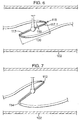
- the dispenser 101 there shown differs as regards it kink valve arrangement and the arrangement for releasing the drug.
- the dispenser body 102 has:
- the flap and kink valves are differently arranged.
- the flap is pivoted at a position spaced from the side of the breath passage 103 and carries an crank 121.1 which extends along the breath passage. At its distal end, the crank is pivotally connected to a Y piece 121.2, itself pivotally connected to trunnions 117.1 on the intermediate tube section 120.
- the arrangement is such that at rest ( Figure 6 ) both kink valves 112,114 are closed.
- the intermediate section 120 is lifted and turned slightly anti-clockwise as the upstream portion 112.1 tightens. This keeps the upstream valve 112 closed, but opens the downstream valve 114.
- the drug is dispensed via the spray nozzle 116 from the intermediate section 120. Similarly exhalation allows recharging of the intermediate section from the upstream tube portion 112.1.
- the arrangement for charging the upstream tube portion differs in that the can is a non-metered dose can.
- a release lever 131 is pivoted to the can housing 106, with an abutment area 132 contacting the can and a handle 133 extending over the central region 134 of the body 102. Gripping of the dispenser can be such that the handle is depressed to release drug and propellant continuously into the upstream tube portion.
- the kink valves 112,114 is always closed, the drug is released only on inhalation.
- the prescribed dose can be inhaled by keeping the handle depressed for a specific number of breaths, which dispense a specific quantity of drug, corresponding to the volume of the intermediate section times the number of inhalations.
- the upstream portion of the tube can be emptied of drug by continued breathing through the device after release of the handle 133.
- the second dispenser - and indeed the first - will normally be used in conjunction with a mouthpiece M or a facemask F or a spacer S or an adapter A for any of these.. These fit the body 102 at the opening 105 and are provided for positively guiding the delivered drug to a patient's airway.
- FIG. 10 an electronic version of the second embodiment is shown.
- kink valves In place of kink valves, it has two electromagnetic valves 212, 214.
- These three are connected to a control circuit 241, powered by a cell 242 and having a counter associated with it. The temperature of the transducer falls with inhalation and rises with exhalation. This can be utilised to program the control circuit to open the downstream valve 214 only on inhalation and open the upstream valve 212 only on exhalation.
- the downstream valve 214 can be opened and closed again during the same inhalation and indeed the upstream valve opened and closed again to charge the intermediate section also during the same inhalation or possibly overlapping the same inhalation and a subsequent exhalation.
- This sequence can all be triggered by an inhalation threshold of air movement through the breath passage, whereby detection of exhalation is not relied upon.
- the device includes a counter 243, which displays the number of breathing/dispensing cycles so that the prescribed quantity of drug can be dispensed.
- a counter 243 which displays the number of breathing/dispensing cycles so that the prescribed quantity of drug can be dispensed.
- the use of the device is exactly analogous to the that of the mechanical/kink-valve embodiment.
- the dispenser there shown differs from that of Figure 10 in having a single electro-mechanical valve 314, with the can 307 being a continuous release can.
- the transducer 321, controller 341, cell 342 and the counter display 343 are physically arranged similarly to those of Figure 10 , but the controller is differently programmed and includes a timer 3411 circuit.
- the programming is such that on an inhalation signal being received from the transducer, the controller causes the valve 314 to open, but only for a time limited to that required for dispensing a dose of drug from the spray nozzle 316 metered by the timer, typically a fraction of a second. On expiry of this period, the controller closes the valve.
- the opening and closing of the valve for dispensing of the drug occurs entirely within the inhalation period and throughout the dispensing, uninhibited flow of drug from the can occurs, with the handle 331 depressing the can for opening of its stem valve (not shown).
- the dispenser continues to be used until the count shown on the counter for a prescribed dosage is reached.
- the counter display can be augmented by an audio or visual alarm such as an LED.
- the controller can be provided with keys for setting the number of inhalations to be counted before alarming.
- the dispenser there shown differs in having a valve (not shown) only in the can 407, which is a metered dose can. It has a can junction 410, connected to a spray nozzle 416 by a drug duct 411, and a transducer 421 with a controller 441 and a counter display 443.
- This dispenser has an external power supply for actuating a solenoid 451 on inhalation under control of the controller.
- the solenoid acts on an arm 431 similar to the handle 331 for depressing the can and releasing a dose metered by the can's internal valve. Thus on successive inhalations, up to a prescribed count, the can is depressed and a dose is inhaled.
- valve and actuator variant for the dispenser of Figure 1 is shown in Figure 13 .
- the valves 512,514 there shown are pinch valves having a diaphragm 561 arranged to close either of a pair of orifices 562,564 under the action of a rocker 565 having a pair of pinch fingers 5621,5641. These are normally biased by leafs 566 to close their orifices and lifted by the rocker 565.
- the latter is pivoted at 522 and actuated by a piston 571 in a cylinder 572, which is open to the breath passage at its respective ends, whereby inhalation pressure differential across the cylinder drives the piston in one direction and exhalation drives it the other way.
- a linkage 573 connects the piston to the rocker for actuation of the valve.
- Such a valve can be electrically actuated by a solenoid in place of the piston and cylinder.
Landscapes
- Health & Medical Sciences (AREA)
- Engineering & Computer Science (AREA)
- Life Sciences & Earth Sciences (AREA)
- Animal Behavior & Ethology (AREA)
- Public Health (AREA)
- Pulmonology (AREA)
- Anesthesiology (AREA)
- Biomedical Technology (AREA)
- Heart & Thoracic Surgery (AREA)
- Hematology (AREA)
- Veterinary Medicine (AREA)
- General Health & Medical Sciences (AREA)
- Bioinformatics & Cheminformatics (AREA)
- Biophysics (AREA)
- Containers And Packaging Bodies Having A Special Means To Remove Contents (AREA)
- Acyclic And Carbocyclic Compounds In Medicinal Compositions (AREA)
- Infusion, Injection, And Reservoir Apparatuses (AREA)
- Materials For Medical Uses (AREA)
- Polysaccharides And Polysaccharide Derivatives (AREA)
- Respiratory Apparatuses And Protective Means (AREA)
- Medical Preparation Storing Or Oral Administration Devices (AREA)
Applications Claiming Priority (2)
| Application Number | Priority Date | Filing Date | Title |
|---|---|---|---|
| GBGB0029612.9A GB0029612D0 (en) | 2000-12-05 | 2000-12-05 | Drug dispenser |
| EP01999400A EP1339446B1 (de) | 2000-12-05 | 2001-12-05 | medizinischer Inhalationsapparat |
Related Parent Applications (2)
| Application Number | Title | Priority Date | Filing Date |
|---|---|---|---|
| EP01999400.3 Division | 2001-12-05 | ||
| EP01999400A Division EP1339446B1 (de) | 2000-12-05 | 2001-12-05 | medizinischer Inhalationsapparat |
Publications (3)
| Publication Number | Publication Date |
|---|---|
| EP2130562A2 true EP2130562A2 (de) | 2009-12-09 |
| EP2130562A3 EP2130562A3 (de) | 2011-01-19 |
| EP2130562B1 EP2130562B1 (de) | 2016-03-23 |
Family
ID=9904459
Family Applications (2)
| Application Number | Title | Priority Date | Filing Date |
|---|---|---|---|
| EP09171687.8A Expired - Lifetime EP2130562B1 (de) | 2000-12-05 | 2001-12-05 | Medikamentenspender |
| EP01999400A Expired - Lifetime EP1339446B1 (de) | 2000-12-05 | 2001-12-05 | medizinischer Inhalationsapparat |
Family Applications After (1)
| Application Number | Title | Priority Date | Filing Date |
|---|---|---|---|
| EP01999400A Expired - Lifetime EP1339446B1 (de) | 2000-12-05 | 2001-12-05 | medizinischer Inhalationsapparat |
Country Status (11)
| Country | Link |
|---|---|
| US (1) | US7225805B2 (de) |
| EP (2) | EP2130562B1 (de) |
| AT (1) | ATE444091T1 (de) |
| AU (2) | AU2002220906B2 (de) |
| CY (2) | CY1110568T1 (de) |
| DE (1) | DE60140071D1 (de) |
| DK (2) | DK1339446T3 (de) |
| ES (2) | ES2573939T3 (de) |
| GB (1) | GB0029612D0 (de) |
| PT (2) | PT1339446E (de) |
| WO (1) | WO2002045783A1 (de) |
Cited By (3)
| Publication number | Priority date | Publication date | Assignee | Title |
|---|---|---|---|---|
| WO2012028889A1 (en) * | 2010-09-03 | 2012-03-08 | Bacon Raymond J | Metering device and dispensing container |
| CN105027134A (zh) * | 2013-02-01 | 2015-11-04 | 爱派库布有限公司 | 魔方与通信系统 |
| EP4134122A1 (de) | 2021-08-10 | 2023-02-15 | Erbe Elektromedizin GmbH | Instrument zur fluidapplikation und klemmeinrichtung |
Families Citing this family (37)
| Publication number | Priority date | Publication date | Assignee | Title |
|---|---|---|---|---|
| CA2439766C (en) | 2001-03-15 | 2008-12-09 | The Government Of The United States Of America As Represented By The Secretary Of The Department Of Health And Human Services, Centers For Disease Control And Prevention | Nebulizer having cooling chamber |
| US7207329B2 (en) * | 2002-10-24 | 2007-04-24 | O-Two Systems International Inc. | Syringe and multi-dose inhaler adapter for a ventilator |
| GB0304000D0 (en) * | 2003-02-21 | 2003-03-26 | Clinical Designs Ltd | Dispenser |
| CA2561845C (en) | 2004-04-02 | 2014-03-25 | The Government Of The United States Of America As Represented By The Secretary Of The Department Of Health And Human Services, Centers For Disease Control And Prevention | Aerosol delivery systems and methods |
| GB0425518D0 (en) * | 2004-11-19 | 2004-12-22 | Clinical Designs Ltd | Substance source |
| GB0428204D0 (en) | 2004-12-23 | 2005-01-26 | Clinical Designs Ltd | Medicament container |
| US20060137681A1 (en) * | 2004-12-28 | 2006-06-29 | Ric Investments, Llc. | Actuator for a metered dose inhaler |
| US7493898B2 (en) * | 2005-04-13 | 2009-02-24 | Healthline Medical, Inc. | Inhalation apparatus |
| US7341056B1 (en) * | 2005-05-25 | 2008-03-11 | The Big Ox, L.L.C. | Portable oxygen supply unit |
| GB0518400D0 (en) | 2005-09-09 | 2005-10-19 | Clinical Designs Ltd | Dispenser |
| WO2008008281A2 (en) | 2006-07-07 | 2008-01-17 | Proteus Biomedical, Inc. | Smart parenteral administration system |
| FR2904297B1 (fr) * | 2006-07-25 | 2008-10-10 | Valois Sas | Dispositif de distribution de produit fluide. |
| RU2009105638A (ru) * | 2006-08-22 | 2010-09-27 | Глакса Груп Лимитед (GB) | Средство приведения в действие для ингалятора |
| DE102006044756A1 (de) * | 2006-09-20 | 2008-04-10 | Boehringer Ingelheim Pharma Gmbh & Co. Kg | Inhalator |
| JP4986687B2 (ja) * | 2007-04-05 | 2012-07-25 | アサヒビール株式会社 | 流体ストッパー装置 |
| GB2451833A (en) * | 2007-08-13 | 2009-02-18 | Bespak Plc | Electrically actuated dose counter for dispensing apparatus |
| WO2009055733A1 (en) | 2007-10-25 | 2009-04-30 | Proteus Biomedical, Inc. | Fluid transfer port information system |
| WO2009067463A1 (en) | 2007-11-19 | 2009-05-28 | Proteus Biomedical, Inc. | Body-associated fluid transport structure evaluation devices |
| US7749191B2 (en) * | 2008-03-20 | 2010-07-06 | Beutlich Lp, Pharmaceuticals | Device and method for drug delivery |
| GB0904040D0 (en) | 2009-03-10 | 2009-04-22 | Euro Celtique Sa | Counter |
| GB0904059D0 (en) | 2009-03-10 | 2009-04-22 | Euro Celtique Sa | Counter |
| MY163805A (en) * | 2009-08-07 | 2017-10-31 | Kind Consumer Ltd | An inhaler |
| EP2531099B1 (de) | 2010-02-01 | 2018-12-12 | Proteus Digital Health, Inc. | Datensammelsystem |
| SG189763A1 (en) | 2010-02-01 | 2013-05-31 | Proteus Digital Health Inc | Two-wrist data gathering system |
| GB201118845D0 (en) | 2011-11-01 | 2011-12-14 | Euro Celtique Sa | Dispenser |
| GB201118842D0 (en) | 2011-11-01 | 2011-12-14 | Euro Celtique Sa | Dispenser cap arrangement |
| CA2856028C (en) * | 2011-12-05 | 2020-01-07 | Chiesi Farmaceutici S.P.A. | Method and system for electronic mdi model |
| US10046123B2 (en) | 2012-10-31 | 2018-08-14 | Inhaletech Llc | Systems and methods for administering pulmonary medications |
| DE102014011271A1 (de) * | 2014-07-29 | 2016-02-04 | Pari GmbH Spezialisten für effektive Inhalation | Vorschaltkammer mit Bedienelement für Inhalator |
| HK1252464B (en) | 2015-07-20 | 2020-05-22 | Pearl Therapeutics, Inc. | Aerosol delivery systems |
| US20170173294A1 (en) * | 2015-12-16 | 2017-06-22 | John H. Renaud | Breathe Clear |
| CN109745142B (zh) * | 2019-03-06 | 2023-08-11 | 山东中医药大学 | 新型大、小鼠定量气雾给药装置 |
| IL275299B (en) * | 2020-06-11 | 2021-07-29 | Dori Guy | A system and method for pumping and evacuating exhaled air from the lungs |
| GB202008867D0 (en) | 2020-06-11 | 2020-07-29 | Dispenser Tech Limited | Improvements in or relating to fluid delivery devices |
| IT202100003521A1 (it) * | 2021-02-16 | 2022-08-16 | Univ Degli Studi Di Parma | Procedimento e apparato per dispensare una quantità predefinita di un composto |
| US12521506B2 (en) | 2021-05-26 | 2026-01-13 | Masimo Corporation | Low deadspace airway adapter |
| KR102795270B1 (ko) * | 2022-07-01 | 2025-04-15 | 주식회사 케이티앤지 | 인헤일러 |
Family Cites Families (10)
| Publication number | Priority date | Publication date | Assignee | Title |
|---|---|---|---|---|
| GB103313A (en) | 1916-05-17 | 1917-01-25 | Harry Haynes | Improvements in the Construction of Damp-proof or Weather-proof Walls. |
| US3187748A (en) * | 1963-04-29 | 1965-06-08 | Merck And Company Inc | Inhalation-actuated aerosol device |
| US4393884A (en) * | 1981-09-25 | 1983-07-19 | Jacobs Allen W | Demand inhaler for oral administration of tobacco, tobacco-like, or other substances |
| EP0461281A1 (de) * | 1990-06-12 | 1991-12-18 | Atochem North America, Inc. | Vorrichtung zum Erfassen eines Luftstroms in einem Durchgang |
| GB9023281D0 (en) | 1990-10-25 | 1990-12-05 | Riker Laboratories Inc | Inhaler |
| US5404871A (en) * | 1991-03-05 | 1995-04-11 | Aradigm | Delivery of aerosol medications for inspiration |
| GB9705657D0 (en) * | 1997-03-19 | 1997-05-07 | Bacon Raymond J | Dispenser |
| ES2656407T3 (es) * | 2000-07-24 | 2018-02-27 | Clinical Designs Limited | Dispensador |
| GB0101944D0 (en) * | 2001-01-25 | 2001-03-07 | Bacon Raymond J | Dispenser |
| US7047964B2 (en) * | 2001-01-25 | 2006-05-23 | Clinical Designs Ltd. | Dispenser for medicament |
-
2000
- 2000-12-05 GB GBGB0029612.9A patent/GB0029612D0/en not_active Ceased
-
2001
- 2001-12-05 US US10/433,861 patent/US7225805B2/en not_active Expired - Lifetime
- 2001-12-05 EP EP09171687.8A patent/EP2130562B1/de not_active Expired - Lifetime
- 2001-12-05 DE DE60140071T patent/DE60140071D1/de not_active Expired - Lifetime
- 2001-12-05 ES ES09171687.8T patent/ES2573939T3/es not_active Expired - Lifetime
- 2001-12-05 AU AU2002220906A patent/AU2002220906B2/en not_active Ceased
- 2001-12-05 PT PT01999400T patent/PT1339446E/pt unknown
- 2001-12-05 AU AU2090602A patent/AU2090602A/xx active Pending
- 2001-12-05 WO PCT/GB2001/005410 patent/WO2002045783A1/en not_active Ceased
- 2001-12-05 EP EP01999400A patent/EP1339446B1/de not_active Expired - Lifetime
- 2001-12-05 PT PT09171687T patent/PT2130562E/pt unknown
- 2001-12-05 AT AT01999400T patent/ATE444091T1/de active
- 2001-12-05 DK DK01999400.3T patent/DK1339446T3/da active
- 2001-12-05 DK DK09171687.8T patent/DK2130562T3/en active
- 2001-12-05 ES ES01999400T patent/ES2332445T3/es not_active Expired - Lifetime
-
2009
- 2009-11-26 CY CY20091101241T patent/CY1110568T1/el unknown
-
2016
- 2016-06-21 CY CY20161100554T patent/CY1117867T1/el unknown
Cited By (9)
| Publication number | Priority date | Publication date | Assignee | Title |
|---|---|---|---|---|
| WO2012028889A1 (en) * | 2010-09-03 | 2012-03-08 | Bacon Raymond J | Metering device and dispensing container |
| CN103180001A (zh) * | 2010-09-03 | 2013-06-26 | 雷蒙德·约翰·培根 | 计量装置以及分配容器 |
| CN103180001B (zh) * | 2010-09-03 | 2016-01-20 | 雷蒙德·约翰·培根 | 计量装置以及分配容器 |
| US9365342B2 (en) | 2010-09-03 | 2016-06-14 | Raymond John Bacon | Metering device and dispensing container |
| US9814848B2 (en) | 2010-09-03 | 2017-11-14 | Raymond John Bacon | Metering device and dispensing container |
| CN105027134A (zh) * | 2013-02-01 | 2015-11-04 | 爱派库布有限公司 | 魔方与通信系统 |
| CN105027134B (zh) * | 2013-02-01 | 2018-01-26 | 爱派库布有限公司 | 魔方与通信系统 |
| EP4134122A1 (de) | 2021-08-10 | 2023-02-15 | Erbe Elektromedizin GmbH | Instrument zur fluidapplikation und klemmeinrichtung |
| US12558527B2 (en) | 2021-08-10 | 2026-02-24 | Erbe Elektromedizin Gmbh | Instrument for fluid application and clamping device |
Also Published As
| Publication number | Publication date |
|---|---|
| ES2332445T3 (es) | 2010-02-05 |
| PT2130562E (pt) | 2016-06-03 |
| US7225805B2 (en) | 2007-06-05 |
| ATE444091T1 (de) | 2009-10-15 |
| EP2130562A3 (de) | 2011-01-19 |
| US20040055596A1 (en) | 2004-03-25 |
| DK1339446T3 (da) | 2010-02-08 |
| PT1339446E (pt) | 2009-11-30 |
| EP1339446A1 (de) | 2003-09-03 |
| WO2002045783A1 (en) | 2002-06-13 |
| CY1117867T1 (el) | 2017-05-17 |
| CY1110568T1 (el) | 2015-04-29 |
| AU2090602A (en) | 2002-06-18 |
| DK2130562T3 (en) | 2016-07-04 |
| EP2130562B1 (de) | 2016-03-23 |
| GB0029612D0 (en) | 2001-01-17 |
| ES2573939T3 (es) | 2016-06-13 |
| AU2002220906B2 (en) | 2006-05-25 |
| DE60140071D1 (de) | 2009-11-12 |
| EP1339446B1 (de) | 2009-09-30 |
Similar Documents
| Publication | Publication Date | Title |
|---|---|---|
| AU2002220906B2 (en) | Drug dispenser | |
| AU2002220906A1 (en) | Drug dispenser | |
| EP0969891B1 (de) | Aerosol-abgabegerät | |
| JP4015943B2 (ja) | 薬剤吸入器 | |
| US3187748A (en) | Inhalation-actuated aerosol device | |
| SI20363A (sl) | Inhalacijska priprava za praškasta zdravila | |
| KR20010075308A (ko) | 흡입기 | |
| CN102470226A (zh) | 吸入器 | |
| JP2004522514A (ja) | 薬剤の投与装置 | |
| IL186698A (en) | A breath-operated inhaler | |
| US20090314372A1 (en) | Fluid flow regulating device | |
| KR102502328B1 (ko) | 흡입기 | |
| WO2006097728A1 (en) | Inhalation devices | |
| EP1861147A1 (de) | Inhaliergeräte | |
| MXPA97004489A (en) | Inhalation device, method for dispersing a pharmaceutically active substance and method for administering a dose of a pharmaceutically acting substance |
Legal Events
| Date | Code | Title | Description |
|---|---|---|---|
| PUAI | Public reference made under article 153(3) epc to a published international application that has entered the european phase |
Free format text: ORIGINAL CODE: 0009012 |
|
| AC | Divisional application: reference to earlier application |
Ref document number: 1339446 Country of ref document: EP Kind code of ref document: P |
|
| AK | Designated contracting states |
Kind code of ref document: A2 Designated state(s): AT BE CH CY DE DK ES FI FR GB GR IE IT LI LU MC NL PT SE TR |
|
| PUAL | Search report despatched |
Free format text: ORIGINAL CODE: 0009013 |
|
| AK | Designated contracting states |
Kind code of ref document: A3 Designated state(s): AT BE CH CY DE DK ES FI FR GB GR IE IT LI LU MC NL PT SE TR |
|
| 17P | Request for examination filed |
Effective date: 20110719 |
|
| GRAP | Despatch of communication of intention to grant a patent |
Free format text: ORIGINAL CODE: EPIDOSNIGR1 |
|
| INTG | Intention to grant announced |
Effective date: 20150127 |
|
| GRAP | Despatch of communication of intention to grant a patent |
Free format text: ORIGINAL CODE: EPIDOSNIGR1 |
|
| INTG | Intention to grant announced |
Effective date: 20150722 |
|
| GRAS | Grant fee paid |
Free format text: ORIGINAL CODE: EPIDOSNIGR3 |
|
| GRAA | (expected) grant |
Free format text: ORIGINAL CODE: 0009210 |
|
| AC | Divisional application: reference to earlier application |
Ref document number: 1339446 Country of ref document: EP Kind code of ref document: P |
|
| AK | Designated contracting states |
Kind code of ref document: B1 Designated state(s): AT BE CH CY DE DK ES FI FR GB GR IE IT LI LU MC NL PT SE TR |
|
| REG | Reference to a national code |
Ref country code: GB Ref legal event code: FG4D |
|
| REG | Reference to a national code |
Ref country code: CH Ref legal event code: EP |
|
| REG | Reference to a national code |
Ref country code: AT Ref legal event code: REF Ref document number: 782524 Country of ref document: AT Kind code of ref document: T Effective date: 20160415 |
|
| REG | Reference to a national code |
Ref country code: IE Ref legal event code: FG4D |
|
| REG | Reference to a national code |
Ref country code: DE Ref legal event code: R096 Ref document number: 60149832 Country of ref document: DE |
|
| REG | Reference to a national code |
Ref country code: PT Ref legal event code: SC4A Free format text: AVAILABILITY OF NATIONAL TRANSLATION Effective date: 20160530 |
|
| REG | Reference to a national code |
Ref country code: ES Ref legal event code: FG2A Ref document number: 2573939 Country of ref document: ES Kind code of ref document: T3 Effective date: 20160613 |
|
| REG | Reference to a national code |
Ref country code: DK Ref legal event code: T3 Effective date: 20160627 |
|
| REG | Reference to a national code |
Ref country code: NL Ref legal event code: FP |
|
| REG | Reference to a national code |
Ref country code: CH Ref legal event code: NV Representative=s name: MARKS AND CLERK (LUXEMBOURG) LLP, CH |
|
| REG | Reference to a national code |
Ref country code: SE Ref legal event code: TRGR |
|
| REG | Reference to a national code |
Ref country code: GR Ref legal event code: EP Ref document number: 20160401331 Country of ref document: GR Effective date: 20160729 |
|
| REG | Reference to a national code |
Ref country code: FR Ref legal event code: PLFP Year of fee payment: 16 |
|
| REG | Reference to a national code |
Ref country code: DE Ref legal event code: R097 Ref document number: 60149832 Country of ref document: DE |
|
| PLBE | No opposition filed within time limit |
Free format text: ORIGINAL CODE: 0009261 |
|
| STAA | Information on the status of an ep patent application or granted ep patent |
Free format text: STATUS: NO OPPOSITION FILED WITHIN TIME LIMIT |
|
| 26N | No opposition filed |
Effective date: 20170102 |
|
| REG | Reference to a national code |
Ref country code: FR Ref legal event code: PLFP Year of fee payment: 17 |
|
| PGFP | Annual fee paid to national office [announced via postgrant information from national office to epo] |
Ref country code: TR Payment date: 20171205 Year of fee payment: 17 |
|
| REG | Reference to a national code |
Ref country code: DE Ref legal event code: R082 Ref document number: 60149832 Country of ref document: DE Representative=s name: MARKS & CLERK (LUXEMBOURG) LLP, LU Ref country code: DE Ref legal event code: R081 Ref document number: 60149832 Country of ref document: DE Owner name: CLINICAL DESIGNS LTD., GB Free format text: FORMER OWNER: BACON, RAYMOND JOHN, EMSWORTH, HAMPSHIRE, GB |
|
| REG | Reference to a national code |
Ref country code: LU Ref legal event code: PD Owner name: CLINICAL DESIGNS LIMITED; GB Free format text: FORMER OWNER: BACON RAYMOND JOHN Effective date: 20180918 |
|
| REG | Reference to a national code |
Ref country code: ES Ref legal event code: PC2A Owner name: CLINICAL DESIGNS LIMITED Effective date: 20181115 Ref country code: NL Ref legal event code: PD Owner name: CLINICAL DESIGNS LIMITED; GB Free format text: DETAILS ASSIGNMENT: CHANGE OF OWNER(S), ASSIGNMENT; FORMER OWNER NAME: BACON, RAYMOND JOHN Effective date: 20180917 |
|
| REG | Reference to a national code |
Ref country code: BE Ref legal event code: FP Effective date: 20160620 Ref country code: BE Ref legal event code: PD Owner name: CLINICAL DESIGNS LIMITED; GB Free format text: DETAILS ASSIGNMENT: CHANGE OF OWNER(S), CESSION; FORMER OWNER NAME: BACON, RAYMOND JOHN Effective date: 20181010 |
|
| REG | Reference to a national code |
Ref country code: AT Ref legal event code: PC Ref document number: 782524 Country of ref document: AT Kind code of ref document: T Owner name: CLINICAL DESIGNS LIMITED, GB Effective date: 20181115 |
|
| PGFP | Annual fee paid to national office [announced via postgrant information from national office to epo] |
Ref country code: MC Payment date: 20181226 Year of fee payment: 18 Ref country code: FI Payment date: 20181220 Year of fee payment: 18 Ref country code: LU Payment date: 20181219 Year of fee payment: 18 Ref country code: DK Payment date: 20181221 Year of fee payment: 18 Ref country code: PT Payment date: 20181121 Year of fee payment: 18 Ref country code: AT Payment date: 20181220 Year of fee payment: 18 Ref country code: DE Payment date: 20181210 Year of fee payment: 18 Ref country code: NL Payment date: 20181219 Year of fee payment: 18 Ref country code: SE Payment date: 20181219 Year of fee payment: 18 Ref country code: GR Payment date: 20181219 Year of fee payment: 18 Ref country code: IE Payment date: 20181220 Year of fee payment: 18 |
|
| REG | Reference to a national code |
Ref country code: AT Ref legal event code: UEP Ref document number: 782524 Country of ref document: AT Kind code of ref document: T Effective date: 20160323 |
|
| PGFP | Annual fee paid to national office [announced via postgrant information from national office to epo] |
Ref country code: BE Payment date: 20181217 Year of fee payment: 18 Ref country code: FR Payment date: 20181220 Year of fee payment: 18 Ref country code: CH Payment date: 20181218 Year of fee payment: 18 Ref country code: IT Payment date: 20181219 Year of fee payment: 18 Ref country code: GB Payment date: 20181218 Year of fee payment: 18 |
|
| PGFP | Annual fee paid to national office [announced via postgrant information from national office to epo] |
Ref country code: ES Payment date: 20190123 Year of fee payment: 18 Ref country code: CY Payment date: 20190128 Year of fee payment: 18 |
|
| REG | Reference to a national code |
Ref country code: GB Ref legal event code: 732E Free format text: REGISTERED BETWEEN 20190503 AND 20190508 |
|
| REG | Reference to a national code |
Ref country code: CH Ref legal event code: NV Representative=s name: SERVOPATENT GMBH, CH Ref country code: CH Ref legal event code: PUE Owner name: CLINICAL DESIGNS LIMITED, GB Free format text: FORMER OWNER: BACON, RAYMOND JOHN, GB |
|
| REG | Reference to a national code |
Ref country code: CH Ref legal event code: PCAR Free format text: NEW ADDRESS: WANNERSTRASSE 9/1, 8045 ZUERICH (CH) |
|
| REG | Reference to a national code |
Ref country code: DE Ref legal event code: R119 Ref document number: 60149832 Country of ref document: DE |
|
| REG | Reference to a national code |
Ref country code: FI Ref legal event code: MAE |
|
| REG | Reference to a national code |
Ref country code: DK Ref legal event code: EBP Effective date: 20191231 |
|
| REG | Reference to a national code |
Ref country code: SE Ref legal event code: EUG |
|
| PG25 | Lapsed in a contracting state [announced via postgrant information from national office to epo] |
Ref country code: CY Free format text: LAPSE BECAUSE OF NON-PAYMENT OF DUE FEES Effective date: 20191205 Ref country code: FI Free format text: LAPSE BECAUSE OF NON-PAYMENT OF DUE FEES Effective date: 20191205 |
|
| REG | Reference to a national code |
Ref country code: CH Ref legal event code: PL |
|
| REG | Reference to a national code |
Ref country code: NL Ref legal event code: MM Effective date: 20200101 |
|
| REG | Reference to a national code |
Ref country code: AT Ref legal event code: MM01 Ref document number: 782524 Country of ref document: AT Kind code of ref document: T Effective date: 20191205 |
|
| REG | Reference to a national code |
Ref country code: BE Ref legal event code: MM Effective date: 20191231 |
|
| PG25 | Lapsed in a contracting state [announced via postgrant information from national office to epo] |
Ref country code: MC Free format text: LAPSE BECAUSE OF NON-PAYMENT OF DUE FEES Effective date: 20200102 |
|
| GBPC | Gb: european patent ceased through non-payment of renewal fee |
Effective date: 20191205 |
|
| PG25 | Lapsed in a contracting state [announced via postgrant information from national office to epo] |
Ref country code: NL Free format text: LAPSE BECAUSE OF NON-PAYMENT OF DUE FEES Effective date: 20200101 |
|
| PG25 | Lapsed in a contracting state [announced via postgrant information from national office to epo] |
Ref country code: IT Free format text: LAPSE BECAUSE OF NON-PAYMENT OF DUE FEES Effective date: 20191205 Ref country code: LU Free format text: LAPSE BECAUSE OF NON-PAYMENT OF DUE FEES Effective date: 20191205 Ref country code: FR Free format text: LAPSE BECAUSE OF NON-PAYMENT OF DUE FEES Effective date: 20191231 Ref country code: DE Free format text: LAPSE BECAUSE OF NON-PAYMENT OF DUE FEES Effective date: 20200701 Ref country code: IE Free format text: LAPSE BECAUSE OF NON-PAYMENT OF DUE FEES Effective date: 20191205 Ref country code: GB Free format text: LAPSE BECAUSE OF NON-PAYMENT OF DUE FEES Effective date: 20191205 Ref country code: GR Free format text: LAPSE BECAUSE OF NON-PAYMENT OF DUE FEES Effective date: 20200707 Ref country code: SE Free format text: LAPSE BECAUSE OF NON-PAYMENT OF DUE FEES Effective date: 20191206 Ref country code: PT Free format text: LAPSE BECAUSE OF NON-PAYMENT OF DUE FEES Effective date: 20200709 |
|
| PG25 | Lapsed in a contracting state [announced via postgrant information from national office to epo] |
Ref country code: AT Free format text: LAPSE BECAUSE OF NON-PAYMENT OF DUE FEES Effective date: 20191205 Ref country code: CH Free format text: LAPSE BECAUSE OF NON-PAYMENT OF DUE FEES Effective date: 20191231 Ref country code: BE Free format text: LAPSE BECAUSE OF NON-PAYMENT OF DUE FEES Effective date: 20191231 Ref country code: LI Free format text: LAPSE BECAUSE OF NON-PAYMENT OF DUE FEES Effective date: 20191231 |
|
| PG25 | Lapsed in a contracting state [announced via postgrant information from national office to epo] |
Ref country code: DK Free format text: LAPSE BECAUSE OF NON-PAYMENT OF DUE FEES Effective date: 20191231 |
|
| REG | Reference to a national code |
Ref country code: ES Ref legal event code: FD2A Effective date: 20210526 |
|
| PG25 | Lapsed in a contracting state [announced via postgrant information from national office to epo] |
Ref country code: ES Free format text: LAPSE BECAUSE OF NON-PAYMENT OF DUE FEES Effective date: 20191206 |
|
| PG25 | Lapsed in a contracting state [announced via postgrant information from national office to epo] |
Ref country code: TR Free format text: LAPSE BECAUSE OF NON-PAYMENT OF DUE FEES Effective date: 20191205 |