EP2130652B1 - Outil électrique doté d'une ventilation d'embrayage - Google Patents
Outil électrique doté d'une ventilation d'embrayage Download PDFInfo
- Publication number
- EP2130652B1 EP2130652B1 EP08010192A EP08010192A EP2130652B1 EP 2130652 B1 EP2130652 B1 EP 2130652B1 EP 08010192 A EP08010192 A EP 08010192A EP 08010192 A EP08010192 A EP 08010192A EP 2130652 B1 EP2130652 B1 EP 2130652B1
- Authority
- EP
- European Patent Office
- Prior art keywords
- sealing element
- opening
- power tool
- flow
- recited
- Prior art date
- Legal status (The legal status is an assumption and is not a legal conclusion. Google has not performed a legal analysis and makes no representation as to the accuracy of the status listed.)
- Active
Links
Images

Classifications
-
- B—PERFORMING OPERATIONS; TRANSPORTING
- B25—HAND TOOLS; PORTABLE POWER-DRIVEN TOOLS; MANIPULATORS
- B25D—PERCUSSIVE TOOLS
- B25D17/00—Details of, or accessories for, portable power-driven percussive tools
- B25D17/20—Devices for cleaning or cooling tool or work
-
- B—PERFORMING OPERATIONS; TRANSPORTING
- B01—PHYSICAL OR CHEMICAL PROCESSES OR APPARATUS IN GENERAL
- B01D—SEPARATION
- B01D45/00—Separating dispersed particles from gases or vapours by gravity, inertia, or centrifugal forces
- B01D45/04—Separating dispersed particles from gases or vapours by gravity, inertia, or centrifugal forces by utilising inertia
- B01D45/06—Separating dispersed particles from gases or vapours by gravity, inertia, or centrifugal forces by utilising inertia by reversal of direction of flow
-
- B—PERFORMING OPERATIONS; TRANSPORTING
- B23—MACHINE TOOLS; METAL-WORKING NOT OTHERWISE PROVIDED FOR
- B23Q—DETAILS, COMPONENTS, OR ACCESSORIES FOR MACHINE TOOLS, e.g. ARRANGEMENTS FOR COPYING OR CONTROLLING; MACHINE TOOLS IN GENERAL CHARACTERISED BY THE CONSTRUCTION OF PARTICULAR DETAILS OR COMPONENTS; COMBINATIONS OR ASSOCIATIONS OF METAL-WORKING MACHINES, NOT DIRECTED TO A PARTICULAR RESULT
- B23Q11/00—Accessories fitted to machine tools for keeping tools or parts of the machine in good working condition or for cooling work; Safety devices specially combined with or arranged in, or specially adapted for use in connection with, machine tools
- B23Q11/10—Arrangements for cooling or lubricating tools or work
- B23Q11/1069—Filtration systems specially adapted for cutting liquids
-
- B—PERFORMING OPERATIONS; TRANSPORTING
- B25—HAND TOOLS; PORTABLE POWER-DRIVEN TOOLS; MANIPULATORS
- B25D—PERCUSSIVE TOOLS
- B25D16/00—Portable percussive machines with superimposed rotation, the rotational movement of the output shaft of a motor being modified to generate axial impacts on the tool bit
- B25D16/006—Mode changers; Mechanisms connected thereto
-
- B—PERFORMING OPERATIONS; TRANSPORTING
- B25—HAND TOOLS; PORTABLE POWER-DRIVEN TOOLS; MANIPULATORS
- B25D—PERCUSSIVE TOOLS
- B25D2250/00—General details of portable percussive tools; Components used in portable percussive tools
- B25D2250/185—Pressure equalising means between sealed chambers
-
- B—PERFORMING OPERATIONS; TRANSPORTING
- B25—HAND TOOLS; PORTABLE POWER-DRIVEN TOOLS; MANIPULATORS
- B25D—PERCUSSIVE TOOLS
- B25D2250/00—General details of portable percussive tools; Components used in portable percussive tools
- B25D2250/365—Use of seals
Definitions
- the present invention relates to a power tool according to the preamble of claim 1, in particular a drill or chisel comprising a lubricated arranged in a, in particular airtight, sealed gear housing gear, wherein the gear chamber via a vent passage in fluid communication with the atmosphere, and a in the air duct arranged, air-permeable sealing element.
- a power tool is from the DE 19 628 946 A known.
- Such a power tool is for example also from the EP 1 252 976 A1
- the transmission chamber is open to the atmosphere via a narrow channel and a filter adjoining this channel.
- the filter element may be, for example, a felt.
- the gear unit is lubricated with oil or oil-like lubricant, there is a risk that the felt will become saturated with oil due to capillary action and the gearbox will soon become leaky (loss of oil due to capillary action).
- a similar problem also arises when using grease or greasy lubricant.
- the felt works like a sieve and separates the fat in its components.
- the base oil is absorbed by the felt by capillary action, whereas the soaps from the grease stick to the surface of the felt and form a thick layer. This layer seals the felt, so that although a further loss of lubricant is prevented, but at the same time no ventilation of the gear housing is more guaranteed.
- the venting is necessary, however, because the air pressure within the gear housing of the rotary or chisel hammer due to temperature changes and the operation of the percussion continuous fluctuations subject and a pressure equalization with the atmosphere must be provided.
- the object of the present invention is based on a power tool of the type mentioned in such a way that a safer and permanent ventilation can be ensured substantially without loss of lubricant.
- the invention is based on the idea in the path or channel that takes the air to pressure equalization of the gear compartment to the atmosphere to provide a labyrinth-like sealing element that allows air circulation at positive or negative pressure in the gear compartment, without the lubricant by capillary action from the transmission can be, in which the path from the gear room is extended to the outside.
- a power tool according to the invention which is in particular a drill or chisel hammer, comprises a lubricated transmission arranged in a, in particular substantially airtight, sealed gear compartment, wherein the gear box is in fluid communication with the atmosphere via a venting channel and in which Venting channel disposed, air-through sealing element that allows air circulation at high or low pressure in the gear compartment between the atmosphere and the gear compartment.
- This sealing element according to the invention is designed such that it extends the vent channel labyrinth-like, so that the air circulation is still possible, however, a lubricant passage is prevented from the gear compartment to the sealing element over to the atmosphere.
- the sealing element is configured such that it has an opening facing the gear housing, ie an opening which opens directly or indirectly into the gear chamber.
- two flow channels extending from the mouth opening are provided here so that the air flowing out of the gear chamber, for example, in the case of overpressure, can flow into the mouth opening and from there flow into the two separate flow channels in different directions. This is especially to avoid a lubricant jam, z. B.
- a fatty block makes sense.
- the accumulated fat is forced out of the mouth opening into only one of the two flow channels in the event of an overpressure situation, so that there is always a flow channel for the passage of air. This contributes to a reliable and safe ventilation.
- the sealing element may be formed of rubber or a rubber-like material.
- the vent channel comprises an opening which opens into the gear chamber, wherein it is preferred here that the sealing element connects substantially directly to the opening.
- the power tool has a switching element, preferably a gear change switch, wherein the switching element preferably has a projecting into the gear housing nozzle by the vent channel is formed with the sealing element.
- a switching element is operable to operate the power tool from the outside, to switch a component in the interior of the power tool. Therefore, such a switching element is an interface between the interior of the power tool and the environment and thus the atmosphere. This interface can be configured as a leak and can be used to save space and cost to form the vent channel.
- a gear change is particularly preferred.
- a mechanical connection between the switching element and one or more transmission elements exist. Ie. There is a connection between the switch and the gear compartment, so that essentially no additional elements have to be provided to form the ventilation channel.
- the sealing element has at least one, but preferably a plurality of floors, each composed of at least one (preferably only one) opening into the respective floor mouth opening and two continuing from the mouth opening flow channels.
- the sealing element which, as already mentioned, may be made of rubber or a rubber-like material, is cast, in particular injection-molded.
- the sealing element has a plurality of grooves arranged one behind the other in the direction of the ventilation channel.
- the sealing element has a plurality of grooves running perpendicular to a longitudinal axis of the ventilation channel and spaced in the longitudinal direction of the ventilation channel. These grooves in each case form the mentioned flow channels and are separated by walls which are circumferential relative to the longitudinal direction of the ventilation channel and are spaced apart in the longitudinal direction of the flow channel.
- These walls each have one, preferably only one, opening forming the orifice.
- the wall is completely broken from one side to the other in the longitudinal direction of the vent channel, so that the opening creates a connection between two adjacent in the longitudinal direction of the vent channel grooves or flow channels.
- These openings are alternately on opposite sides, z. B. a front and a back, provided the sealing element, so that a straight flow from one opening to the next is not possible.
- the apertures or mouth openings are not arranged centrally in the walls and on the corresponding side, but in any manner offset in the walls.
- the walls circumferentially seal against the vent passage substantially airtight, so that neither a lubricant flow nor an air flow between the surface of the walls and the inner surface of the vent passage is allowed past the sealing element.
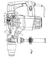
- the illustrated power tool is a drill and chisel hammer with a non-visible electric motor as a drive unit that offers a drill or chisel hammer function via a not visible or illustrated gear. It can be switched over a gear change switch 20 between a rotary hammer and a chisel hammer operation.
- the gear selector causes by a mechanical connection to the gear either the transmission of the rotational movement of the electric motor to the drill chuck (drill hammer operation) or a corresponding removal of this rotational movement (chisel hammer mode).
- the mechanical connection or switching of the transmission is irrelevant to the present invention and is therefore not explained in detail.
- the transmission is accommodated in a transmission housing, which in the illustrated embodiment composed of a housing body 21 and a cover 22.
- a gear chamber 23 is formed, which receives the oil-lubricated in the present case and not shown gear. Due to temperature changes during operation and the impact function of the percussion arise during operation of the power tool in the transmission chamber 23 pressure fluctuations. Ie. It can create an overpressure or a negative pressure, which must be balanced out to the atmosphere.
- the gear changeover switch 20 has a connecting piece 24, which sits in a recess 25 of the gear housing cover 22 and at the same time is rotatably fixed on the gear housing cover 22 via non-visible latching connections.
- the transmission change-over switch 20 comprises a handling element 27, which is graspable for actuating the transmission changeover switch 20. Facing the gear housing cover 22, a cavity 28 is provided in this handling member 27, which is formed by a recess in the handling member 27 and closed by a surface of the gear housing cover 22.
- a venting channel 26 is provided in the nozzle 24, which communicates via a connecting bore 29 with the space 28 in connection.
- the vent channel 26 has an opening 30 which opens into the gear chamber 23. Due to the fluid connection between the space 28 and the atmosphere via the interface between the handling member 27 and the outer surface of the gear housing cover 22, therefore, there is a space 28, the bore 29 and the vent channel 26 a Fluid communication between the atmosphere and the gear room 23rd
- the sealing element 40 is preferably made of rubber or rubbery material and in particular cast, for. B. injection molded. It tapers from one end facing the opening 30 to its opposite end and into the Fig. 1 and 2 shown venting channel 26 is the same kind, that is tapered away from the opening 30. This is predefined in particular by the gear change switch 20, which is an injection-molded part, so that the tapering shape of the recess, which forms the ventilation channel 26, is necessary for removal from the mold.
- the sealing element sits non-positively in the vent channel, so that no additional attachment is required.
- the sealing element 40 has an orifice 41.
- this mouth opening 41 is arranged on the side of the sealing element 40 facing the opening 30 and thus the gear chamber 23. From this mouth opening 41, two flow channels 42 and 43 continue.
- the sealing element 40 of the illustrated embodiment further comprises five floors 1-5 (see Fig. 2 ), each composed of an orifice 41 and the two of the mouth opening 41 continuing flow channels 42, 43 composed.
- the sealing element 40 is formed by a plurality of grooves 44 which encircle the flow channels 42, 43 and are perpendicular to the longitudinal direction of the sealing element 40.
- the grooves 44 are spaced apart from one another in the longitudinal direction of the sealing element 40 and separated by walls 45.
- the walls are designed to run circumferentially perpendicular to the longitudinal direction of the sealing element 40 and each have an opening 46 in the longitudinal direction.
- the opening of the walls is designed such that they each connect two of the grooves 44.
- the next to the gear chamber 23, that is provided at the thicker end of the sealing member 40 opening 46 connects the first groove 44 via the opening 30 with the gear chamber 23 and therefore is the gear chamber facing the mouth opening.
- the openings 46 of adjacent walls 45 are each provided diametrically opposite on opposite sides of the sealing element 40.
- the openings 46 do not necessarily have to be diametrically opposed, ie offset by 180 °, be arranged on adjacent walls 45, but can also be arranged otherwise staggered.
- At least one sealing lip 47 is provided which seals the walls 45 circumferentially against the inner wall of the vent channel 26 so that an air and lubricant passage, between the outer surfaces of the walls 45 and the inner surface of the vent passage 26 is prevented.
- the sealing element according to the invention therefore offers numerous advantages. First, it is inexpensive to produce. On the other hand, the placement and design in the gear selector space-saving and easy to implement without the integration or implementation of other elements or configurations. However, without having to give up these advantages, the sealing element of the present invention provides a safe and reliable venting without the risk of lubricant leakage and thus the cost-effective and space-saving replacement of the known filter as a sealing element.
- the grooves 44 and thus the flow channels 42, 43 need not necessarily and necessarily perpendicular to the longitudinal extent of the vent channel 26 and / or the sealing element 40 extend, but may also be formed inclined or composed of longitudinal and transverse elements or sections.
- the openings 41 formed by the apertures 46 need not necessarily extend in the longitudinal direction, but may also be formed inclined.
- the opening 41 need not necessarily be provided diametrically opposite one another on different sides and alternately in the walls 45, but may be formed differently offset.
- vent channel does not necessarily have to be integrated in a switching element and / or the sealing element in the Vent channel of the switching element sitting.
- the gear housing cover 22 a corresponding nozzle which opens into the gear chamber 23 and is in communication with the atmosphere to provide, in which then the venting channel would be provided with sealing element.
- the transmission does not necessarily have to be lubricated with oil, but it could also be a grease lubrication and / or another oily or greasy lubricant or any other lubricant used.
- oil a grease lubrication and / or another oily or greasy lubricant or any other lubricant used.
Landscapes
- Engineering & Computer Science (AREA)
- Mechanical Engineering (AREA)
- Chemical & Material Sciences (AREA)
- Chemical Kinetics & Catalysis (AREA)
- Percussive Tools And Related Accessories (AREA)
- General Details Of Gearings (AREA)
Claims (7)
- Outil électrique, en particulier marteau perforateur et/ou marteau burineur, comprenant une transmission lubrifiée et disposée dans une chambre de transmission (23) étanchéifiée, la chambre de transmission (23) étant en liaison fluidique avec l'atmosphère au moyen d'un canal de purge (26), et un élément d'étanchéité (40) disposé dans le canal de purge (26) et laissant passer l'air, qui prolonge le canal de purge (26) à la façon d'un labyrinthe, de sorte qu'une traversée de lubrifiant dans l'élément d'étanchéité (40) est empêchée, caractérisé en ce que l'élément d'étanchéité (40) présente sur le côté tourné vers la chambre de transmission (23) un orifice d'embouchure (41) et deux canaux d'écoulement (42, 43) se prolongeant à partir de l'orifice d'embouchure (41).
- Outil électrique selon la revendication 1, sur lequel l'élément d'étanchéité (40) se raccorde sensiblement directement à un orifice (30) du canal de purge (26) dans la chambre de transmission (23).
- Outil électrique selon la revendication 1 ou 2, comprenant également un élément de commutation (20), de préférence un inverseur de transmission, avec une tubulure (24) dépassant dans la chambre de transmission (23), dans laquelle est conçu le canal de purge (26) avec l'élément d'étanchéité (40).
- Outil électrique selon l'une quelconque des revendications précédentes, sur lequel l'élément d'étanchéité (40) présente au moins un, de préférence plusieurs étages (1-5), lesquels comprennent chacun un orifice d'embouchure (41) débouchant dans l'étage (1-5) concerné et deux canaux d'écoulement (42, 43) se prolongeant à partir de l'orifice d'embouchure.
- Outil électrique selon la revendication 4, sur lequel l'élément d'étanchéité (40) présente plusieurs rainures (44) disposées les unes derrière les autres dans le sens longitudinal du canal de purge (26), lesquelles rainures forment respectivement les canaux d'écoulement (42, 43) et à chaque fois un percement (46) formant les orifices d'embouchure (41) est conçu dans les parois (45) séparant les rainures (44), les percements (46) étant prévus alternativement sur des côtés opposés de l'élément d'étanchéité (40).
- Outil électrique selon la revendication 5, sur lequel les parois (45) assurent l'étanchéité sensiblement hermétique sur le pourtour par rapport au canal de purge (26).
- Outil électrique selon la revendication 6, sur lequel, pour l'étanchéité périphérique, une lèvre d'étanchéité (47) périphérique est disposée sur les parois (45).
Priority Applications (3)
| Application Number | Priority Date | Filing Date | Title |
|---|---|---|---|
| EP08010192A EP2130652B1 (fr) | 2008-06-04 | 2008-06-04 | Outil électrique doté d'une ventilation d'embrayage |
| US12/477,398 US7946353B2 (en) | 2008-06-04 | 2009-06-03 | Power tool having a transmission vent |
| CN200910146452XA CN101596709B (zh) | 2008-06-04 | 2009-06-04 | 具有传输通气孔道的电动工具 |
Applications Claiming Priority (1)
| Application Number | Priority Date | Filing Date | Title |
|---|---|---|---|
| EP08010192A EP2130652B1 (fr) | 2008-06-04 | 2008-06-04 | Outil électrique doté d'une ventilation d'embrayage |
Publications (2)
| Publication Number | Publication Date |
|---|---|
| EP2130652A1 EP2130652A1 (fr) | 2009-12-09 |
| EP2130652B1 true EP2130652B1 (fr) | 2011-09-14 |
Family
ID=39864671
Family Applications (1)
| Application Number | Title | Priority Date | Filing Date |
|---|---|---|---|
| EP08010192A Active EP2130652B1 (fr) | 2008-06-04 | 2008-06-04 | Outil électrique doté d'une ventilation d'embrayage |
Country Status (3)
| Country | Link |
|---|---|
| US (1) | US7946353B2 (fr) |
| EP (1) | EP2130652B1 (fr) |
| CN (1) | CN101596709B (fr) |
Families Citing this family (19)
| Publication number | Priority date | Publication date | Assignee | Title |
|---|---|---|---|---|
| USD618529S1 (en) * | 2009-01-08 | 2010-06-29 | Black & Decker Inc. | Hammer drill |
| USD618530S1 (en) * | 2009-05-05 | 2010-06-29 | Black & Decker Inc. | Hammer |
| USD626813S1 (en) * | 2009-05-05 | 2010-11-09 | Black & Decker Inc. | Hammer |
| USD618531S1 (en) * | 2009-05-05 | 2010-06-29 | Black & Decker Inc. | Hammer |
| USD625981S1 (en) * | 2009-05-05 | 2010-10-26 | Black & Decker Inc. | Hammer |
| USD615838S1 (en) * | 2009-09-02 | 2010-05-18 | Robert Bosch Gmbh | Hammer drill |
| JP5428848B2 (ja) * | 2009-12-25 | 2014-02-26 | 日立工機株式会社 | 電動工具 |
| USD645317S1 (en) * | 2010-02-09 | 2011-09-20 | Aeg Electric Tools Gmbh | Drill hammer |
| USD676731S1 (en) * | 2010-11-29 | 2013-02-26 | Robert Bosch Gmbh | Hammer drill |
| CN102632484B (zh) * | 2011-02-13 | 2015-05-06 | 南京德朔实业有限公司 | 动力工具 |
| USD691011S1 (en) * | 2011-05-10 | 2013-10-08 | Hilti Aktiengesellschaft | Cordless rotary hammer |
| USD695086S1 (en) * | 2011-05-11 | 2013-12-10 | Hilti Aktiengesellschaft | Rotary hammer with dust reduction system |
| USD716626S1 (en) * | 2013-05-02 | 2014-11-04 | Black & Decker Inc. | Drill |
| EP2821183B1 (fr) | 2013-07-05 | 2017-06-21 | Black & Decker Inc. | Marteau perforateur |
| DE102013221126A1 (de) * | 2013-10-17 | 2015-04-23 | Robert Bosch Gmbh | Handwerkzeugmaschine |
| JP1521659S (fr) * | 2014-09-26 | 2015-04-13 | ||
| CN106895131B (zh) * | 2015-12-21 | 2024-01-23 | 博世电动工具(中国)有限公司 | 密封通气装置及包括其的设备 |
| CN108326804A (zh) * | 2017-01-20 | 2018-07-27 | 苏州宝时得电动工具有限公司 | 一种电动工具的减速箱压力平衡装置 |
| USD1034128S1 (en) * | 2022-02-07 | 2024-07-09 | Robert Bosch Gmbh | Hammer drill |
Family Cites Families (20)
| Publication number | Priority date | Publication date | Assignee | Title |
|---|---|---|---|---|
| DE1220361B (de) * | 1965-05-07 | 1966-07-07 | Duss Maschf | Schmiereinreinrichtung an einem Bohrhammer zur Steinbearbeitung |
| DE2343014B2 (de) * | 1973-08-25 | 1978-04-27 | Licentia Patent-Verwaltungs-Gmbh, 6000 Frankfurt | Pneumatischer Bohrhammer |
| JPS6043278B2 (ja) * | 1977-02-04 | 1985-09-27 | 芝浦メカトロニクス株式会社 | ハンマドリル |
| DE2709616A1 (de) * | 1977-03-05 | 1978-09-07 | Impex Essen Vertrieb | Entlueftungseinrichtung fuer getrieberaeume von insbesondere handwerkzeugen, z.b. bohr- und meisselhaemmern |
| US4298073A (en) * | 1979-05-03 | 1981-11-03 | Eagle-Picher Industries, Inc. | Drill head |
| US4487271A (en) * | 1982-02-12 | 1984-12-11 | Pomeroy Dan M | Portable core drill |
| DE3320426C3 (de) * | 1983-06-06 | 1998-03-26 | Hilti Ag | Belüftung für den Gehäuseraum eines Bohr- oder Meisselgerätes |
| US4858701A (en) * | 1987-11-30 | 1989-08-22 | Weyer Paul P | Fluid-powered impact device and tool therefor |
| US5492183A (en) * | 1991-04-11 | 1996-02-20 | The Sollami Company | Drill head unit |
| JP3292972B2 (ja) * | 1996-03-29 | 2002-06-17 | 株式会社マキタ | 打撃工具 |
| DE19628946A1 (de) * | 1996-07-18 | 1998-01-22 | Bosch Gmbh Robert | Handwerkzeugmaschine |
| GB0109747D0 (en) | 2001-04-20 | 2001-06-13 | Black & Decker Inc | Hammer |
| US7032683B2 (en) * | 2001-09-17 | 2006-04-25 | Milwaukee Electric Tool Corporation | Rotary hammer |
| RU2311282C2 (ru) * | 2004-11-05 | 2007-11-27 | Хитачи Коки Ко., Лтд. | Приводной инструмент с устройством для предотвращения утечки смазочного материала (варианты) |
| JP4470696B2 (ja) * | 2004-11-05 | 2010-06-02 | 日立工機株式会社 | 電動工具 |
| DE202004019045U1 (de) * | 2004-12-09 | 2005-03-17 | Mann & Hummel Gmbh | Lufttrocknersystem |
| EP1674211A1 (fr) * | 2004-12-23 | 2006-06-28 | BLACK & DECKER INC. | Carter pour un outil motorisé |
| JP4461062B2 (ja) * | 2005-06-02 | 2010-05-12 | 株式会社マキタ | 作業工具 |
| JP4497040B2 (ja) * | 2005-07-08 | 2010-07-07 | 日立工機株式会社 | 振動ドリル |
| US7770660B2 (en) * | 2007-11-21 | 2010-08-10 | Black & Decker Inc. | Mid-handle drill construction and assembly process |
-
2008
- 2008-06-04 EP EP08010192A patent/EP2130652B1/fr active Active
-
2009
- 2009-06-03 US US12/477,398 patent/US7946353B2/en active Active
- 2009-06-04 CN CN200910146452XA patent/CN101596709B/zh not_active Expired - Fee Related
Also Published As
| Publication number | Publication date |
|---|---|
| CN101596709A (zh) | 2009-12-09 |
| US7946353B2 (en) | 2011-05-24 |
| CN101596709B (zh) | 2013-06-12 |
| EP2130652A1 (fr) | 2009-12-09 |
| US20090301746A1 (en) | 2009-12-10 |
Similar Documents
| Publication | Publication Date | Title |
|---|---|---|
| EP2130652A1 (fr) | Outil électrique doté d'une ventilation d'embrayage | |
| EP2496852B1 (fr) | Douille pour une unité d'entraînement et unité d'entraînement | |
| EP1261820B1 (fr) | Garniture d'etancheite en forme de labyrinthe placee entre des pieces rotatives | |
| DE102011076465B4 (de) | Zentrifugalabscheider zum Abscheiden von Ölnebel aus dem Kurbelgehäuseentlüftungsgas einer Brennkraftmaschine | |
| DE102009050359B4 (de) | Spindelmotor | |
| DE102014204088A1 (de) | Ölführung eines Getriebes für ein Fahrzeug | |
| DE112013000924T5 (de) | Labyrinthdichtung | |
| EP4433725B1 (fr) | Dispositif d'entraînement pour essieu électrifié de véhicule | |
| EP3194812B1 (fr) | Moyen de guidage destiné à être disposé au niveau d'une boîte de vitesses et/ou d'un embrayage d'un véhicule automobile | |
| DE102018125460B4 (de) | Getriebeanordnung für ein Fahrzeug sowie elektrischer Antrieb mit der Getriebeanordnung | |
| EP3063437A1 (fr) | Bague d'étanchéité d'arbre | |
| DE102006030450A1 (de) | Hydraulische Stellvorrichtung für die Betätigung einer Schaltstange insbesondere eines Schaltgetriebes für Kraftfahrzeuge | |
| DE102006058980B4 (de) | Flügelzellenpumpe | |
| WO2007062814A1 (fr) | Systeme de joint destine a une transmission a embrayage double d'un vehicule | |
| DE102019213522A1 (de) | Getriebeölmodul für eine Getriebeeinrichtung | |
| WO2012069198A1 (fr) | Machine à piston rotatif, en particulier moteur à piston rotatif | |
| DE102011077929A1 (de) | Getriebe und Getriebemotor | |
| DE3439225C2 (de) | Getriebegehäuse mit Druckausgleich | |
| EP1600611A1 (fr) | Carter d'huile pour un moteur ou transmission | |
| DE102020128320B3 (de) | Getriebe für eine Antriebseinrichtung eines Kraftfahrzeugs sowie entsprechende Antriebseinrichtung | |
| DE19628946A1 (de) | Handwerkzeugmaschine | |
| DE102022127140A1 (de) | KFZ-Thermomanagementventildichtung und KFZ-Thermomanagementventil | |
| DE102004046297A1 (de) | Anordnung zur Abdichtung von koaxialen Antriebswellen | |
| DE19928450A1 (de) | Labyrinthdichtung, Gehäuse mit einer Labyrinthdichtung und Anordnung mit einem Gehäuse mit einer Labyrinthdichtung | |
| DE10314242A1 (de) | Servozylinder |
Legal Events
| Date | Code | Title | Description |
|---|---|---|---|
| PUAI | Public reference made under article 153(3) epc to a published international application that has entered the european phase |
Free format text: ORIGINAL CODE: 0009012 |
|
| 17P | Request for examination filed |
Effective date: 20080604 |
|
| AK | Designated contracting states |
Kind code of ref document: A1 Designated state(s): AT BE BG CH CY CZ DE DK EE ES FI FR GB GR HR HU IE IS IT LI LT LU LV MC MT NL NO PL PT RO SE SI SK TR |
|
| AX | Request for extension of the european patent |
Extension state: AL BA MK RS |
|
| AKX | Designation fees paid |
Designated state(s): DE FR GB IT |
|
| GRAP | Despatch of communication of intention to grant a patent |
Free format text: ORIGINAL CODE: EPIDOSNIGR1 |
|
| GRAS | Grant fee paid |
Free format text: ORIGINAL CODE: EPIDOSNIGR3 |
|
| GRAA | (expected) grant |
Free format text: ORIGINAL CODE: 0009210 |
|
| AK | Designated contracting states |
Kind code of ref document: B1 Designated state(s): DE FR GB IT |
|
| REG | Reference to a national code |
Ref country code: GB Ref legal event code: FG4D Free format text: NOT ENGLISH |
|
| REG | Reference to a national code |
Ref country code: DE Ref legal event code: R096 Ref document number: 502008004842 Country of ref document: DE Effective date: 20111201 |
|
| PLBE | No opposition filed within time limit |
Free format text: ORIGINAL CODE: 0009261 |
|
| STAA | Information on the status of an ep patent application or granted ep patent |
Free format text: STATUS: NO OPPOSITION FILED WITHIN TIME LIMIT |
|
| 26N | No opposition filed |
Effective date: 20120615 |
|
| REG | Reference to a national code |
Ref country code: DE Ref legal event code: R097 Ref document number: 502008004842 Country of ref document: DE Effective date: 20120615 |
|
| REG | Reference to a national code |
Ref country code: FR Ref legal event code: PLFP Year of fee payment: 9 |
|
| PGFP | Annual fee paid to national office [announced via postgrant information from national office to epo] |
Ref country code: GB Payment date: 20160630 Year of fee payment: 9 |
|
| PGFP | Annual fee paid to national office [announced via postgrant information from national office to epo] |
Ref country code: FR Payment date: 20160630 Year of fee payment: 9 |
|
| PGFP | Annual fee paid to national office [announced via postgrant information from national office to epo] |
Ref country code: IT Payment date: 20160629 Year of fee payment: 9 |
|
| GBPC | Gb: european patent ceased through non-payment of renewal fee |
Effective date: 20170604 |
|
| REG | Reference to a national code |
Ref country code: FR Ref legal event code: ST Effective date: 20180228 |
|
| PG25 | Lapsed in a contracting state [announced via postgrant information from national office to epo] |
Ref country code: GB Free format text: LAPSE BECAUSE OF NON-PAYMENT OF DUE FEES Effective date: 20170604 |
|
| PG25 | Lapsed in a contracting state [announced via postgrant information from national office to epo] |
Ref country code: IT Free format text: LAPSE BECAUSE OF NON-PAYMENT OF DUE FEES Effective date: 20170604 Ref country code: FR Free format text: LAPSE BECAUSE OF NON-PAYMENT OF DUE FEES Effective date: 20170630 |
|
| P01 | Opt-out of the competence of the unified patent court (upc) registered |
Effective date: 20230612 |
|
| PGFP | Annual fee paid to national office [announced via postgrant information from national office to epo] |
Ref country code: DE Payment date: 20250626 Year of fee payment: 18 |