EP2130662B1 - Verfahren zur Herstellung von Kunststoffprofilen - Google Patents
Verfahren zur Herstellung von Kunststoffprofilen Download PDFInfo
- Publication number
- EP2130662B1 EP2130662B1 EP09160977.6A EP09160977A EP2130662B1 EP 2130662 B1 EP2130662 B1 EP 2130662B1 EP 09160977 A EP09160977 A EP 09160977A EP 2130662 B1 EP2130662 B1 EP 2130662B1
- Authority
- EP
- European Patent Office
- Prior art keywords
- calibration
- plastic profile
- bellow
- flexible
- overpressure
- Prior art date
- Legal status (The legal status is an assumption and is not a legal conclusion. Google has not performed a legal analysis and makes no representation as to the accuracy of the status listed.)
- Not-in-force
Links
Images

Classifications
-
- B—PERFORMING OPERATIONS; TRANSPORTING
- B29—WORKING OF PLASTICS; WORKING OF SUBSTANCES IN A PLASTIC STATE IN GENERAL
- B29C—SHAPING OR JOINING OF PLASTICS; SHAPING OF MATERIAL IN A PLASTIC STATE, NOT OTHERWISE PROVIDED FOR; AFTER-TREATMENT OF THE SHAPED PRODUCTS, e.g. REPAIRING
- B29C48/00—Extrusion moulding, i.e. expressing the moulding material through a die or nozzle which imparts the desired form; Apparatus therefor
- B29C48/25—Component parts, details or accessories; Auxiliary operations
- B29C48/88—Thermal treatment of the stream of extruded material, e.g. cooling
- B29C48/90—Thermal treatment of the stream of extruded material, e.g. cooling with calibration or sizing, i.e. combined with fixing or setting of the final dimensions of the extruded article
- B29C48/901—Thermal treatment of the stream of extruded material, e.g. cooling with calibration or sizing, i.e. combined with fixing or setting of the final dimensions of the extruded article of hollow bodies
- B29C48/902—Thermal treatment of the stream of extruded material, e.g. cooling with calibration or sizing, i.e. combined with fixing or setting of the final dimensions of the extruded article of hollow bodies internally
-
- B—PERFORMING OPERATIONS; TRANSPORTING
- B29—WORKING OF PLASTICS; WORKING OF SUBSTANCES IN A PLASTIC STATE IN GENERAL
- B29C—SHAPING OR JOINING OF PLASTICS; SHAPING OF MATERIAL IN A PLASTIC STATE, NOT OTHERWISE PROVIDED FOR; AFTER-TREATMENT OF THE SHAPED PRODUCTS, e.g. REPAIRING
- B29C48/00—Extrusion moulding, i.e. expressing the moulding material through a die or nozzle which imparts the desired form; Apparatus therefor
- B29C48/03—Extrusion moulding, i.e. expressing the moulding material through a die or nozzle which imparts the desired form; Apparatus therefor characterised by the shape of the extruded material at extrusion
- B29C48/09—Articles with cross-sections having partially or fully enclosed cavities, e.g. pipes or channels
-
- B—PERFORMING OPERATIONS; TRANSPORTING
- B29—WORKING OF PLASTICS; WORKING OF SUBSTANCES IN A PLASTIC STATE IN GENERAL
- B29C—SHAPING OR JOINING OF PLASTICS; SHAPING OF MATERIAL IN A PLASTIC STATE, NOT OTHERWISE PROVIDED FOR; AFTER-TREATMENT OF THE SHAPED PRODUCTS, e.g. REPAIRING
- B29C48/00—Extrusion moulding, i.e. expressing the moulding material through a die or nozzle which imparts the desired form; Apparatus therefor
- B29C48/25—Component parts, details or accessories; Auxiliary operations
- B29C48/92—Measuring, controlling or regulating
-
- B—PERFORMING OPERATIONS; TRANSPORTING
- B29—WORKING OF PLASTICS; WORKING OF SUBSTANCES IN A PLASTIC STATE IN GENERAL
- B29C—SHAPING OR JOINING OF PLASTICS; SHAPING OF MATERIAL IN A PLASTIC STATE, NOT OTHERWISE PROVIDED FOR; AFTER-TREATMENT OF THE SHAPED PRODUCTS, e.g. REPAIRING
- B29C2948/00—Indexing scheme relating to extrusion moulding
- B29C2948/92—Measuring, controlling or regulating
- B29C2948/92504—Controlled parameter
- B29C2948/92609—Dimensions
- B29C2948/92619—Diameter or circumference
-
- B—PERFORMING OPERATIONS; TRANSPORTING
- B29—WORKING OF PLASTICS; WORKING OF SUBSTANCES IN A PLASTIC STATE IN GENERAL
- B29C—SHAPING OR JOINING OF PLASTICS; SHAPING OF MATERIAL IN A PLASTIC STATE, NOT OTHERWISE PROVIDED FOR; AFTER-TREATMENT OF THE SHAPED PRODUCTS, e.g. REPAIRING
- B29C2948/00—Indexing scheme relating to extrusion moulding
- B29C2948/92—Measuring, controlling or regulating
- B29C2948/92819—Location or phase of control
- B29C2948/92857—Extrusion unit
- B29C2948/92904—Die; Nozzle zone
-
- B—PERFORMING OPERATIONS; TRANSPORTING
- B29—WORKING OF PLASTICS; WORKING OF SUBSTANCES IN A PLASTIC STATE IN GENERAL
- B29C—SHAPING OR JOINING OF PLASTICS; SHAPING OF MATERIAL IN A PLASTIC STATE, NOT OTHERWISE PROVIDED FOR; AFTER-TREATMENT OF THE SHAPED PRODUCTS, e.g. REPAIRING
- B29C2948/00—Indexing scheme relating to extrusion moulding
- B29C2948/92—Measuring, controlling or regulating
- B29C2948/92819—Location or phase of control
- B29C2948/92923—Calibration, after-treatment or cooling zone
-
- B—PERFORMING OPERATIONS; TRANSPORTING
- B29—WORKING OF PLASTICS; WORKING OF SUBSTANCES IN A PLASTIC STATE IN GENERAL
- B29C—SHAPING OR JOINING OF PLASTICS; SHAPING OF MATERIAL IN A PLASTIC STATE, NOT OTHERWISE PROVIDED FOR; AFTER-TREATMENT OF THE SHAPED PRODUCTS, e.g. REPAIRING
- B29C48/00—Extrusion moulding, i.e. expressing the moulding material through a die or nozzle which imparts the desired form; Apparatus therefor
- B29C48/25—Component parts, details or accessories; Auxiliary operations
- B29C48/30—Extrusion nozzles or dies
- B29C48/32—Extrusion nozzles or dies with annular openings, e.g. for forming tubular articles
-
- B—PERFORMING OPERATIONS; TRANSPORTING
- B29—WORKING OF PLASTICS; WORKING OF SUBSTANCES IN A PLASTIC STATE IN GENERAL
- B29C—SHAPING OR JOINING OF PLASTICS; SHAPING OF MATERIAL IN A PLASTIC STATE, NOT OTHERWISE PROVIDED FOR; AFTER-TREATMENT OF THE SHAPED PRODUCTS, e.g. REPAIRING
- B29C48/00—Extrusion moulding, i.e. expressing the moulding material through a die or nozzle which imparts the desired form; Apparatus therefor
- B29C48/25—Component parts, details or accessories; Auxiliary operations
- B29C48/88—Thermal treatment of the stream of extruded material, e.g. cooling
- B29C48/885—External treatment, e.g. by using air rings for cooling tubular films
-
- B—PERFORMING OPERATIONS; TRANSPORTING
- B29—WORKING OF PLASTICS; WORKING OF SUBSTANCES IN A PLASTIC STATE IN GENERAL
- B29C—SHAPING OR JOINING OF PLASTICS; SHAPING OF MATERIAL IN A PLASTIC STATE, NOT OTHERWISE PROVIDED FOR; AFTER-TREATMENT OF THE SHAPED PRODUCTS, e.g. REPAIRING
- B29C48/00—Extrusion moulding, i.e. expressing the moulding material through a die or nozzle which imparts the desired form; Apparatus therefor
- B29C48/25—Component parts, details or accessories; Auxiliary operations
- B29C48/88—Thermal treatment of the stream of extruded material, e.g. cooling
- B29C48/90—Thermal treatment of the stream of extruded material, e.g. cooling with calibration or sizing, i.e. combined with fixing or setting of the final dimensions of the extruded article
- B29C48/901—Thermal treatment of the stream of extruded material, e.g. cooling with calibration or sizing, i.e. combined with fixing or setting of the final dimensions of the extruded article of hollow bodies
- B29C48/903—Thermal treatment of the stream of extruded material, e.g. cooling with calibration or sizing, i.e. combined with fixing or setting of the final dimensions of the extruded article of hollow bodies externally
-
- B—PERFORMING OPERATIONS; TRANSPORTING
- B29—WORKING OF PLASTICS; WORKING OF SUBSTANCES IN A PLASTIC STATE IN GENERAL
- B29C—SHAPING OR JOINING OF PLASTICS; SHAPING OF MATERIAL IN A PLASTIC STATE, NOT OTHERWISE PROVIDED FOR; AFTER-TREATMENT OF THE SHAPED PRODUCTS, e.g. REPAIRING
- B29C48/00—Extrusion moulding, i.e. expressing the moulding material through a die or nozzle which imparts the desired form; Apparatus therefor
- B29C48/25—Component parts, details or accessories; Auxiliary operations
- B29C48/88—Thermal treatment of the stream of extruded material, e.g. cooling
- B29C48/90—Thermal treatment of the stream of extruded material, e.g. cooling with calibration or sizing, i.e. combined with fixing or setting of the final dimensions of the extruded article
- B29C48/904—Thermal treatment of the stream of extruded material, e.g. cooling with calibration or sizing, i.e. combined with fixing or setting of the final dimensions of the extruded article using dry calibration, i.e. no quenching tank, e.g. with water spray for cooling or lubrication
-
- B—PERFORMING OPERATIONS; TRANSPORTING
- B29—WORKING OF PLASTICS; WORKING OF SUBSTANCES IN A PLASTIC STATE IN GENERAL
- B29C—SHAPING OR JOINING OF PLASTICS; SHAPING OF MATERIAL IN A PLASTIC STATE, NOT OTHERWISE PROVIDED FOR; AFTER-TREATMENT OF THE SHAPED PRODUCTS, e.g. REPAIRING
- B29C48/00—Extrusion moulding, i.e. expressing the moulding material through a die or nozzle which imparts the desired form; Apparatus therefor
- B29C48/25—Component parts, details or accessories; Auxiliary operations
- B29C48/88—Thermal treatment of the stream of extruded material, e.g. cooling
- B29C48/90—Thermal treatment of the stream of extruded material, e.g. cooling with calibration or sizing, i.e. combined with fixing or setting of the final dimensions of the extruded article
- B29C48/908—Thermal treatment of the stream of extruded material, e.g. cooling with calibration or sizing, i.e. combined with fixing or setting of the final dimensions of the extruded article characterised by calibrator surface, e.g. structure or holes for lubrication, cooling or venting
-
- B—PERFORMING OPERATIONS; TRANSPORTING
- B29—WORKING OF PLASTICS; WORKING OF SUBSTANCES IN A PLASTIC STATE IN GENERAL
- B29C—SHAPING OR JOINING OF PLASTICS; SHAPING OF MATERIAL IN A PLASTIC STATE, NOT OTHERWISE PROVIDED FOR; AFTER-TREATMENT OF THE SHAPED PRODUCTS, e.g. REPAIRING
- B29C48/00—Extrusion moulding, i.e. expressing the moulding material through a die or nozzle which imparts the desired form; Apparatus therefor
- B29C48/25—Component parts, details or accessories; Auxiliary operations
- B29C48/88—Thermal treatment of the stream of extruded material, e.g. cooling
- B29C48/911—Cooling
- B29C48/9115—Cooling of hollow articles
-
- B—PERFORMING OPERATIONS; TRANSPORTING
- B29—WORKING OF PLASTICS; WORKING OF SUBSTANCES IN A PLASTIC STATE IN GENERAL
- B29C—SHAPING OR JOINING OF PLASTICS; SHAPING OF MATERIAL IN A PLASTIC STATE, NOT OTHERWISE PROVIDED FOR; AFTER-TREATMENT OF THE SHAPED PRODUCTS, e.g. REPAIRING
- B29C48/00—Extrusion moulding, i.e. expressing the moulding material through a die or nozzle which imparts the desired form; Apparatus therefor
- B29C48/25—Component parts, details or accessories; Auxiliary operations
- B29C48/88—Thermal treatment of the stream of extruded material, e.g. cooling
- B29C48/911—Cooling
- B29C48/9115—Cooling of hollow articles
- B29C48/912—Cooling of hollow articles of tubular films
Definitions
- the invention relates to a method for producing plastic profiles with an extruder, a subsequent in the production direction of the extruder tube head and a calibration, in which the plastic profile can be applied to the inner wall of a Kalibrierwerkmaschinemaschinees.
- the plastic tube to be calibrated is sucked to the inner wall of the calibration tool in a calibration device by applying a vacuum.
- the solution usually have complicated devices result. Due to the applied vacuum, a sufficient sealing of the calibration station with respect to the ambient pressure is required, which leads to both a problematic inlet and an outlet situation, since this vacuum system must be open at least on two sides, since the tube to be calibrated in on one side and on the other side.
- the solution of the problem is characterized in connection with the preamble of claim 1, characterized in that the plastic profile, while it passes through the calibration, consisting of at least one sleeve and a bellows, is acted upon in the region of the calibration with positive pressure, wherein the overpressure by means of a flexible and coolable bellows is produced in the interior of the plastic profile, wherein the structure of the overpressure in the plastic profile of the flexible bellows inside the plastic profile is filled so far with a fluid that the required pressure in an inner portion of the plastic profile can be generated, wherein at least in the area with positive pressure, the plastic profile is additionally cooled from the inside, wherein the calibration tool in cross-section, in particular in diameter, is variable, wherein the calibration tool is changed depending on the mass gap of the pipe head or vice versa.
- This bellows expands analogous to a balloon specifically, the material nature of the flexible bellows can be chosen so that portions of the bellows can be stretched more than other areas and thus defined not only a circular ring, but also oval or other profiles are displayed. Furthermore, this flexible bellows offers the possibility of cooling both itself and the inside of the profile to be calibrated. The plastic mass is pressed against the calibration tool and thus defined applied to this.
- the flexible bellows thus seals an inner region of the pipe to be calibrated between the bellows and the pipe head so that it can be subjected to overpressure. This ensures that the Area between the pipe head and calibration tool further in diameter than the calibration itself can be widened, thereby ensuring that the plastic material rests against the inner wall of the calibration.
- the cooling medium at the same time for expanding the flexible bellows. This can be achieved, for example, by passing a fluid, liquid or gaseous, cold or hot along a carrier tube through the tube head into the flexible bellows, expanding it to the required extent and then selectively introducing the fluid into the bellows via valves let escape the desired overpressure range. Depending on the selected fluid, the flexible bellows itself as well as the interior of the plastic profile is cooled.
- the proposed method is also suitable for extruder lines in which different profile diameters are driven, so that it is provided according to further development that the calibration tool can be changed in cross-section, in particular in diameter.
- the use of the flexible bellows does not require retrofitting, as it can be expanded sufficiently far even if the cross section is changed.
- the fluid firstly enters the interior of the bellows and from there into the area to be cooled the plastic profile is introduced.
- the fluid is in communication with a surge tank in order to be able to reduce or compensate for the prevailing pressure as quickly as possible in the event of sudden changes in shape of the flexible bellows.
- the bellows is variable in its axial position relative to the calibration tool. In this way it is achieved to selectively select the area with the prevailing overpressure inside the pipe to be calibrated.
- the area can thus lie only in front of the calibration tool, within the calibration tool or even include the area of the calibration tool, but also viewed in the extrusion direction, located behind the calibration tool.
- FIG. 1 is an extruder line with a conventional extruder 1 and a subsequent tool 2, usually in the form of a tube head, advantageously also with adjustable mass gap, shown.
- a calibration station 3 At this calibration station 3, further downstream devices 4 as further Sprühkalibrierstationen and deduction 5, and saw 6 etc. can connect.
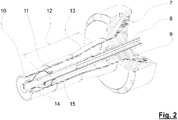
- the range of calibration is in FIG. 2 illustrated illustrated.
- FIG. 2 shows a part of the calibration station 3 in longitudinal section, in turn, the walls of the plastic profile 10 shown here by way of example can be seen in the form of a tube.
- a calibration tool 11 here in the form of a diameter-adjustable calibration sleeve, is shown schematically.
- the still pasty preformed plastic tube 7 passes from the tool 2 via the tube head and the nozzle 9 in this calibration 11. So this is pressed without the use of a conventional vacuum to the inner wall of the Kalibrierwerkmaschinectiones 11, ie the Kalibrierhülsees, for exact diameter definition, is inside the Tube 10 generates an overpressure.
- a plug 14 which is realized here by a flexible bellows 14, is arranged inside the tube 10.
- This flexible bellows 14 can be expanded by inflation or by filling with a fluid to the different pipe diameters and thus escape of the pressure can be prevented. As a result of this overpressure, the profile 10 is pressed against the inner wall of the calibration sleeve 11. It is also possible to keep a plug in the form of a drag mandrel with a chain or the like in its position inside the pipe.
- an external cooling is provided, which can be realized in the form of water spray nozzles, not shown. The use of a full bath is conceivable.
- the illustrated embodiment is preferred, in which the flexible bellows 14 is supplied via fluid lines 15. About this fluid lines 15 of the flexible bellows is widened so far that the interior of the profile is sealed and the space 13 between the bellows 14 and the nozzle 9 of the tool 2 can be pressurized to the plastic material to the inner walls of the calibration tool 11 press.
- the flexible bellows 14, which is arranged on a carrier tube 8, can be displaced via this in its entirety in the axial direction, so that the axial position 12 of the bellows relative to the nozzle 9 is variable. This ensures that the space 13 includes the region of the Kalibrierhülse 11 or not.
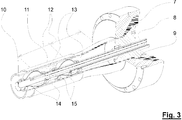
- FIG. 3 corresponds substantially to the embodiment of the FIG. 2 , in which case a further flexible bellows 14 is additionally arranged here.
- This further bellows can also be widened by means of the fluid line 15.
- two pressurizable chambers 13 are thus created. It can thus specifically targeted only the space between the two flexible bellows 14 are pressurized or the space 13 between the nozzle 9 and the first bellows 14 or both spaces.
Landscapes
- Engineering & Computer Science (AREA)
- Mechanical Engineering (AREA)
- Physics & Mathematics (AREA)
- Thermal Sciences (AREA)
- Extrusion Moulding Of Plastics Or The Like (AREA)
Description
- Die Erfindung betrifft ein Verfahren zur Herstellung von Kunststoffprofilen mit einem Extruder, einem sich in Produktionsrichtung an den Extruder anschließenden Rohrkopf und einer Kalibrierstation, in der das Kunststoffprofil an die Innenwandung eines Kalibrierwerkzeuges anlegbar ist.
- Bei den heute bekannten Kalibriersystemen wird in einer Kalibriervorrichtung durch Anlegen von einem Vakuum das zu kalibrierende Kunststoffrohr an die Innenwandung des Kalibrierwerkzeuges gesaugt. Hierbei sind diverse Probleme zu überwinden, deren Lösung meist komplizierte Vorrichtungen zur Folge haben. Durch das anliegende Vakuum ist eine ausreichende Abdichtung der Kalibrierstation gegenüber dem Umgebungsdruck erforderlich, was sowohl zu einer problematischen Einlauf- als auch einer Auslasssituation führt, da dieses Vakuumsystem mindestens an zwei Seiten offen sein muss, da das zu kalibrierende Rohr auf der einen Seite hinein und auf der anderen Seite hinaus geführt wird.
- Im Stand der Technik gibt es hinreichende Offenbarungen von Rohrextrusionsanlagen bei denen vorgeschlagen wird eine Kalibrierung über anlegen eines Druckes im Inneren des Rohres zu kalibrieren. So schlagen zum Beispiel die
WO 90/02644 A1 WO 2004/089605 A1 und dieWO 97/06940 A1 WO 97/10941 A1 GB 1 145 762 A - Aufgabe der vorliegenden Erfindung ist es daher, ein Kalibriersystem anzubieten, mittels dem diese Probleme überwunden werden bzw. überhaupt nicht auftreten können und damit die Vorrichtung einfacher baut.
- Die Lösung der Aufgabe ist in Verbindung mit dem Oberbegriff des Anspruches 1 dadurch gekennzeichnet, dass das Kunststoffprofil, während es das Kalibrierwerkzeug, bestehend aus mindestens einer Hülse und einem Balg, durchläuft, im Bereich des Kalibrierwerkzeuges mit Überdruck beaufschlagt wird, wobei der Überdruck mittels eines flexiblen und kühlbaren Balges im Inneren des Kunststoffprofils erzeugt wird, wobei zum Aufbau des Überdruckes im Kunststoffprofil der flexible Balg im Inneren des Kunststoffprofils soweit mit einem Fluid gefüllt wird, dass der erforderliche Überdruck in einem inneren Teilbereich des Kunststoffprofils erzeugt werden kann, wobei mindestens im Bereich mit Überdruck das Kunststoffprofil von innen zusätzlich gekühlt wird, wobei das Kalibrierwerkzeug im Querschnitt, insbesondere im Durchmesser, veränderbar ist, wobei das Kalibrierwerkzeug in Abhängigkeit des Massespaltes des Rohrkopfes oder umgekehrt verändert wird.
- Dieser Balg dehnt sich analog eines Luftballons gezielt aus, die Materialbeschaffenheit des flexiblen Balgs kann so gewählt werden, dass Teilbereiche des Balgs stärker als andere Bereiche gedehnt werden können und somit definiert nicht nur ein Kreisring, sondern auch ovale oder sonstige Profile abgebildet werden. Weiterhin bietet dieser flexible Balg die Möglichkeit, einerseits ihn selbst als auch die Innenseite des zu kalibrierenden Profils zu kühlen. Die Kunststoffmasse wird gegen das Kalibrierwerkzeug gepresst und somit definiert an diese angelegt.
- Der flexible Balg dichtet somit einen Innenbereich des zu kalibrierenden Rohres zwischen dem Balg und dem Rohrkopf ab, so dass dieser mit Überdruck beaufschlagt werden kann. Hierdurch wird erreicht, dass der Bereich zwischen Rohrkopf und Kalibrierwerkzeug weiter im Durchmesser als die Kalibrierhülse selbst aufgeweitet werden kann, wodurch sichergestellt wird, dass die Kunststoffmasse an der Innenwandung des Kalibrierwerkzeuges anliegt.
- Hierbei ist es ohne weiteres denkbar, das Kühlmedium gleichzeitig zum Aufweiten des flexiblen Balgs zu verwenden. Dies kann beispielsweise dadurch gelöst werden, dass ein Fluid, flüssig oder gasförmig, kalt oder warm, entlang eines Trägerrohres durch den Rohrkopf bis in den flexiblen Balg geleitet wird, diesen auf den nötigen Umfang erweitert und dann gezielt über im Balg eingebrachte Ventile das Fluid in den gewünschten Überdruckbereich entweichen lässt. Je nach gewähltem Fluid wird der flexible Balg selbst als auch das Innere des Kunststoffprofiles gekühlt.
- Das vorgeschlagene Verfahren eignet sich auch für Extruderlinien, bei denen unterschiedliche Profildurchmesser gefahren werden, so dass weiterbildungsgemäß vorgesehen ist, dass das Kalibrierwerkzeug im Querschnitt, insbesondere im Durchmesser, veränderbar ist. Durch den Einsatz des flexiblen Balgs ist keine Umrüstung erforderlich, da dieser auch bei verändertem Querschnitt ausreichend weit aufgedehnt werden kann.
- Durch die Änderung des Kalibrierwerkzeuges in Abhängigkeit des Massespaltes kann mit der Verstellung nur eines Parameters alle weiteren davon abhängigen Aggregate in der Extrusionslinie verändert werden.
- Es ist also weiterbildungsgemäß vorgesehen, dass das Fluid zunächst in das Innere des Balges gelangt und von diesem in den zu kühlenden Bereich des Kunststoffprofils eingebracht wird. Insbesondere bei der Verwendung von flüssigen Medien wird vorgeschlagen, dass das Fluid mit einem Ausgleichsbehälter in Verbindung steht, um bei plötzlich auftretenden Formänderungen des flexiblen Balges den vorherrschenden Druck schnellstmöglich abbauen bzw. kompensieren zu können.
- Fortbildungsgemäß ist vorgesehen, dass der Balg in seiner axialen Position relativ zum Kalibrierwerkzeug veränderbar ist. Hierdurch wird erreicht, den Bereich mit vorherrschendem Überdruck im Inneren des zu kalibrierenden Rohres gezielt zu wählen. Der Bereich kann somit nur vor dem Kalibrierwerkzeug, innerhalb des Kalibrierwerkzeuges liegen oder auch den Bereich des Kalibrierwerkzeuges mit einschließen, aber auch in Extrusionsrichtung betrachtet, sich hinter dem Kalibrierwerkzeug befinden.
- In den Zeichnungen ist schematisch ein Ausführungsbeispiel der Erfindung wiedergegeben.
- Fig. 1
- zeigt eine Extruderlinie und
- Fig. 2
- den Bereich der Kalibrierung im Detail,
- Fig. 3
- eine Alternative zu
Fig. 2 . - In der
Figur 1 ist eine Extruderlinie mit einem herkömmlichen Extruder 1 und einem sich anschließenden Werkzeug 2, in der Regel in Form eines Rohrkopfes, vorteilhafterweise auch mit verstellbarem Massespalt, gezeigt. Daran schließt sich eine Kalibrierstation 3 an. An diese Kalibrierstation 3 können sich weitere Nachfolgeeinrichtungen 4 wie weitere Sprühkalibrierstationen sowie Abzug 5, und Säge 6 etc. anschließen. Der Bereich der Kalibrierung ist inFigur 2 verdeutlicht dargestellt. -
Figur 2 zeigt einen Teil der Kalibrierstation 3 im Längsschnitt, wobei wiederum die Wandungen des hier beispielhaft dargestellten Kunststoffprofils 10 in Form eines Rohres zu sehen sind. Innerhalb der Kalibrierstation 3 ist ein Kalibrierwerkzeug 11, hier in Form einer im Durchmesser verstellbaren Kalibrierhülse, schematisch dargestellt. Das noch pastöse vorgeformte Kunststoffrohr 7 gelangt vom Werkzeug 2 über den Rohrkopf und die Düse 9 in diese Kalibrierhülse 11. Damit dieses ohne Verwendung eines üblichen Vakuums an die Innenwandung des Kalibrierwerkzeuges 11, sprich der Kalibrierhülse, zur exakten Durchmesserdefinierung gepresst wird, wird im Inneren des Rohres 10 ein Überdruck erzeugt. Um diesen Überdruck zu erzeugen ist im Inneren des Rohres 10 ein Stopfen 14 angeordnet, welcher hier durch einen flexiblen Balg 14 realisiert wird. Dieser flexible Balg 14 kann durch Aufblasen oder durch Füllen mit einem Fluid auf die unterschiedlichen Rohrdurchmesser aufgeweitet werden und somit ein Entweichen des Druckes verhindert werden. Durch diesen Überdruck wird das Profil 10 an die Innenwandung der Kalibrierhülse 11 gedrückt. Es ist auch möglich, einen Stopfen in Form eines Schleppdornes mit einer Kette oder ähnlichem in seiner Position im Rohrinneren zu halten. Innerhalb der Kalibrierstation, besonders im Bereich der Kalibrierhülse 11, ist eine Außenkühlung vorgesehen, die in Form von nicht dargestellten Wassersprühdüsen realisierbar ist. Auch die Verwendung eines Vollbades ist denkbar. In dem Bereich 13, in dem der Überdruck im Inneren des Rohres erzeugt wird, also zwischen dem Rohrkopf 9 und dem flexiblen Balg 14, ist vorgesehen, zusätzlich eine Innenkühlung anzubringen. Dies wird hier beispielsweise in Form von in diesen Bereich hineinragenden Hohlprofilen mit entsprechenden Sprühöffnungen ermöglicht. Um eine entsprechende Zirkulation im Inneren des Profils zu realisieren ist vorgesehen, an einem anderen Punkt innerhalb des Rohres die Flüssigkeit oder den Wasserdampf wieder abzusaugen und somit einen Kühlkreislauf zu ermöglichen. - Bevorzugt wird die dargestellte Ausführungsform, bei der der flexible Balg 14 über Fluidleitungen 15 versorgt wird. Über diese Fluidleitungen 15 wird der flexible Balg so weit aufgeweitet, dass das Innere des Profiles abgedichtet wird und der Raum 13 zwischen dem Balg 14 und der Düse 9 des Werkzeuges 2 mit Überdruck beaufschlagt werden kann, um das Kunststoffmaterial an die Innenwandungen des Kalibrierwerkzeuges 11 zu pressen. Der flexible Balg 14, der auf einem Trägerrohr 8 angeordnet ist, kann über dieses in Gänze in axialer Richtung verschoben werden, so dass die axiale Position 12 des Balges relativ zur Düse 9 veränderbar ist. Hierdurch wird erreicht, dass der Raum 13 den Bereich der Kalibrierhülse 11 mit beinhaltet oder nicht.
-
Figur 3 entspricht im Wesentlichen der Ausführungsform derFigur 2 , wobei hier zusätzlich ein weiterer flexibler Balg 14 angeordnet ist. Auch dieser weitere Balg kann mittels der Fluidleitung 15 aufgeweitet werden. Durch diese Doppelanordnung von zwei flexiblen Bälgen werden somit zwei mit Überdruck beaufschlagbare Räume 13 geschaffen. Es kann somit gezielt nur der Raum zwischen den beiden flexiblen Bälgen 14 mit Überdruck beaufschlagt werden oder auch der Raum 13 zwischen der Düse 9 und dem ersten Balg 14 oder auch beide Räume. Auch hier ist wiederum vorgesehen, über das Trägerrohr 8, an dem die beiden flexiblen Bälge 14 angeordnet sind, die axiale Position der Bälge 14 relativ zur Düse 9 zu verändern. - Besonders praktisch ist es, wenn alle zu verstellenden Parameter wie Durchmesser des zu extrudierenden Rohres und damit der Kalibrierung und in Folge die Aufweitung des flexiblen Balges über eine geeignete Steuerung automatisch gesteuert oder geregelt werden. Dies gilt natürlich analog für weitere hier nicht erwähnte Parameter.
- Im Bedarfsfall ist es auch denkbar, zur Intensivierung der Kühlung das gesamte Becken, in dem sich die Kalibrierung befindet, zu fluten und somit eine Außenkühlung umzusetzen.
- Zum Schutz des flexiblen Balgs wird vorgeschlagen, diesen mit einem gewickeltem Rohr, wie es aus der
DE 10 2004 052 972 bekannt ist, zu umgeben. Der Balg weitet dann das Rohr auf, welches wiederum die Kunststoffmasse gegen die Innenwandung der Kalibrierung drückt. Der flexible Balg ist so gegen Verschleiß und Hitze geschützt. -
- 1
- Extruder
- 2
- Werkzeug
- 3
- Kalibrierstation
- 4
- diverse Nachfolgeeinrichtungen
- 5
- Abzug
- 6
- Säge
- 7
- extrudierte Kunststoffmasse
- 8
- Trägerrohr
- 9
- Düse von 2
- 10
- Profil
- 11
- Kalibrierhülse
- 12
- axiale Position von 14
- 13
- Raum zwischen 9 und 14
- 14
- flexibler Balg
- 15
- Fluidleitung
Claims (4)
- Verfahren zur Herstellung von Kunststoffprofilen (10) mit
einem Extruder (1),
einem sich in Produktionsrichtung an den Extruder (1) anschließenden Rohrkopf (2) und
einer Kalibrierstation (3), in der das Kunststoffprofil (10) an die Innenwandung eines Kalibrierwerkzeuges (11) anlegbar ist,
das Kunststoffprofil (10), während es das Kalibrierwerkzeug bestehend aus mindestens einer Kalibrierhülse (11) und einem flexiblen und kühlbaren Balg (14), durchläuft, im Bereich des Kalibrierwerkzeuges mit Überdruck beaufschlagt wird,
wobei der Überdruck mittels des flexiblen und kühlbaren
Balges (14) im Inneren des Kunststoffprofils (10) erzeugt wird, wobei zum Aufbau des Überdruckes im Kunststoffprofil (10) der flexible Balg (14) im Inneren des Kunststoffprofils (10) soweit mit einem Fluid gefüllt wird, dass der erforderliche Überdruck in einem inneren Teilbereich des Kunststoffprofils (10) erzeugt werden kann, dadurch gekennzeichnet, dass mindestens im Bereich (13), in dem der Überdruck im Inneren des Kunststoffprofils (10) erzeugt wird, also zwischen dem Rohrkopf (9) und dem flexiblen und kühlbaren Balg (14), eine zusätzliche Innenkühlung vorgesehen ist, wobei das Kalibrierwerkzeug im Querschnitt, insbesondere im Durchmesser, veränderbar ist,
wobei das Kalibrierwerkzeug in Abhängigkeit des Massespaltes des Rohrkopfes (2) oder umgekehrt mit Hilfe einer Steuerung verändert wird. - Verfahren nach Anspruch 1, dadurch gekennzeichnet, dass das Fluid zunächst in das Innere des Balges (14) gelangt und von diesem in den zu kühlenden Bereich (13) des Kunststoffprofils (10) eingebracht wird.
- Verfahren nach mindestens einem der vorigen Ansprüche, dadurch gekennzeichnet, dass das Fluid mit einem Ausgleichsbehälter in Verbindung steht.
- Verfahren nach mindestens einem der vorigen Ansprüche, dadurch gekennzeichnet, dass der Balg (14) in seiner axialen Position relativ zum Kalibrierwerkzeug veränderbar ist.
Applications Claiming Priority (1)
| Application Number | Priority Date | Filing Date | Title |
|---|---|---|---|
| DE102008026682A DE102008026682B3 (de) | 2008-06-04 | 2008-06-04 | Verfahren und Vorrichtung zur Herstellung von Kunststoffprofilen |
Publications (2)
| Publication Number | Publication Date |
|---|---|
| EP2130662A1 EP2130662A1 (de) | 2009-12-09 |
| EP2130662B1 true EP2130662B1 (de) | 2017-07-12 |
Family
ID=41100703
Family Applications (1)
| Application Number | Title | Priority Date | Filing Date |
|---|---|---|---|
| EP09160977.6A Not-in-force EP2130662B1 (de) | 2008-06-04 | 2009-05-25 | Verfahren zur Herstellung von Kunststoffprofilen |
Country Status (2)
| Country | Link |
|---|---|
| EP (1) | EP2130662B1 (de) |
| DE (1) | DE102008026682B3 (de) |
Families Citing this family (2)
| Publication number | Priority date | Publication date | Assignee | Title |
|---|---|---|---|---|
| DE102010043791A1 (de) | 2010-11-11 | 2012-05-16 | Battenfeld-Cincinnati Germany Gmbh | Vorrichtung und Verfahren zum Führen und Formen eines extrudierten Kunststoffstranges |
| EP2926973B1 (de) | 2014-03-31 | 2021-07-21 | FITT S.p.A | Verfahren und Fertigungsstrasse für die Herstellung von festen Rohren |
Family Cites Families (14)
| Publication number | Priority date | Publication date | Assignee | Title |
|---|---|---|---|---|
| DE1156972B (de) * | 1959-05-06 | 1963-11-07 | Frieseke & Hoepfner Gmbh | Verschluss- und Abziehstopfen fuer Extruderanlage |
| FR91622E (fr) | 1965-06-19 | 1968-07-19 | Tubes stratifiés étanches | |
| DE2519705C2 (de) * | 1975-05-02 | 1982-03-18 | MFC Maschinenfabrik Chur AG, Chur | Vorrichtung zum Strangpressen von Rohren |
| DE2652641C2 (de) * | 1976-11-19 | 1978-12-14 | Reifenhaeuser Kg, 5210 Troisdorf | Einrichtung zur Innenkühlung von Kunststoffhohlprofilen |
| DD228212B1 (de) * | 1984-06-15 | 1988-02-24 | Bitterfeld Chemie | Verschlusselement zur kalibrierung von thermoplastischen, geschlossenen hohlprofilen |
| WO1990002644A1 (en) | 1988-09-15 | 1990-03-22 | Vinidex Tubemakers Pty. Limited | Method of pipe manufacture |
| AUPN485095A0 (en) | 1995-08-18 | 1995-09-07 | Uponor B.V. | Process control |
| BR9610557A (pt) | 1995-09-20 | 1999-12-21 | Uponor Bv | Produtos poliméricos orientados |
| FR2806956B1 (fr) * | 2000-03-29 | 2003-05-09 | Alphacan Sa | Procede et ligne de fabrication en continu de tubes en matiere plastique avec etirage bi-axial, et tube en matiere plastique obtenu |
| AT412626B (de) * | 2000-09-13 | 2005-05-25 | Greiner Extrusionstechnik Gmbh | Überwachungseinrichtung für eine formgebungsanlage |
| AU2003901596A0 (en) | 2003-04-08 | 2003-05-01 | Uponor Innovation Ab | Method and apparatus for control of plastics tube orientation process |
| DE102004052972B4 (de) | 2004-10-29 | 2010-10-28 | Battenfeld Extrusionstechnik Gmbh | Vorrichtung und Verfahren zum Führen und Formen eines extrudierten Kunststoffstranges |
| DE102005006474A1 (de) * | 2005-02-12 | 2006-08-17 | Kiefel Extrusion Gmbh | Verfahren und Vorrichtung zur Herstellung von Blasfolien |
| DE102006051103A1 (de) * | 2006-10-25 | 2008-04-30 | Inoex Gmbh | Vorrichtung zum Extrudieren von Hohlsträngen |
-
2008
- 2008-06-04 DE DE102008026682A patent/DE102008026682B3/de not_active Expired - Fee Related
-
2009
- 2009-05-25 EP EP09160977.6A patent/EP2130662B1/de not_active Not-in-force
Also Published As
| Publication number | Publication date |
|---|---|
| DE102008026682B3 (de) | 2009-11-19 |
| EP2130662A1 (de) | 2009-12-09 |
Similar Documents
| Publication | Publication Date | Title |
|---|---|---|
| DE102009012694A1 (de) | Ausbuchtungsbildungsverfahren und Ausbuchtungsbildungsvorrichtung | |
| EP2613922B1 (de) | Kalibriereinrichtung für einen blasfolienschlauch | |
| DE69524438T2 (de) | Füll- und druckaufschlagseinrichtung | |
| EP0546335A1 (de) | Vorrichtung zum Begasen von Flüssigkeiten | |
| EP2900394B1 (de) | Deoxidation von schräggewalzten hohlblöcken | |
| DE1954381A1 (de) | Einrichtung zum Herstellen eines Querrillen aufweisenden Kunststoffrohres | |
| DE102010061840A1 (de) | Kolben-Zylindereinheit als schaltbarer Stufen-Zylinder | |
| DE102008026682B3 (de) | Verfahren und Vorrichtung zur Herstellung von Kunststoffprofilen | |
| EP2712691B1 (de) | Vorrichtung und Verfahren zur Sekundarkühlung in einer Gießanlage | |
| EP2496399B1 (de) | Vorrichtung verfahren zum abdichten eines kühltankes für ein extrudiertes kunststoffprofil | |
| DE3913334A1 (de) | Vorrichtung fuer die zerstaeubung von fluessigkeit oder fuer die zerteilung von gas in kleine blasen | |
| DE2263683A1 (de) | Strangpressvorrichtung zum herstellen von rohren aus thermoplastischem material | |
| EP2291274A1 (de) | Strangpressvorrichtung zur herstellung von kunststoffrohren und eine flexible dichtung für diese vorrichtung | |
| DE102004008620B3 (de) | Kalibrierkorb für eine Kalibrierstation | |
| DE2756039A1 (de) | Vorrichtung zum verformen und kalibrieren eines vermittels des blas-spritzgussverfahrens hergestellten kunststoffschlauchs | |
| DE10335518A1 (de) | Vorrichtung zur Herstellung eines doppelwandigen thermoplastischen Rohrs mit einer Rohrmuffe | |
| DE10153159B4 (de) | Ventil | |
| DE102022119880B3 (de) | Vorrichtung und Verwendung einer Vorrichtung sowie Anlage und Verfahren zum Herstellen eines mit flüssigem Füllgut befüllten Behälters aus einem thermisch konditionierten Vorformling | |
| DE948869C (de) | Strangpresse mit im Pressstempel axial beweglichem, durch eine Fluessigkeit gekuehltem Dorn | |
| DE102016215977A1 (de) | Düsenreihenanordnung und Düsenfeld zum Einbau in Rollenspalte zwischen zwei Strangführungsrollen | |
| DE102021128341B4 (de) | Verfahren zum Formen eines in eine Form einer Form- und Füllstation eingesetzten Vorformlings zu einem Behälter und Befüllen des sich formenden Behälters mit flüssigem Füllgut | |
| DE10338348B3 (de) | Aufweitlanze | |
| DE102024118724A1 (de) | Vorrichtung und Anlage zum Herstellen mindestens eines Behälters, Behälterherstellungsmaschine und Verfahren zum Steuern mindestens einer Behälterherstellungsmaschine | |
| DE10237632A1 (de) | Temperierbare Walze und Verfahren zu ihrem Betrieb | |
| WO2024074439A1 (de) | Verfahren und vorrichtung zum herstellen eines mit flüssigem füllgut befüllten behälters aus einem thermisch konditionierten vorformling |
Legal Events
| Date | Code | Title | Description |
|---|---|---|---|
| PUAI | Public reference made under article 153(3) epc to a published international application that has entered the european phase |
Free format text: ORIGINAL CODE: 0009012 |
|
| AK | Designated contracting states |
Kind code of ref document: A1 Designated state(s): AT BE BG CH CY CZ DE DK EE ES FI FR GB GR HR HU IE IS IT LI LT LU LV MC MK MT NL NO PL PT RO SE SI SK TR |
|
| 17P | Request for examination filed |
Effective date: 20100609 |
|
| 17Q | First examination report despatched |
Effective date: 20100702 |
|
| RAP1 | Party data changed (applicant data changed or rights of an application transferred) |
Owner name: BATTENFELD-CINCINNATI GERMANY GMBH |
|
| RAP1 | Party data changed (applicant data changed or rights of an application transferred) |
Owner name: BATTENFELD-CINCINNATI GERMANY GMBH |
|
| GRAP | Despatch of communication of intention to grant a patent |
Free format text: ORIGINAL CODE: EPIDOSNIGR1 |
|
| RIC1 | Information provided on ipc code assigned before grant |
Ipc: B29C 47/20 20060101ALN20170112BHEP Ipc: B29C 47/90 20060101ALI20170112BHEP Ipc: B29C 47/88 20060101AFI20170112BHEP Ipc: B29C 47/92 20060101ALI20170112BHEP |
|
| INTG | Intention to grant announced |
Effective date: 20170127 |
|
| GRAS | Grant fee paid |
Free format text: ORIGINAL CODE: EPIDOSNIGR3 |
|
| GRAA | (expected) grant |
Free format text: ORIGINAL CODE: 0009210 |
|
| AK | Designated contracting states |
Kind code of ref document: B1 Designated state(s): AT BE BG CH CY CZ DE DK EE ES FI FR GB GR HR HU IE IS IT LI LT LU LV MC MK MT NL NO PL PT RO SE SI SK TR |
|
| REG | Reference to a national code |
Ref country code: GB Ref legal event code: FG4D Free format text: NOT ENGLISH |
|
| REG | Reference to a national code |
Ref country code: CH Ref legal event code: EP |
|
| REG | Reference to a national code |
Ref country code: AT Ref legal event code: REF Ref document number: 907915 Country of ref document: AT Kind code of ref document: T Effective date: 20170715 |
|
| REG | Reference to a national code |
Ref country code: IE Ref legal event code: FG4D Free format text: LANGUAGE OF EP DOCUMENT: GERMAN |
|
| REG | Reference to a national code |
Ref country code: DE Ref legal event code: R096 Ref document number: 502009014144 Country of ref document: DE |
|
| REG | Reference to a national code |
Ref country code: NL Ref legal event code: MP Effective date: 20170712 |
|
| REG | Reference to a national code |
Ref country code: LT Ref legal event code: MG4D |
|
| PG25 | Lapsed in a contracting state [announced via postgrant information from national office to epo] |
Ref country code: FI Free format text: LAPSE BECAUSE OF FAILURE TO SUBMIT A TRANSLATION OF THE DESCRIPTION OR TO PAY THE FEE WITHIN THE PRESCRIBED TIME-LIMIT Effective date: 20170712 Ref country code: NO Free format text: LAPSE BECAUSE OF FAILURE TO SUBMIT A TRANSLATION OF THE DESCRIPTION OR TO PAY THE FEE WITHIN THE PRESCRIBED TIME-LIMIT Effective date: 20171012 Ref country code: LT Free format text: LAPSE BECAUSE OF FAILURE TO SUBMIT A TRANSLATION OF THE DESCRIPTION OR TO PAY THE FEE WITHIN THE PRESCRIBED TIME-LIMIT Effective date: 20170712 Ref country code: SE Free format text: LAPSE BECAUSE OF FAILURE TO SUBMIT A TRANSLATION OF THE DESCRIPTION OR TO PAY THE FEE WITHIN THE PRESCRIBED TIME-LIMIT Effective date: 20170712 Ref country code: HR Free format text: LAPSE BECAUSE OF FAILURE TO SUBMIT A TRANSLATION OF THE DESCRIPTION OR TO PAY THE FEE WITHIN THE PRESCRIBED TIME-LIMIT Effective date: 20170712 Ref country code: NL Free format text: LAPSE BECAUSE OF FAILURE TO SUBMIT A TRANSLATION OF THE DESCRIPTION OR TO PAY THE FEE WITHIN THE PRESCRIBED TIME-LIMIT Effective date: 20170712 |
|
| PG25 | Lapsed in a contracting state [announced via postgrant information from national office to epo] |
Ref country code: IS Free format text: LAPSE BECAUSE OF FAILURE TO SUBMIT A TRANSLATION OF THE DESCRIPTION OR TO PAY THE FEE WITHIN THE PRESCRIBED TIME-LIMIT Effective date: 20171112 Ref country code: LV Free format text: LAPSE BECAUSE OF FAILURE TO SUBMIT A TRANSLATION OF THE DESCRIPTION OR TO PAY THE FEE WITHIN THE PRESCRIBED TIME-LIMIT Effective date: 20170712 Ref country code: PL Free format text: LAPSE BECAUSE OF FAILURE TO SUBMIT A TRANSLATION OF THE DESCRIPTION OR TO PAY THE FEE WITHIN THE PRESCRIBED TIME-LIMIT Effective date: 20170712 Ref country code: BG Free format text: LAPSE BECAUSE OF FAILURE TO SUBMIT A TRANSLATION OF THE DESCRIPTION OR TO PAY THE FEE WITHIN THE PRESCRIBED TIME-LIMIT Effective date: 20171012 Ref country code: ES Free format text: LAPSE BECAUSE OF FAILURE TO SUBMIT A TRANSLATION OF THE DESCRIPTION OR TO PAY THE FEE WITHIN THE PRESCRIBED TIME-LIMIT Effective date: 20170712 Ref country code: GR Free format text: LAPSE BECAUSE OF FAILURE TO SUBMIT A TRANSLATION OF THE DESCRIPTION OR TO PAY THE FEE WITHIN THE PRESCRIBED TIME-LIMIT Effective date: 20171013 |
|
| REG | Reference to a national code |
Ref country code: DE Ref legal event code: R097 Ref document number: 502009014144 Country of ref document: DE |
|
| PG25 | Lapsed in a contracting state [announced via postgrant information from national office to epo] |
Ref country code: CZ Free format text: LAPSE BECAUSE OF FAILURE TO SUBMIT A TRANSLATION OF THE DESCRIPTION OR TO PAY THE FEE WITHIN THE PRESCRIBED TIME-LIMIT Effective date: 20170712 Ref country code: RO Free format text: LAPSE BECAUSE OF FAILURE TO SUBMIT A TRANSLATION OF THE DESCRIPTION OR TO PAY THE FEE WITHIN THE PRESCRIBED TIME-LIMIT Effective date: 20170712 Ref country code: DK Free format text: LAPSE BECAUSE OF FAILURE TO SUBMIT A TRANSLATION OF THE DESCRIPTION OR TO PAY THE FEE WITHIN THE PRESCRIBED TIME-LIMIT Effective date: 20170712 |
|
| PLBE | No opposition filed within time limit |
Free format text: ORIGINAL CODE: 0009261 |
|
| STAA | Information on the status of an ep patent application or granted ep patent |
Free format text: STATUS: NO OPPOSITION FILED WITHIN TIME LIMIT |
|
| PG25 | Lapsed in a contracting state [announced via postgrant information from national office to epo] |
Ref country code: SK Free format text: LAPSE BECAUSE OF FAILURE TO SUBMIT A TRANSLATION OF THE DESCRIPTION OR TO PAY THE FEE WITHIN THE PRESCRIBED TIME-LIMIT Effective date: 20170712 Ref country code: EE Free format text: LAPSE BECAUSE OF FAILURE TO SUBMIT A TRANSLATION OF THE DESCRIPTION OR TO PAY THE FEE WITHIN THE PRESCRIBED TIME-LIMIT Effective date: 20170712 |
|
| 26N | No opposition filed |
Effective date: 20180413 |
|
| PG25 | Lapsed in a contracting state [announced via postgrant information from national office to epo] |
Ref country code: SI Free format text: LAPSE BECAUSE OF FAILURE TO SUBMIT A TRANSLATION OF THE DESCRIPTION OR TO PAY THE FEE WITHIN THE PRESCRIBED TIME-LIMIT Effective date: 20170712 |
|
| PG25 | Lapsed in a contracting state [announced via postgrant information from national office to epo] |
Ref country code: MT Free format text: LAPSE BECAUSE OF FAILURE TO SUBMIT A TRANSLATION OF THE DESCRIPTION OR TO PAY THE FEE WITHIN THE PRESCRIBED TIME-LIMIT Effective date: 20170712 |
|
| REG | Reference to a national code |
Ref country code: DE Ref legal event code: R079 Ref document number: 502009014144 Country of ref document: DE Free format text: PREVIOUS MAIN CLASS: B29C0047880000 Ipc: B29C0048880000 |
|
| REG | Reference to a national code |
Ref country code: CH Ref legal event code: PL |
|
| GBPC | Gb: european patent ceased through non-payment of renewal fee |
Effective date: 20180525 |
|
| REG | Reference to a national code |
Ref country code: BE Ref legal event code: MM Effective date: 20180531 |
|
| PG25 | Lapsed in a contracting state [announced via postgrant information from national office to epo] |
Ref country code: MC Free format text: LAPSE BECAUSE OF FAILURE TO SUBMIT A TRANSLATION OF THE DESCRIPTION OR TO PAY THE FEE WITHIN THE PRESCRIBED TIME-LIMIT Effective date: 20170712 |
|
| REG | Reference to a national code |
Ref country code: IE Ref legal event code: MM4A |
|
| PG25 | Lapsed in a contracting state [announced via postgrant information from national office to epo] |
Ref country code: LI Free format text: LAPSE BECAUSE OF NON-PAYMENT OF DUE FEES Effective date: 20180531 Ref country code: CH Free format text: LAPSE BECAUSE OF NON-PAYMENT OF DUE FEES Effective date: 20180531 |
|
| PG25 | Lapsed in a contracting state [announced via postgrant information from national office to epo] |
Ref country code: LU Free format text: LAPSE BECAUSE OF NON-PAYMENT OF DUE FEES Effective date: 20180525 |
|
| PG25 | Lapsed in a contracting state [announced via postgrant information from national office to epo] |
Ref country code: IE Free format text: LAPSE BECAUSE OF NON-PAYMENT OF DUE FEES Effective date: 20180525 Ref country code: FR Free format text: LAPSE BECAUSE OF NON-PAYMENT OF DUE FEES Effective date: 20180531 Ref country code: IT Free format text: LAPSE BECAUSE OF NON-PAYMENT OF DUE FEES Effective date: 20180525 Ref country code: GB Free format text: LAPSE BECAUSE OF NON-PAYMENT OF DUE FEES Effective date: 20180525 |
|
| PG25 | Lapsed in a contracting state [announced via postgrant information from national office to epo] |
Ref country code: BE Free format text: LAPSE BECAUSE OF NON-PAYMENT OF DUE FEES Effective date: 20180531 |
|
| REG | Reference to a national code |
Ref country code: AT Ref legal event code: MM01 Ref document number: 907915 Country of ref document: AT Kind code of ref document: T Effective date: 20180525 |
|
| PG25 | Lapsed in a contracting state [announced via postgrant information from national office to epo] |
Ref country code: AT Free format text: LAPSE BECAUSE OF NON-PAYMENT OF DUE FEES Effective date: 20180525 |
|
| PG25 | Lapsed in a contracting state [announced via postgrant information from national office to epo] |
Ref country code: TR Free format text: LAPSE BECAUSE OF FAILURE TO SUBMIT A TRANSLATION OF THE DESCRIPTION OR TO PAY THE FEE WITHIN THE PRESCRIBED TIME-LIMIT Effective date: 20170712 |
|
| PG25 | Lapsed in a contracting state [announced via postgrant information from national office to epo] |
Ref country code: HU Free format text: LAPSE BECAUSE OF FAILURE TO SUBMIT A TRANSLATION OF THE DESCRIPTION OR TO PAY THE FEE WITHIN THE PRESCRIBED TIME-LIMIT; INVALID AB INITIO Effective date: 20090525 Ref country code: PT Free format text: LAPSE BECAUSE OF FAILURE TO SUBMIT A TRANSLATION OF THE DESCRIPTION OR TO PAY THE FEE WITHIN THE PRESCRIBED TIME-LIMIT Effective date: 20170712 |
|
| PG25 | Lapsed in a contracting state [announced via postgrant information from national office to epo] |
Ref country code: MK Free format text: LAPSE BECAUSE OF NON-PAYMENT OF DUE FEES Effective date: 20170712 Ref country code: CY Free format text: LAPSE BECAUSE OF FAILURE TO SUBMIT A TRANSLATION OF THE DESCRIPTION OR TO PAY THE FEE WITHIN THE PRESCRIBED TIME-LIMIT Effective date: 20170712 |
|
| PGFP | Annual fee paid to national office [announced via postgrant information from national office to epo] |
Ref country code: DE Payment date: 20200531 Year of fee payment: 12 |
|
| REG | Reference to a national code |
Ref country code: DE Ref legal event code: R119 Ref document number: 502009014144 Country of ref document: DE |
|
| PG25 | Lapsed in a contracting state [announced via postgrant information from national office to epo] |
Ref country code: DE Free format text: LAPSE BECAUSE OF NON-PAYMENT OF DUE FEES Effective date: 20211201 |