EP2130663A1 - Einstellbarer Abdeckrahmen für eine Thermoformmaschine mit besagtem Rahmen - Google Patents
Einstellbarer Abdeckrahmen für eine Thermoformmaschine mit besagtem Rahmen Download PDFInfo
- Publication number
- EP2130663A1 EP2130663A1 EP08425398A EP08425398A EP2130663A1 EP 2130663 A1 EP2130663 A1 EP 2130663A1 EP 08425398 A EP08425398 A EP 08425398A EP 08425398 A EP08425398 A EP 08425398A EP 2130663 A1 EP2130663 A1 EP 2130663A1
- Authority
- EP
- European Patent Office
- Prior art keywords
- moveable element
- moveable
- designed
- frame
- frame according
- Prior art date
- Legal status (The legal status is an assumption and is not a legal conclusion. Google has not performed a legal analysis and makes no representation as to the accuracy of the status listed.)
- Granted
Links
Images


Classifications
-
- B—PERFORMING OPERATIONS; TRANSPORTING
- B29—WORKING OF PLASTICS; WORKING OF SUBSTANCES IN A PLASTIC STATE IN GENERAL
- B29C—SHAPING OR JOINING OF PLASTICS; SHAPING OF MATERIAL IN A PLASTIC STATE, NOT OTHERWISE PROVIDED FOR; AFTER-TREATMENT OF THE SHAPED PRODUCTS, e.g. REPAIRING
- B29C33/00—Moulds or cores; Details thereof or accessories therefor
- B29C33/12—Moulds or cores; Details thereof or accessories therefor with incorporated means for positioning inserts, e.g. labels
-
- B—PERFORMING OPERATIONS; TRANSPORTING
- B29—WORKING OF PLASTICS; WORKING OF SUBSTANCES IN A PLASTIC STATE IN GENERAL
- B29C—SHAPING OR JOINING OF PLASTICS; SHAPING OF MATERIAL IN A PLASTIC STATE, NOT OTHERWISE PROVIDED FOR; AFTER-TREATMENT OF THE SHAPED PRODUCTS, e.g. REPAIRING
- B29C49/00—Blow-moulding, i.e. blowing a preform or parison to a desired shape within a mould; Apparatus therefor
- B29C49/42—Component parts, details or accessories; Auxiliary operations
- B29C49/4236—Drive means
-
- B—PERFORMING OPERATIONS; TRANSPORTING
- B29—WORKING OF PLASTICS; WORKING OF SUBSTANCES IN A PLASTIC STATE IN GENERAL
- B29C—SHAPING OR JOINING OF PLASTICS; SHAPING OF MATERIAL IN A PLASTIC STATE, NOT OTHERWISE PROVIDED FOR; AFTER-TREATMENT OF THE SHAPED PRODUCTS, e.g. REPAIRING
- B29C33/00—Moulds or cores; Details thereof or accessories therefor
- B29C33/30—Mounting, exchanging or centering
- B29C33/306—Exchangeable mould parts, e.g. cassette moulds, mould inserts
-
- B—PERFORMING OPERATIONS; TRANSPORTING
- B29—WORKING OF PLASTICS; WORKING OF SUBSTANCES IN A PLASTIC STATE IN GENERAL
- B29C—SHAPING OR JOINING OF PLASTICS; SHAPING OF MATERIAL IN A PLASTIC STATE, NOT OTHERWISE PROVIDED FOR; AFTER-TREATMENT OF THE SHAPED PRODUCTS, e.g. REPAIRING
- B29C51/00—Shaping by thermoforming, i.e. shaping sheets or sheet like preforms after heating, e.g. shaping sheets in matched moulds or by deep-drawing; Apparatus therefor
- B29C51/08—Deep drawing or matched-mould forming, i.e. using mechanical means only
-
- B—PERFORMING OPERATIONS; TRANSPORTING
- B29—WORKING OF PLASTICS; WORKING OF SUBSTANCES IN A PLASTIC STATE IN GENERAL
- B29C—SHAPING OR JOINING OF PLASTICS; SHAPING OF MATERIAL IN A PLASTIC STATE, NOT OTHERWISE PROVIDED FOR; AFTER-TREATMENT OF THE SHAPED PRODUCTS, e.g. REPAIRING
- B29C51/00—Shaping by thermoforming, i.e. shaping sheets or sheet like preforms after heating, e.g. shaping sheets in matched moulds or by deep-drawing; Apparatus therefor
- B29C51/26—Component parts, details or accessories; Auxiliary operations
- B29C51/261—Handling means, e.g. transfer means, feeding means
- B29C51/262—Clamping means for the sheets, e.g. clamping frames
-
- B—PERFORMING OPERATIONS; TRANSPORTING
- B29—WORKING OF PLASTICS; WORKING OF SUBSTANCES IN A PLASTIC STATE IN GENERAL
- B29C—SHAPING OR JOINING OF PLASTICS; SHAPING OF MATERIAL IN A PLASTIC STATE, NOT OTHERWISE PROVIDED FOR; AFTER-TREATMENT OF THE SHAPED PRODUCTS, e.g. REPAIRING
- B29C2791/00—Shaping characteristics in general
- B29C2791/004—Shaping under special conditions
- B29C2791/006—Using vacuum
Definitions
- This invention relates to an adjustable cover frame for a thermoforming machine and to a thermoforming machine comprising said frame.
- this invention relates to a cover frame according to the preamble of the attached Claim 1 and to a thermoforming machine which includes a frame of the abovementioned type.
- thermoforming machines are their ability to accommodate, inside the structure of the machine itself, moulds of variable dimensions in a range of predetermined sizes.
- the dimensions of the moulds are proportionally correlated to those of the parts to be produced, in other words they are correlated to the size of the product to be manufactured by the thermoforming process.
- thermoforming is a process suitable for medium or small batches, and therefore requires the replacement of moulds with some frequency.
- thermoforming box of which is necessarily designed to be suitable for accommodating the largest mould that will be used in that machine.
- One of the main steps in this reconfiguration is adapting the room present in the thermoforming box to the actual dimensions of the mould intended to be used to make the product.
- a cover frame having an inner window is usually fitted to the top of the thermoforming box.
- the cover frame is thus superimposed on the opening of the box, so that the inner window is able to accommodate the mould onto which the sheet of plastic material, to which the thermoforming process will be applied, must be positioned.
- the sheet is selected to have a dimension such as to reproduce the shape of the product which is to be thermoformed, bearing in mind the addition of a region around the outer edge which will be subsequently removed.
- the outer region of the sheet has the function of acting as a contact surface, ensuring airtightness during the thermo forming process.
- thermoforming machine This step in the reconfiguration of a conventional thermoforming machine is therefore highly complex and difficult, being time consuming and demanding accurate work.
- this operation requires replacing the cover frame whenever the mould which is to be used in the thermoforming process is changed, and this happens somewhat frequently because production batches are medium or small runs.
- adjustable cover frames of known type use a plurality of plates which are connected in such a way that they can slide relative to each other by attachment systems which also act as guides and are essentially mechanical in nature (for example they use connections defined by shape such as dovetail or mortise and tenon type attachments), which connect these plates permanently together.
- attachment systems which also act as guides and are essentially mechanical in nature (for example they use connections defined by shape such as dovetail or mortise and tenon type attachments), which connect these plates permanently together.
- To produce these guided attachment systems requires machining of high accuracy and some technical difficulty.
- Adjustable cover frames of the type indicated above exhibit numerous drawbacks, due in particular to the type of guided attachment systems which are used to connect the edges of the adjustment plates.
- dovetail and similar shape-based attachments have the drawback of using hollow and solid regions to provide conjoined sliding surfaces between the plates. These hollow regions provide a receptacle for dirt and scrap, which can cause problems in the normal operation of the thermoforming frame.
- thermoforming machine capable of solving this and other drawbacks of the prior art, and which at the same time can be produced simply and inexpensively.
- thermoforming machine of improved type It is another object of the present invention to provide a thermoforming machine of improved type.
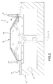
- reference F indicates an illustrative embodiment of an adjustable cover frame for a thermoforming machine T.
- the cover frame F comprises four moveable elements or plates 11, 12, 13 and 14 that form an essentially rectangular annular arrangement, in which:
- Each of these plates 11, 12, 13, 14 has its own main body 21, 22, 23, 24 of advantageously essentially parallelepiped shape.
- the main bodies 21, 22, 23 and 24 of the plates 11, 12, 13 and 14 are made advantageously in aluminium or light aluminium alloys.
- each of these plates 11, 12, 13, 14 has a respective transverse edge portion 31, 32, 33, 34 located on a short side of the perimeter of the main body 21, 22, 23, 24, and a respective longitudinal edge portion 41, 42, 43, 44 situated on a long side of the perimeter of this main body 21, 22, 23, 24.
- transverse edge portions 31, 32, 33, 34 and the longitudinal edge portions 41, 42, 43, 44 project upwards in the same direction relative to the plane defined by the respective main bodies 21, 22, 23, 24.
- the respective transverse edge portion 31, 32, 33, 34 of each of the plates 11, 12, 13, 14 is adjacent to the respective longitudinal edge portion 42, 43, 44, 41 of the next plate 12, 13, 14, 11.
- the transverse edge portions 31, 32, 33, 34 and the longitudinal edge portions 41, 42, 43, 44 are preferably respectively separate parallelepiped units connected in a stable manner to the respective main bodies 21, 22, 23, 24, for example by screws as visible in figures 5, 5a and 6 .
- the longitudinal edge portions 41, 42, 43, 44 are located in the inward perimeter region of the rectangular ring formed by the plates 11, 12, 13, 14 and define an inner window W of adjustable dimensions.
- FIG. 5 shows advantageous features of the transverse edge portion 32 and of the longitudinal edge portion 43.
- the transverse edge portion 32 and the longitudinal edge portion 43 comprise a lateral overhang 62 and a raised margin 73, respectively.
- the lateral overhang 62 and the raised margin 73 run the entire length of the transverse edge portion 32 and the entire length of the longitudinal edge portion 43, respectively.
- the lateral overhang 62 is intended to be located above the raised margin 73.
- this arrangement means that the transverse edge portions 31, 32, 33, 34 are guided as they slide along the top of the subsequent adjacent longitudinal edge portions 42, 43, 44, 41.
- the contact area between these edge portions is reduced, thereby reducing the friction generated during the movement of the plates 11, 12, 13, 14.
- the lateral overhang could be on the longitudinal edge portion 43, while the raised margin could be on the transverse edge portion 32.
- the cover frame F is designed to be mounted on the thermoforming box B of a thermoforming machine T.
- the thermoforming box B has an upward opening A and the plates 11, 12, 13, 14 are designed to at least partly cover the abovementioned opening A.
- Each longitudinal edge portion 41, 42, 43, 44 is preferably made of a magnetizable ferromagnetic material.
- Each transverse edge portion 31, 32, 33, 34 encloses a respective electromagnetic device indicated schematically as a whole by the broken lines 51, 52, 53 and 54 ( figures 3 and 4 ).
- Each electromagnetic device 51, 52, 53 and 54 comprises a respective permanent magnet (not shown) which normally magnetizes the longitudinal edge portions 41, 42, 43, 44. In this way, when the electromagnetic devices 51, 52, 53 and 54 are de-energized, they attract the ferromagnetic material of the subsequent adjacent longitudinal edge portions 42, 43, 44, 41. This condition is illustrated by the transverse edge portion 32 and the longitudinal edge portion 42 in figure 5 .
- An alternative method is to use a known type of electromagnet as an electromagnetic device: when energized by electric current this attracts and locks together the adjacent transverse and longitudinal edge portions. In this method, when the electromagnet is de-energized, the adjacent plates are not attracted or locked.
- Each electromagnetic device 51, 52, 53, 54 comprises its own solenoid (also not shown) which is designed to be energized selectively by an electric current to generate a magnetic field which opposes the magnetic field of the associated permanent magnet (not shown) contained in the corresponding transverse edge portion 31, 32, 33, 34.
- solenoids when the solenoids are energized, they cancel out the magnetic force of attraction of the permanent magnet, thereby releasing the corresponding transverse edge portion 31, 32, 33, 34 of the subsequent adjacent longitudinal edge portion 42, 43, 44, 41.
- thermoforming machine T In an initial condition, when the thermoforming machine T is disabled and not running, the cover frame F is in the locked configuration described above.
- the cover frame F is initially placed in a first adjustment configuration.
- the second and fourth electromagnetic devices 52, 54 are energized and release the third and first longitudinal edge portions 43, 41, respectively, from the second and fourth transverse edge portions 32, 34.
- the first and third electromagnetic devices 51, 53 meanwhile remain de-energized.
- first and second plates 11, 12 remain magnetically attracted, forming a first L-shaped conjoined unit 100.
- the third and fourth plates 13, 14 also remain magnetically attracted, forming a second L-shaped conjoined unit 200.
- the fourth and first plates 14, 11 are not attracted to each other, nor are the second and third plates 12, 13.
- this first adjustment configuration there is a separation of the frame in the first and second units 100, 200 due to a slight parting of the second and fourth transverse edge portions 32, 34 from the third and first longitudinal edge portions 43, 41 resulting from the interruption of the magnetic attraction.
- the first and second units 100, 200 can then be shifted relative to each other in a first direction of adjustment X-X approximately parallel to the second and fourth transverse edge portions 32, 34 to adjust a first dimension x of the window W.
- the second and fourth electromagnetic devices 52, 54 are de-energized and the plates 11, 12, 13, 14 return to the locked configuration.
- this minimizes the contact area between the transverse edge portions 32, 34 and the associated longitudinal edge portions 43, 41 and, during the movement in the X-X direction, they are not necessarily in contact with each other. This arrangement reduces friction and the need for lubrication.
- the cover frame F is then changed from the locked configuration to a second adjustment configuration.
- the first and third electromagnetic devices 51, 53 are energized and release the second and fourth longitudinal edge portions 42, 44 from the first and third transverse edge portions 31, 33, respectively.
- the second and fourth electromagnetic devices 52, 54 which had been energized in the first adjustment configuration, this time remain de-energized.
- the second and third plates 12, 13 remain magnetically attracted, forming a third L-shaped conjoined unit 300.
- the fourth and first plates 14, 11 also remain magnetically attracted, forming a fourth L-shaped conjoined unit 400.
- the first and second plates 11, 12 are no longer attracted to each other, nor are the third and fourth plates 13, 14.
- the third and fourth units 300, 400 move away from each other, because the first and third transverse edge portions 31, 33 separate from the second and fourth longitudinal edge portions 42, 44 due to the absence of magnetic attraction.
- the third and fourth units 300, 400 can then be shifted relative to each other in a second direction of adjustment Y-Y parallel to the first and third transverse edge portions 31, 33, thereby adjusting a second dimension y of the window W, orthogonal to the first dimension x.
- the first and third electromagnetic devices 51, 53 are de-energized and the plates 11, 12, 13, 14 returned to the locked configuration.
- the adjacent plates 11, 12, 13, 14 in the locked configuration can easily be aligned with the centre of the opening A of the box B by moving the entire frame C as a monolithic whole.
- the air seal can be provided by mechanical means only, without the need to interpose variously profiled gaskets between the gaps present between the abovementioned plates.
- the window W can be adjusted by carrying out the first and second adjustment configurations of registration described above in such a way that the dimensions x, y are adapted to the dimensions of a mould M to be used.
- the window W is then aligned with the opening A by shifting the cover frame F (when in the locked configuration) and the thermoforming process can begin.
- a sheet of plastic material S suitably preheated by suitable heating devices (not shown) is clamped between a clamp frame C and the cover frame F. In this situation sheet S is preferably blown first to make the surface with which this sheet S will be laid on the mould M, convex.
- the sheet S is applied against the mould M inside the thermoforming box B.
- suitable pumping devices (not shown) generate a depression or vacuum in the direction indicated by the arrows V to "suck" the sheet S towards the opening A so that it clings to the surface of the mould M.
- the upper faces of the longitudinal edges 41, 42, 43, 44 of the plates 11, 12, 13, 14 are advantageously provided with seals of a type known per se (such as gaskets) which will seal the region between the clamp frame C, to which the sheet S is applied, and the cover frame F.
- seals of a type known per se such as gaskets
- the electromagnetic devices 51, 52, 53, 54 can adopt a plurality of different adjustment configurations, in which they alternately release a respective individual plate from the other plates, which remain attached to each other. In this way an individual released plate can be shifted, adjusting the position and dimension of one side of the inner window W.
- the electromagnetic devices 51, 52, 53, 54 can then be energized: then the first plate 11 will be free to move relative to the other three plates 12, 13, 14 which remain joined together.
- the second and first electromagnetic devices 52, 51 can then be energized, and then it will be the second plate 12 to be released from the remaining group of plates 13, 14, 11 and so on.
- the individual plates can initially all be released from each other and then shifted independently of each other into the desired arrangement. Once in position they can be returned to the locked configuration.
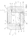
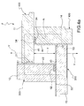
- FIGS 7 and 8 show the cover plate 11 resting on the thermoforming box B.
- the cover plate has a pair of channels 200, 202 along the top and oriented lengthwise in a direction perpendicular to the length of the cover plate 11.
- the channels 200, 202 are parallel to the Y-Y direction of registration.
- the channels 200, 202 also accommodate a respective pair of externally threaded worms 204, 206 which rotate about their longitudinal axis when driven as will be described in detail later.
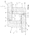
- the main body 21 has a T-section longitudinal channel 208 running the full length of the cover plate 11.
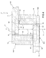
- first and second internally threaded nut blocks 210, 212 ending in respective first and second upper projections 214, 216 are connected around the first and second worms 204, 206 by means of recirculating balls.
- the upper projections 214 and 216 are inserted into the narrow leg 208a of the longitudinal channel 208.
- the top face of the main body 21 has first and second openings 218 and 220 located above the longitudinal channel 208 and communicating with its enlarged head 208b.
- the plate 11 is moved so that the first and second openings 218 and 220 are coaxial with the first and second upper projections 214 and 216.
- First and second plugs 222 and 224 are then inserted through the first and second openings 218 and 220, so that they rest on the first and second upper projections 214 and 216, and are then screwed down onto these. Consequently the first and second plugs 222 and 224 are fixed to the first and second blocks 210, 212.
- the transverse dimension of the first and second blocks 222 and 224 is advantageously greater than the transverse dimension of the first and second upper projections 214 and 216 respectively (and also of the narrow leg 208a of the longitudinal channel 208), but less than the transverse dimension of the enlarged head 208b of the longitudinal channel 208.
- the first and second plugs 222 and 224 thus bear on the respective shoulder surfaces formed by the enlarged head 208b. This gives the plate 11 an "anti-tip" function when moved.
- Another advantage of using the plugs 222 and 224 is that they improve the guided sliding movement of the plate 11 relative to the thermoforming box B.
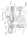
- the thermoforming box B includes an electric motor 226 that turns a drive shaft 228, which meshes with a transmission chain 230 which in turn acts on first and second drive portions 232, 234 of the first and second worms 204, 206. Therefore, when an operator operates the electric motor 226 in either direction of rotation, the first and second worms 204 and 206 will, through the first and second blocks 210, 212, move the plate 11 in the Y-Y direction towards or away from the centre of the thermoforming box B.
- the thermoforming box B also includes first and second protective strips 236, 238 designed to cover the abovementioned channels 200, 202.
- the width of the protective strip 236 and 238 is equal to or greater than the width of the channels 200, 202.
- These first and second protective strips 236 and 238 are connected at respective first ends to the first and second block 210, 212 and at the opposite respective ends to the thermoforming box B by a winding device of a type known per se.
- a single strip of sufficient dimensions to cover both channels 200 and 202 could be installed in place of a pair of strips 236 and 238.
- FIG 6 shows an alternative embodiment of the locking system associated with the transverse edge portion 32.
- the features of this embodiment are of course also reproduced in the other transverse edge portions 31, 33, 34.
- the electromagnetic device of the transverse edge portion 32 has been replaced with a mechanical locking device 102 shown in figure 6 in an attached and locked condition.
- This device 102 comprises a profile in the shape of an overturned U 112 which straddles the respective transverse edge portion 32 and the adjacent longitudinal edge portion 43.
- the profile 112 is connected to the transverse edge portion 32 by its head 82 which projects upward and is shaped like a T.
- the narrow neck of the head 82 is housed with play in a transverse direction relative to the plate 12.
- the mechanical locking device 102 also includes elastic means (not shown) tending to push a piston 122 out against the transverse edge portion 32, pressing it against the adjacent longitudinal edge portion 43. This locks mechanically together the two adjacent plates 12 and 13, which are in the attached condition when the locking device 102 is de-energized.
- the frame F in this second embodiment is also normally in the locked configuration.
- the mechanical locking device 102 also includes pneumatic actuating means of a type known per se (not shown) which, in response to an operator command, can be activated to return the piston 32 from the extended position to a retracted position (not shown). In this way the transverse edge portion 32 and the longitudinal edge portion 43 can be separated afterwards to allow relative sliding between the plates 12 and 13, as in the embodiment described earlier.
- the relative sliding movement between the plates 12 and 13 is advantageously guided by the profile 112 which straddles the transverse edge portion 32 and the succeeding adjacent longitudinal edge portion 43.
- the type of releasable attachment between the transverse and longitudinal edge portions of the plates can also be provided by using mechanical locking members to attach by hydraulic, electromechanical, electrical, piezoelectrical and such-like means besides those shown in the embodiments described and illustrated here.
- the second embodiment uses, for the locking devices, a different, less preferred operation in which, when they are de-energized, they set the associated transverse and longitudinal edge portions in the unattached condition, in which case, when the locking devices are on, the associated transverse and longitudinal edge portions are set in the attached and locked condition.
Landscapes
- Engineering & Computer Science (AREA)
- Mechanical Engineering (AREA)
- Manufacturing & Machinery (AREA)
- Lining Or Joining Of Plastics Or The Like (AREA)
- Refrigerator Housings (AREA)
Priority Applications (2)
| Application Number | Priority Date | Filing Date | Title |
|---|---|---|---|
| ES08425398.8T ES2439464T3 (es) | 2008-06-05 | 2008-06-05 | Máquina de termoformado con un bastidor de tapa ajustable |
| EP08425398.8A EP2130663B8 (de) | 2008-06-05 | 2008-06-05 | Thermoformmaschine mit einem einstellbaren Abdeckrahmen |
Applications Claiming Priority (1)
| Application Number | Priority Date | Filing Date | Title |
|---|---|---|---|
| EP08425398.8A EP2130663B8 (de) | 2008-06-05 | 2008-06-05 | Thermoformmaschine mit einem einstellbaren Abdeckrahmen |
Publications (3)
| Publication Number | Publication Date |
|---|---|
| EP2130663A1 true EP2130663A1 (de) | 2009-12-09 |
| EP2130663B1 EP2130663B1 (de) | 2013-08-14 |
| EP2130663B8 EP2130663B8 (de) | 2013-09-25 |
Family
ID=39916281
Family Applications (1)
| Application Number | Title | Priority Date | Filing Date |
|---|---|---|---|
| EP08425398.8A Active EP2130663B8 (de) | 2008-06-05 | 2008-06-05 | Thermoformmaschine mit einem einstellbaren Abdeckrahmen |
Country Status (2)
| Country | Link |
|---|---|
| EP (1) | EP2130663B8 (de) |
| ES (1) | ES2439464T3 (de) |
Cited By (5)
| Publication number | Priority date | Publication date | Assignee | Title |
|---|---|---|---|---|
| EP2522484A3 (de) * | 2011-05-11 | 2014-11-05 | Krones AG | Vorrichtung zum Umformen von Kunststoffvorformlingen zu Kunststoffbehältnissen mit magnetisch betätigter Verriegelung |
| EP3031595A4 (de) * | 2013-08-05 | 2017-03-08 | Fu-se Vacuum Forming Co., Ltd. | Verfahren zur herstellung eines teilvakuums mit partieller überlagerung von dekorfolien |
| CN111890665A (zh) * | 2020-07-17 | 2020-11-06 | 广州海鸥住宅工业股份有限公司 | 有可靠密封及装夹结构的用于防水盘生产的正压成型设备 |
| CN116551968A (zh) * | 2023-05-23 | 2023-08-08 | 苏州鑫铭智新材料有限公司 | 吸塑盘成型机 |
| US20230302746A1 (en) * | 2020-08-31 | 2023-09-28 | Tusas- Turk Havacilik Ve Uzay Sanayii Anonim Sirketi | A composite part production system |
Citations (7)
| Publication number | Priority date | Publication date | Assignee | Title |
|---|---|---|---|---|
| AT223371B (de) * | 1960-03-21 | 1962-09-10 | Adolf Ing Hoeger | Spannrahmen für Folien oder Platten, insbesondere aus Kunststoff |
| DE2427311A1 (de) * | 1974-06-06 | 1975-12-18 | Frank & Co L E | Mehreckrahmen, insbesondere rechteckrahmen zur herstellung von kunststoffschalen |
| GB1467425A (en) * | 1974-06-04 | 1977-03-16 | Mounteney D | Vacuum-forming machines |
| EP0692365A1 (de) | 1994-07-14 | 1996-01-17 | Maschinenfabrik Georg Geiss | Abdeckplatte für Vakuumformmaschinen |
| DE19941065C1 (de) * | 1999-08-28 | 2000-12-07 | Illig Maschinenbau Adolf | Heizstation zum Beheizen von Platten aus thermoplastischem Kunststoff |
| US20020079611A1 (en) * | 2000-12-27 | 2002-06-27 | Ellison Thomas M. | Process and apparatus for preparing a molded article |
| EP1876011A2 (de) * | 2006-07-07 | 2008-01-09 | Forma S.R.L. | Teleskopisch einstellbare Abdeckungsvorrichtung für den Vakuumkasten von Warmformungsmaschinen |
-
2008
- 2008-06-05 ES ES08425398.8T patent/ES2439464T3/es active Active
- 2008-06-05 EP EP08425398.8A patent/EP2130663B8/de active Active
Patent Citations (7)
| Publication number | Priority date | Publication date | Assignee | Title |
|---|---|---|---|---|
| AT223371B (de) * | 1960-03-21 | 1962-09-10 | Adolf Ing Hoeger | Spannrahmen für Folien oder Platten, insbesondere aus Kunststoff |
| GB1467425A (en) * | 1974-06-04 | 1977-03-16 | Mounteney D | Vacuum-forming machines |
| DE2427311A1 (de) * | 1974-06-06 | 1975-12-18 | Frank & Co L E | Mehreckrahmen, insbesondere rechteckrahmen zur herstellung von kunststoffschalen |
| EP0692365A1 (de) | 1994-07-14 | 1996-01-17 | Maschinenfabrik Georg Geiss | Abdeckplatte für Vakuumformmaschinen |
| DE19941065C1 (de) * | 1999-08-28 | 2000-12-07 | Illig Maschinenbau Adolf | Heizstation zum Beheizen von Platten aus thermoplastischem Kunststoff |
| US20020079611A1 (en) * | 2000-12-27 | 2002-06-27 | Ellison Thomas M. | Process and apparatus for preparing a molded article |
| EP1876011A2 (de) * | 2006-07-07 | 2008-01-09 | Forma S.R.L. | Teleskopisch einstellbare Abdeckungsvorrichtung für den Vakuumkasten von Warmformungsmaschinen |
Non-Patent Citations (1)
| Title |
|---|
| DATABASE WPI Week 197602, Derwent World Patents Index; AN 1976-02198X * |
Cited By (7)
| Publication number | Priority date | Publication date | Assignee | Title |
|---|---|---|---|---|
| EP2522484A3 (de) * | 2011-05-11 | 2014-11-05 | Krones AG | Vorrichtung zum Umformen von Kunststoffvorformlingen zu Kunststoffbehältnissen mit magnetisch betätigter Verriegelung |
| US9067354B2 (en) | 2011-05-11 | 2015-06-30 | Krones Ag | Apparatus for the shaping of plastics material pre-forms into plastics material containers with magnetically actuated locking |
| EP3031595A4 (de) * | 2013-08-05 | 2017-03-08 | Fu-se Vacuum Forming Co., Ltd. | Verfahren zur herstellung eines teilvakuums mit partieller überlagerung von dekorfolien |
| CN111890665A (zh) * | 2020-07-17 | 2020-11-06 | 广州海鸥住宅工业股份有限公司 | 有可靠密封及装夹结构的用于防水盘生产的正压成型设备 |
| US20230302746A1 (en) * | 2020-08-31 | 2023-09-28 | Tusas- Turk Havacilik Ve Uzay Sanayii Anonim Sirketi | A composite part production system |
| US12508785B2 (en) * | 2020-08-31 | 2025-12-30 | Tusas—Turk Havacilik Ve Uzay Sanayii Anonim Sirketi | Composite part production system |
| CN116551968A (zh) * | 2023-05-23 | 2023-08-08 | 苏州鑫铭智新材料有限公司 | 吸塑盘成型机 |
Also Published As
| Publication number | Publication date |
|---|---|
| EP2130663B8 (de) | 2013-09-25 |
| EP2130663B1 (de) | 2013-08-14 |
| ES2439464T3 (es) | 2014-01-23 |
Similar Documents
| Publication | Publication Date | Title |
|---|---|---|
| EP2130663B1 (de) | Thermoformmaschine mit einem einstellbaren Abdeckrahmen | |
| US10512965B2 (en) | Device and method for mutual separation of two workpiece components of a plate-like workpiece | |
| KR101203825B1 (ko) | 자기 체이스 및 그래픽 아트 다이 어셈블리 | |
| US5338045A (en) | Device for application of mechanical and magnetic forces to a fixture | |
| KR100626275B1 (ko) | 자동 정압 밀봉 접근 도어 | |
| EP0560847A1 (de) | Vakuumplatte | |
| RU2711518C1 (ru) | Машина для обработки листов с устройством для распределения газа и/или вакуума и способ управления устройством для распределения газа и/или вакуума | |
| CN110789063B (zh) | 模具更换装置 | |
| US9682485B2 (en) | Lifter cups with at least one channel and concentric slits | |
| KR102413543B1 (ko) | 마그넷 척 | |
| KR20080113424A (ko) | 사출성형기 | |
| US9777846B2 (en) | Relating to gate valves | |
| KR910007249B1 (ko) | 맞물림 장치 | |
| KR100659746B1 (ko) | 진공 처리 장치 | |
| EP3608056B1 (de) | Schleifmaschine zum schleifen von platten aus holz, metall oder ähnlichen stoffen | |
| WO1997010465A1 (en) | Armature assembly support pallet | |
| KR102534804B1 (ko) | 로봇 암의 병렬 그리퍼 | |
| US8671990B2 (en) | Vacuum valve apparatus and method | |
| EP2897771B1 (de) | Pressstempel zur herstellung von fliesen und dergleichen und verfahren zur entnahme von einem dünnen platte eines pressstempels | |
| CN111819072B (zh) | 用于粉末压机的压制设备以及工具更换系统 | |
| KR101621561B1 (ko) | 다이 이젝터 | |
| US12023771B2 (en) | Device for holding in position a product to be processed and a method | |
| CN215590298U (zh) | 打印平台及打印设备 | |
| US10351283B2 (en) | Magnetically operated sealing bar assembly for packaging machines | |
| EP3590875B1 (de) | Saugvorrichtung zum halten und/oder transportieren von objekten mit unterschiedlichen formaten |
Legal Events
| Date | Code | Title | Description |
|---|---|---|---|
| PUAI | Public reference made under article 153(3) epc to a published international application that has entered the european phase |
Free format text: ORIGINAL CODE: 0009012 |
|
| AK | Designated contracting states |
Kind code of ref document: A1 Designated state(s): AT BE BG CH CY CZ DE DK EE ES FI FR GB GR HR HU IE IS IT LI LT LU LV MC MT NL NO PL PT RO SE SI SK TR |
|
| AX | Request for extension of the european patent |
Extension state: AL BA MK RS |
|
| 17P | Request for examination filed |
Effective date: 20100603 |
|
| AKX | Designation fees paid |
Designated state(s): AT BE BG CH CY CZ DE DK EE ES FI FR GB GR HR HU IE IS IT LI LT LU LV MC MT NL NO PL PT RO SE SI SK TR |
|
| RIC1 | Information provided on ipc code assigned before grant |
Ipc: B29C 33/12 20060101ALN20121213BHEP Ipc: B29C 51/26 20060101AFI20121213BHEP Ipc: B29C 33/30 20060101ALN20121213BHEP Ipc: B29C 51/08 20060101ALI20121213BHEP |
|
| GRAP | Despatch of communication of intention to grant a patent |
Free format text: ORIGINAL CODE: EPIDOSNIGR1 |
|
| GRAS | Grant fee paid |
Free format text: ORIGINAL CODE: EPIDOSNIGR3 |
|
| GRAA | (expected) grant |
Free format text: ORIGINAL CODE: 0009210 |
|
| AK | Designated contracting states |
Kind code of ref document: B1 Designated state(s): AT BE BG CH CY CZ DE DK EE ES FI FR GB GR HR HU IE IS IT LI LT LU LV MC MT NL NO PL PT RO SE SI SK TR |
|
| REG | Reference to a national code |
Ref country code: GB Ref legal event code: FG4D |
|
| REG | Reference to a national code |
Ref country code: CH Ref legal event code: EP Ref country code: AT Ref legal event code: REF Ref document number: 626539 Country of ref document: AT Kind code of ref document: T Effective date: 20130815 |
|
| RAP2 | Party data changed (patent owner data changed or rights of a patent transferred) |
Owner name: PARCO S.R.L. |
|
| RIN2 | Information on inventor provided after grant (corrected) |
Inventor name: DI DIO LEONARDO Inventor name: DAL CERO PASQUALINO |
|
| REG | Reference to a national code |
Ref country code: IE Ref legal event code: FG4D |
|
| REG | Reference to a national code |
Ref country code: DE Ref legal event code: R081 Ref document number: 602008026733 Country of ref document: DE Owner name: COMI S.P.A., CISERANO, IT Free format text: FORMER OWNER: PARCO S.R.L., SAN GILLIO, IT |
|
| REG | Reference to a national code |
Ref country code: DE Ref legal event code: R096 Ref document number: 602008026733 Country of ref document: DE Effective date: 20131010 |
|
| REG | Reference to a national code |
Ref country code: NL Ref legal event code: VDEP Effective date: 20130814 |
|
| REG | Reference to a national code |
Ref country code: ES Ref legal event code: FG2A Ref document number: 2439464 Country of ref document: ES Kind code of ref document: T3 Effective date: 20140123 |
|
| REG | Reference to a national code |
Ref country code: LT Ref legal event code: MG4D |
|
| PG25 | Lapsed in a contracting state [announced via postgrant information from national office to epo] |
Ref country code: CY Free format text: LAPSE BECAUSE OF FAILURE TO SUBMIT A TRANSLATION OF THE DESCRIPTION OR TO PAY THE FEE WITHIN THE PRESCRIBED TIME-LIMIT Effective date: 20130814 Ref country code: HR Free format text: LAPSE BECAUSE OF FAILURE TO SUBMIT A TRANSLATION OF THE DESCRIPTION OR TO PAY THE FEE WITHIN THE PRESCRIBED TIME-LIMIT Effective date: 20130814 Ref country code: LT Free format text: LAPSE BECAUSE OF FAILURE TO SUBMIT A TRANSLATION OF THE DESCRIPTION OR TO PAY THE FEE WITHIN THE PRESCRIBED TIME-LIMIT Effective date: 20130814 Ref country code: NO Free format text: LAPSE BECAUSE OF FAILURE TO SUBMIT A TRANSLATION OF THE DESCRIPTION OR TO PAY THE FEE WITHIN THE PRESCRIBED TIME-LIMIT Effective date: 20131114 Ref country code: PT Free format text: LAPSE BECAUSE OF FAILURE TO SUBMIT A TRANSLATION OF THE DESCRIPTION OR TO PAY THE FEE WITHIN THE PRESCRIBED TIME-LIMIT Effective date: 20131216 Ref country code: SE Free format text: LAPSE BECAUSE OF FAILURE TO SUBMIT A TRANSLATION OF THE DESCRIPTION OR TO PAY THE FEE WITHIN THE PRESCRIBED TIME-LIMIT Effective date: 20130814 Ref country code: IS Free format text: LAPSE BECAUSE OF FAILURE TO SUBMIT A TRANSLATION OF THE DESCRIPTION OR TO PAY THE FEE WITHIN THE PRESCRIBED TIME-LIMIT Effective date: 20131214 |
|
| PG25 | Lapsed in a contracting state [announced via postgrant information from national office to epo] |
Ref country code: SI Free format text: LAPSE BECAUSE OF FAILURE TO SUBMIT A TRANSLATION OF THE DESCRIPTION OR TO PAY THE FEE WITHIN THE PRESCRIBED TIME-LIMIT Effective date: 20130814 Ref country code: LV Free format text: LAPSE BECAUSE OF FAILURE TO SUBMIT A TRANSLATION OF THE DESCRIPTION OR TO PAY THE FEE WITHIN THE PRESCRIBED TIME-LIMIT Effective date: 20130814 Ref country code: FI Free format text: LAPSE BECAUSE OF FAILURE TO SUBMIT A TRANSLATION OF THE DESCRIPTION OR TO PAY THE FEE WITHIN THE PRESCRIBED TIME-LIMIT Effective date: 20130814 Ref country code: GR Free format text: LAPSE BECAUSE OF FAILURE TO SUBMIT A TRANSLATION OF THE DESCRIPTION OR TO PAY THE FEE WITHIN THE PRESCRIBED TIME-LIMIT Effective date: 20131115 Ref country code: BE Free format text: LAPSE BECAUSE OF FAILURE TO SUBMIT A TRANSLATION OF THE DESCRIPTION OR TO PAY THE FEE WITHIN THE PRESCRIBED TIME-LIMIT Effective date: 20130814 Ref country code: PL Free format text: LAPSE BECAUSE OF FAILURE TO SUBMIT A TRANSLATION OF THE DESCRIPTION OR TO PAY THE FEE WITHIN THE PRESCRIBED TIME-LIMIT Effective date: 20130814 |
|
| PG25 | Lapsed in a contracting state [announced via postgrant information from national office to epo] |
Ref country code: CZ Free format text: LAPSE BECAUSE OF FAILURE TO SUBMIT A TRANSLATION OF THE DESCRIPTION OR TO PAY THE FEE WITHIN THE PRESCRIBED TIME-LIMIT Effective date: 20130814 Ref country code: SK Free format text: LAPSE BECAUSE OF FAILURE TO SUBMIT A TRANSLATION OF THE DESCRIPTION OR TO PAY THE FEE WITHIN THE PRESCRIBED TIME-LIMIT Effective date: 20130814 Ref country code: RO Free format text: LAPSE BECAUSE OF FAILURE TO SUBMIT A TRANSLATION OF THE DESCRIPTION OR TO PAY THE FEE WITHIN THE PRESCRIBED TIME-LIMIT Effective date: 20130814 Ref country code: NL Free format text: LAPSE BECAUSE OF FAILURE TO SUBMIT A TRANSLATION OF THE DESCRIPTION OR TO PAY THE FEE WITHIN THE PRESCRIBED TIME-LIMIT Effective date: 20130814 Ref country code: EE Free format text: LAPSE BECAUSE OF FAILURE TO SUBMIT A TRANSLATION OF THE DESCRIPTION OR TO PAY THE FEE WITHIN THE PRESCRIBED TIME-LIMIT Effective date: 20130814 Ref country code: DK Free format text: LAPSE BECAUSE OF FAILURE TO SUBMIT A TRANSLATION OF THE DESCRIPTION OR TO PAY THE FEE WITHIN THE PRESCRIBED TIME-LIMIT Effective date: 20130814 |
|
| PLBE | No opposition filed within time limit |
Free format text: ORIGINAL CODE: 0009261 |
|
| STAA | Information on the status of an ep patent application or granted ep patent |
Free format text: STATUS: NO OPPOSITION FILED WITHIN TIME LIMIT |
|
| 26N | No opposition filed |
Effective date: 20140515 |
|
| REG | Reference to a national code |
Ref country code: DE Ref legal event code: R097 Ref document number: 602008026733 Country of ref document: DE Effective date: 20140515 |
|
| PGFP | Annual fee paid to national office [announced via postgrant information from national office to epo] |
Ref country code: AT Payment date: 20140630 Year of fee payment: 7 |
|
| PGFP | Annual fee paid to national office [announced via postgrant information from national office to epo] |
Ref country code: ES Payment date: 20140715 Year of fee payment: 7 |
|
| PG25 | Lapsed in a contracting state [announced via postgrant information from national office to epo] |
Ref country code: LU Free format text: LAPSE BECAUSE OF FAILURE TO SUBMIT A TRANSLATION OF THE DESCRIPTION OR TO PAY THE FEE WITHIN THE PRESCRIBED TIME-LIMIT Effective date: 20140605 Ref country code: MC Free format text: LAPSE BECAUSE OF FAILURE TO SUBMIT A TRANSLATION OF THE DESCRIPTION OR TO PAY THE FEE WITHIN THE PRESCRIBED TIME-LIMIT Effective date: 20130814 |
|
| REG | Reference to a national code |
Ref country code: CH Ref legal event code: PL |
|
| REG | Reference to a national code |
Ref country code: IE Ref legal event code: MM4A |
|
| PG25 | Lapsed in a contracting state [announced via postgrant information from national office to epo] |
Ref country code: IE Free format text: LAPSE BECAUSE OF NON-PAYMENT OF DUE FEES Effective date: 20140605 Ref country code: CH Free format text: LAPSE BECAUSE OF NON-PAYMENT OF DUE FEES Effective date: 20140630 Ref country code: LI Free format text: LAPSE BECAUSE OF NON-PAYMENT OF DUE FEES Effective date: 20140630 |
|
| REG | Reference to a national code |
Ref country code: AT Ref legal event code: MM01 Ref document number: 626539 Country of ref document: AT Kind code of ref document: T Effective date: 20150605 |
|
| PG25 | Lapsed in a contracting state [announced via postgrant information from national office to epo] |
Ref country code: MT Free format text: LAPSE BECAUSE OF FAILURE TO SUBMIT A TRANSLATION OF THE DESCRIPTION OR TO PAY THE FEE WITHIN THE PRESCRIBED TIME-LIMIT Effective date: 20130814 |
|
| PG25 | Lapsed in a contracting state [announced via postgrant information from national office to epo] |
Ref country code: BG Free format text: LAPSE BECAUSE OF FAILURE TO SUBMIT A TRANSLATION OF THE DESCRIPTION OR TO PAY THE FEE WITHIN THE PRESCRIBED TIME-LIMIT Effective date: 20130814 Ref country code: AT Free format text: LAPSE BECAUSE OF NON-PAYMENT OF DUE FEES Effective date: 20150605 |
|
| REG | Reference to a national code |
Ref country code: FR Ref legal event code: PLFP Year of fee payment: 9 |
|
| REG | Reference to a national code |
Ref country code: ES Ref legal event code: FD2A Effective date: 20160727 |
|
| PG25 | Lapsed in a contracting state [announced via postgrant information from national office to epo] |
Ref country code: TR Free format text: LAPSE BECAUSE OF FAILURE TO SUBMIT A TRANSLATION OF THE DESCRIPTION OR TO PAY THE FEE WITHIN THE PRESCRIBED TIME-LIMIT Effective date: 20130814 Ref country code: HU Free format text: LAPSE BECAUSE OF FAILURE TO SUBMIT A TRANSLATION OF THE DESCRIPTION OR TO PAY THE FEE WITHIN THE PRESCRIBED TIME-LIMIT; INVALID AB INITIO Effective date: 20080605 |
|
| PG25 | Lapsed in a contracting state [announced via postgrant information from national office to epo] |
Ref country code: ES Free format text: LAPSE BECAUSE OF NON-PAYMENT OF DUE FEES Effective date: 20150606 |
|
| REG | Reference to a national code |
Ref country code: DE Ref legal event code: R081 Ref document number: 602008026733 Country of ref document: DE Owner name: COMI S.P.A., CISERANO, IT Free format text: FORMER OWNER: PARCO S.R.L., PIANEZZA, IT |
|
| REG | Reference to a national code |
Ref country code: GB Ref legal event code: 732E Free format text: REGISTERED BETWEEN 20170309 AND 20170315 |
|
| REG | Reference to a national code |
Ref country code: FR Ref legal event code: PLFP Year of fee payment: 10 |
|
| REG | Reference to a national code |
Ref country code: FR Ref legal event code: TP Owner name: COMI S.P.A., IT Effective date: 20170622 |
|
| REG | Reference to a national code |
Ref country code: FR Ref legal event code: PLFP Year of fee payment: 11 |
|
| PGFP | Annual fee paid to national office [announced via postgrant information from national office to epo] |
Ref country code: FR Payment date: 20191031 Year of fee payment: 13 |
|
| PG25 | Lapsed in a contracting state [announced via postgrant information from national office to epo] |
Ref country code: FR Free format text: LAPSE BECAUSE OF NON-PAYMENT OF DUE FEES Effective date: 20210630 |
|
| PGFP | Annual fee paid to national office [announced via postgrant information from national office to epo] |
Ref country code: DE Payment date: 20250630 Year of fee payment: 18 |
|
| PGFP | Annual fee paid to national office [announced via postgrant information from national office to epo] |
Ref country code: IT Payment date: 20250624 Year of fee payment: 18 |
|
| PGFP | Annual fee paid to national office [announced via postgrant information from national office to epo] |
Ref country code: GB Payment date: 20250722 Year of fee payment: 18 |