EP2130683B1 - Verbinder mit variabler Größe - Google Patents
Verbinder mit variabler Größe Download PDFInfo
- Publication number
- EP2130683B1 EP2130683B1 EP20090161554 EP09161554A EP2130683B1 EP 2130683 B1 EP2130683 B1 EP 2130683B1 EP 20090161554 EP20090161554 EP 20090161554 EP 09161554 A EP09161554 A EP 09161554A EP 2130683 B1 EP2130683 B1 EP 2130683B1
- Authority
- EP
- European Patent Office
- Prior art keywords
- wall
- binder
- bottom wall
- binder according
- defining
- Prior art date
- Legal status (The legal status is an assumption and is not a legal conclusion. Google has not performed a legal analysis and makes no representation as to the accuracy of the status listed.)
- Not-in-force
Links
- 239000011230 binding agent Substances 0.000 title claims description 70
- 239000000463 material Substances 0.000 claims description 16
- 230000003313 weakening effect Effects 0.000 claims description 6
- 230000001747 exhibiting effect Effects 0.000 claims description 5
- 238000012986 modification Methods 0.000 claims description 3
- 230000004048 modification Effects 0.000 claims description 3
- 230000002441 reversible effect Effects 0.000 claims 1
- 239000000123 paper Substances 0.000 description 3
- 238000003780 insertion Methods 0.000 description 2
- 230000037431 insertion Effects 0.000 description 2
- 230000006978 adaptation Effects 0.000 description 1
- 239000000853 adhesive Substances 0.000 description 1
- 230000001070 adhesive effect Effects 0.000 description 1
- 238000005452 bending Methods 0.000 description 1
- 230000008878 coupling Effects 0.000 description 1
- 238000010168 coupling process Methods 0.000 description 1
- 238000005859 coupling reaction Methods 0.000 description 1
- 230000003247 decreasing effect Effects 0.000 description 1
- 230000002093 peripheral effect Effects 0.000 description 1
- 238000004080 punching Methods 0.000 description 1
Images


Classifications
-
- B—PERFORMING OPERATIONS; TRANSPORTING
- B42—BOOKBINDING; ALBUMS; FILES; SPECIAL PRINTED MATTER
- B42F—SHEETS TEMPORARILY ATTACHED TOGETHER; FILING APPLIANCES; FILE CARDS; INDEXING
- B42F7/00—Filing appliances without fastening means
- B42F7/04—Covers with retention means
-
- B—PERFORMING OPERATIONS; TRANSPORTING
- B42—BOOKBINDING; ALBUMS; FILES; SPECIAL PRINTED MATTER
- B42F—SHEETS TEMPORARILY ATTACHED TOGETHER; FILING APPLIANCES; FILE CARDS; INDEXING
- B42F13/00—Filing appliances with means for engaging perforations or slots
- B42F13/38—Expansible cover splines or spines
-
- B—PERFORMING OPERATIONS; TRANSPORTING
- B42—BOOKBINDING; ALBUMS; FILES; SPECIAL PRINTED MATTER
- B42P—INDEXING SCHEME RELATING TO BOOKS, FILING APPLIANCES OR THE LIKE
- B42P2241/00—Parts, details or accessories for books or filing appliances
- B42P2241/02—Fasteners; Closures
- B42P2241/04—Band- or strip-like fasteners, e.g. tie strings
Definitions
- the object of the present invention is a binder, and in particular a binder of the type so/called "folder" used for filing documents and suitable for exhibiting a variable outer size based on the amount of documents contained therein.
- Variable size binders are known, defined by a rough shape of flexible cardboard suitably folded for defining a box shaped container as one substantially described in FR 2 082 000 .
- the rough shape exhibits a central square or rectangular wall suitable for defining a bottom of the binder, and four wings arranged at the sides of the central wall for defining as many side walls cross the bottom wall.
- One of the four wings exhibits a larger size for defining a top wall of the binder as well and for overlapping at least partly on the opposite wing so as to completely enclose the space within the binder.
- the top wall and the opposite wing can also be connected to one another by press buttons or by strings to tie.
- this type of binder is scarcely adaptable to variable amounts of documents.
- the side walls take a reduced thickness while an excessive surface of the top wall is created, which must be folded more around the opposite wing. This creates a greater difficulty for closing the binder and may make it impossible to close it by the above buttons or strings due to the lack of alignment between the top wall and the opposite wing.
- the greater folding of the top wall may lead the latter to be easily subject to risks of damages or even cracks.
- the side walls take a large thickness while a reduced or even insufficient overlapping is created between the top wall and the opposite wing.
- the insufficient overlapping may leave a part of the underlying documents exposed.
- the lack of alignment between the top wall and the opposite wing may make the reciprocal connection by the buttons or strings difficult, if not impossible.
- the binders of the prior art therefore are not very suitable for receiving an amount of documents differing from a precise predetermined value, exhibiting a considerable inconvenience of use related above all to the impossibility of properly closing the binder and having the latter take a configuration suitable for being inserted in an archive, for example on a shelf.
- Such binder presents an extensibile panel, defined by a poket, for varying surface extension to adapt the overall size of the binder to the size of the documents contained therein.
- variable capacity folder or wallet is disclosed in GB 2 406 076 .
- the disclosed folder comprises sliding joint between juxtaposed panels which form opposite pocket sides.
- a binder having an unfolded front sheet and a rear sheet with a folded over edge along the binding side is disclosed in DE 197 35 383 .
- the technical task of the present invention is to solve the problems found in the prior art by providing a variable size binder capable of solving the problems mentioned above.
- the object of the present invention is to provide a variable size binder which should exhibit a high convenience of use.
- a further object of the present invention is to provide a variable size binder which should be adaptable to different amounts of documents to be filed.
- a further object of the present invention is to provide a variable size binder which should exhibit a high sturdiness.
- variable size binder comprising the features expressed in one or more of the annexed claims.
- variable size binder according to the present invention.
- description will be made hereinafter with reference to the annexed drawings, provided by way of a non-limiting indication only, wherein:
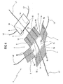
- variable size binder according to the present invention. It is noted that the wording "variable size" takes into account that such binder is suitable for enclosing an amount of documents so that the overall size of the binder is substantially equal to the size of the documents contained therein, and in particular is reduced in the case of few documents contained.
- Binder 1 is partly obtained by bending a rough shape 2 having a central rectangular or square panel and four wings that extend from the four side edges of the central panel.
- Said central panel defines a bottom wall 3 of binder 1, suitable for contacting a face of the documents included in binder 1, whereas said wings respectively define a first, a second, a third and a fourth side wall of binder 1, respectively indicated with reference numerals 4, 5, 6, 7.
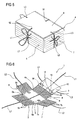
- Said side 4, 5, 6, 7 and bottom 3 walls therefore define an outer enclosure for containing the material to be filed and suitable for taking an open configuration ( figures 1 , 2A, 2B ), wherein it can receive the material to be filed or allow taking the material filed therein, and a closed configuration ( figure 5 ) wherein it can be arranged on a shelf or other place suitable for the storage thereof.
- the first side wall 4 exhibits an edge 4a connected to the bottom wall 3 and defining a folding line of the first side wall 4 relative to the bottom wall 3.
- the other walls 5, 6, 7 exhibit respective edges 5a, 6a, 7a defining as many folding lines of said side walls 5, 6, 7 relative to the bottom wall 3.
- Each side wall 4, 5, 6, 7 is therefore suitable for folding on the bottom wall 3 around the respective edge 4a, 5a, 6a, 7a that connects it to the bottom wall 3 so that a space “S” is defined between the side walls 4, 5, 6, 7 and the bottom wall 3 wherein the material "M” to be filed is received.
- material "M” to be filed may consist of a package of sheets, documents, catalogues or other paper or plastic material suitable for filing into folders.
- the side walls 4, 5, 6, 7 exhibit a plurality of pre-weakening lines 4b, 5b, 6b, 7b parallel to edges 4a, 5a, 6a, 7a.
- pre-weakening lines 4b, 5b, 6b, 7b allow a simple and practical folding of each side wall 4, 5, 6, 7 around material "M” present in said space "S” thus avoiding irritating bends that would oppose a proper closing of binder 1.
- the side walls 4, 5, 6, 7 may be folded easily for taking right angle edges so as to make binder 1 take a substantially box shaped outer shape.
- the first wall 4 and the second wall 5 are arranged in a position opposite each other, that is, they are connected to respective opposite sides of said central rectangular panel.
- the first and the second wall 4, 5 cooperate with each other for defining a side and top closure of binder 1.
- the third wall 6 and the fourth wall 7 are also arranged in a position opposite each other relative to the central panel.
- the third and the fourth wall 6, 7 cooperate with each other for defining a side closure of binder 1.
- said space "S" is substantially closed and delimited both laterally and at the top, whereas at the bottom it is delimited by the bottom wall 3.
- the first side wall 4 is extensible along a direction of approach and removal relative to the corresponding edge 4a. More in detail, the first side wall 4 is extensible for varying its surface extension so as to align with the bottom wall irrespective of the amount of material to be filed included within said space "S". By the term alignment it is meant the overlapping between the outer perimeter of the first side wall 4 and the outer perimeter of the bottom wall 3.
- the first side wall 4 comprises a first portion 8, directly connected to the bottom wall by said edge 4a and provided with the pre-weakening lines 4b, and a second portion 9 substantially shaped as an envelope and fitted on the first portion 8 at an end of the latter opposite said edge 4a.
- the second portion 9 is fitted on the first portion 8, that is, the first portion 8 is inserted in a front opening "A" of the second portion 9, so that the second portion 9 is movable in approach and in removal relative to the respective edge 4a.
- said first and second portion 8, 9 have a surface extension substantially equal to the surface extension of the bottom wall 3.
- the first side wall 4 is extensible between a minimum extension configuration ( figures 2B and 3A ), wherein the first portion 8 is entirely inserted into the second portion 9 for defining an overall extension substantially equal to the bottom wall 3, and a maximum extension configuration ( figures 2A and 3B ), wherein the first portion 8 is almost entirely extracted from the second portion 9 for defining an overall extension substantially equal to twice the bottom wall 3.
- the second portion 9 may therefore always be above the bottom wall 3 and aligned with the latter, since it is possible to act by increasing or decreasing the insertion of the first portion 8 into the second portion 9 based on a larger or smaller thickness of material "M" included within space "S".
- fixing means 10 active between the first and the second portion 8, 9 for steadily locking the second portion 9 relative to the first portion 8 at a plurality of predetermined configurations.
- the fixing means 10 are of the releasable type for allowing the modification of the positioning of the second portion 9 relative to the first portion 8, in particular when it is necessary to vary the amount of material "M" filed within space "S".
- Figure 1 shows a first embodiment of binder 1, wherein the fixing means 10 comprise a pair of buttons 11 fixed to the second portion 9, and a plurality of second buttons 12 fixed to the first portion 8 and which can be connected snap-wise with the first buttons 11. Said second buttons 12 are arranged in an aligned configuration along the sliding direction of the second portion 9 on the first portion 8, preferably on two parallel rows.
- buttons 11 and 12 are arranged according to a respective row in a median portion of the second portion 9 and of the first portion 8 of wall 4.
- Figure 4 shows a second embodiment of binder 1, wherein the fixing means 10 comprise a connection with Velcro ® having a pair of strips 13 fixed on the first portion 8 in alignment along the sliding direction of the second portion 9 on the first portion 8, and a pair of gripping elements 14 fixed to the second portion 9 and steadily engageable each with a corresponding strip 13.
- the fixing means 10 comprise a connection with Velcro ® having a pair of strips 13 fixed on the first portion 8 in alignment along the sliding direction of the second portion 9 on the first portion 8, and a pair of gripping elements 14 fixed to the second portion 9 and steadily engageable each with a corresponding strip 13.
- the fixing means 10 are defined by a pair of tabs 15 hinged to portion 9 of wall 4.
- Tabs 15 are each provided with an adhesive element 16 arranged on the inner surface thereof or facing portion 8 of wall 4 for attaching thereon.
- button 11 and/or gripping elements 14 and/or tabs 15 are arranged in the proximity of an end of the second portion 9 facing the respective edge 4a, that is, at said front opening "A".
- Binder 1 comprises one or more strings that can be tied to each other having the function of steadily coupling two parts of binder 1 to each other. As an alternative, the same parts are steadily coupled to each other by snap-wise connections, according to alternative embodiments not shown.
- a first string "L1" is provided to cross the bottom wall 3 through a first and a second hole 31 and 32.
- string L1 is fixed to portion 9 within the same.
- string L1 has a development at least coinciding with a corresponding outer peripheral development of binder 1 in a maximum extension configuration, as schematically shown in figure 5 .
- the fixing means 10 comprise a pair of strings "L1" of which a first one associated to the bottom wall 3 and which extends towards wall 5 and a second one associated to an end of the second portion 9 opposite relative to the front opening "A", that is, the free end of the second portion 9; in this way, strings L1 may be tied to one another with binder 1 closed.
- a pair of strings "L2" is preferably provided at the third and fourth side wall 6, 7. Strings L2 are fixed to the bottom wall 3 and extend towards the side walls 6, 7.
- a first and a second string "L3" extend from the side wall 4, in particular from the second portion 9 of the side wall 4, crosswise relative to the direction of insertion of portion 9 on portion 8.
- Each string L2 is positioned relative to a corresponding string L3 so as to tie therewith in the closed configuration of binder 1 shown in figure 5 , so as to keep the bottom wall 3 and the second portion 9 of the first wall 4 close.
- said bottom wall 3 is defined by a pair of sheets overlapped to each other for withstanding the strains due to said strings L1, L2 and L3.
- binder 1 is made of cardboard.
- the present invention attains the proposed objects, overcoming the disadvantages mentioned in the prior art.
- a side wall having a first and a second portion contiguous to each other and connected in a telescopic manner for overlapping according to a plurality of different operating configurations allows varying the geometry of the binder and allowing the adaptation of the same to different sizes of the material filed therein.
- Each of the above different operating configurations in fact allows a different overall surface extension of the first side wall, which can therefore be adapted for allowing a same alignment between the first side wall and the bottom wall irrespective of the amount of material to be filed included in the binder.
- the fixing means and the strings further allow keeping the configuration thus obtained steadily, which allows the binder to be handled safely.
- the binder according to the invention may contain documents without needing any permanent modifications and/or interventions to the documents themselves, such as for example punching needed for filing into ring binders of the prior art.
Landscapes
- Sheet Holders (AREA)
- Diaphragms For Electromechanical Transducers (AREA)
Claims (12)
- Ordner, umfassend eine äußere Umhüllung, die zum Einnehmen einer offenen Konfiguration und einer geschlossenen Konfiguration geeignet ist und innen einen Raum (S) zur Aufnahme von abzulegendem Material (M) definiert, wobei die Umhüllung eine untere Wand (3) und mindestens eine erste Wand (4) mit einem Rand (4a) aufweist, der mit der unteren Wand (3) verbunden und in der geschlossenen Konfiguration der Umhüllung zur Anordnung über der unteren Wand (3) geeignet ist; wobei die erste Wand (4) zum Variieren ihrer Oberflächenausdehnung ausdehnbar ist, sodass unabhängig von der Menge abzulegenden Materials, das in diesem Raum (S) beinhaltet ist, dieselbe Ausrichtung zwischen der ersten Wand (4) und der unteren Wand (3) gestattet wird, wobei die erste Wand (4) einen ersten Abschnitt (8) und einen zweiten Abschnitt (9) umfasst, die miteinander teleskopartig verbunden sind, wobei der erste Abschnitt (8) und der zweite Abschnitt (9) aneinander angrenzen und zumindest teilweise gemäß einer Vielzahl von unterschiedlichen Betriebskonfigurationen einander überlappt werden können, wobei jede Betriebskonfiguration eine entsprechende Oberflächenausdehnung der ersten Wand (4) definiert, wobei der erste Abschnitt (8) den Rand (4a) aufweist, der mit der unteren Wand (3) verbunden ist, wobei der zweite Abschnitt (9) eine Hüllenform zum verschiebbaren Aufsetzen auf den ersten Abschnitt (8) an einem Ende des ersten Abschnitts (8) gegenüber dem Rand (4a) aufweist, wobei der Ordner dadurch gekennzeichnet ist, dass er Fixiermittel (10) umfasst, die zwischen dem ersten und dem zweiten Abschnitt (8, 9) zum andauernden Fixieren des zweiten Abschnitts (9) relativ zum ersten Abschnitt (8) bei einer Vielzahl von festgelegten Konfigurationen aktiv sind, wobei die Fixiermittel (10) lösbar sind, um eine Änderung der Positionierung des zweiten Abschnitts (9) relativ zum ersten Abschnitt (8) zu gestatten.
- Ordner nach Anspruch 1, dadurch gekennzeichnet, dass der zweite Abschnitt (9) eine Oberflächenausdehnung aufweist, die im Wesentlichen der Oberflächenausdehnung des ersten Abschnitts (8) entspricht.
- Ordner nach Anspruch 1, dadurch gekennzeichnet, dass der zweite Abschnitt (9) eine Oberflächenausdehnung aufweist, die im Wesentlichen der Oberflächenausdehnung des unteren Abschnitts (3) entspricht.
- Ordner nach einem oder mehreren der Ansprüche 1 bis 3, dadurch gekennzeichnet, dass die erste Wand (4) zum Einnehmen einer minimalen Ausdehnungskonfiguration ausdehnbar ist, wobei der erste Abschnitt (8) vollständig in den zweiten Abschnitt (9) zum Definieren einer Gesamtausdehnung eingefügt ist, die im Wesentlichen der unteren Wand (3) entspricht, und einer maximalen Ausdehnungskonfiguration, wobei der erste Abschnitt (8) zumindest teilweise aus dem zweiten Abschnitt (9) zum Definieren einer Gesamtausdehnung herausgezogen ist, die größer als die untere Wand (3) ist.
- Ordner nach Anspruch 1, dadurch gekennzeichnet, dass die Fixiermittel (10) mindestens ein erstes Element (11) umfassen, das am zweiten Abschnitt (9) fixiert ist, sowie eine Vielzahl von zweiten Elementen (12), die am ersten Abschnitt (8) fixiert sind, und die einschnappend mit dem ersten Element (11) verbunden werden können, wobei die zweiten Elemente (12) entlang einer Richtung des Verschiebens des zweiten Abschnitts (9) auf dem ersten Abschnitt (8) ausgerichtet angeordnet sind.
- Ordner nach Anspruch 1, dadurch gekennzeichnet, dass die Fixiermittel (10) eine Verbindung mit Velcro® umfassen, wobei die Verbindung mindestens einen Streifen (13) umfasst, der am ersten Abschnitt (8) fixiert ist und entlang einer Richtung des Verschiebens des zweiten Abschnitts (9) auf dem ersten Abschnitt (8) ausgerichtet ist, sowie mindestens ein Greifelement (14), das am zweiten Abschnitt (9) fixiert ist und andauernd mit dem Streifen (13) in Eingriff gebracht werden kann.
- Ordner nach Anspruch 1, dadurch gekennzeichnet, dass er mindestens einen lösbaren Verschluss umfasst, der zwischen dem zweiten Abschnitt (9) der ersten Wand (4) und der unteren Wand (3) zum Erhalt eines andauernden und umkehrbaren Verschlusses des Ordners (1) aktiv ist.
- Ordner nach einem oder mehreren der vorangehenden Ansprüche, dadurch gekennzeichnet, dass die erste Wand (4) entsprechende Vorschwächungslinien (4b) aufweist, die parallel zum Rand (4a) sind und entsprechende Faltlinien zum Anpassen der ersten Wand (4) an die äußere Form des abzulegenden Materials (M) definieren, das in dem Raum (S) enthalten ist.
- Ordner nach einem oder mehreren der vorangehenden Ansprüche, dadurch gekennzeichnet, dass er eine zweite Wand (5) umfasst, die relativ zum Rand (4a) der ersten Wand (4) gegenüberliegend mit der unteren Wand (3) verbunden ist und mit der ersten Wand (4) zusammenwirkt, um einen seitlichen Verschluss des Ordners (1) zu erhalten.
- Ordner nach Anspruch 9, dadurch gekennzeichnet, dass er eine dritte und eine vierte Wand (6, 7) umfasst, die mit der unteren Wand (3) verbunden und relativ zueinander in gegenüberliegender Position angeordnet sind, wobei die dritte und vierte Wand (6, 7) quer zur ersten und zweiten Wand (4, 5) angeordnet sind, um einen seitlichen Verschluss des Ordners (1) zu vervollständigen.
- Ordner nach Anspruch 9 oder 10, dadurch gekennzeichnet, dass die zweite Wand (5) und/oder die dritte und vierte Wand (6, 7) entsprechende Vorschwächungslinien (5b, 6b, 7b) aufweisen, die entsprechende Faltlinien zum Anpassen an die äußere Abmessung des abzulegenden Materials (M) definieren, das in dem Raum (S) enthalten ist.
- Ordner nach einem oder mehreren der vorangehenden Ansprüche, dadurch gekennzeichnet, dass er aus Karton gefertigt ist.
Applications Claiming Priority (1)
| Application Number | Priority Date | Filing Date | Title |
|---|---|---|---|
| ITBO20080350 ITBO20080350A1 (it) | 2008-06-04 | 2008-06-04 | Raccoglitore ad ingombro variabile. |
Publications (2)
| Publication Number | Publication Date |
|---|---|
| EP2130683A1 EP2130683A1 (de) | 2009-12-09 |
| EP2130683B1 true EP2130683B1 (de) | 2012-12-05 |
Family
ID=40301539
Family Applications (1)
| Application Number | Title | Priority Date | Filing Date |
|---|---|---|---|
| EP20090161554 Not-in-force EP2130683B1 (de) | 2008-06-04 | 2009-05-29 | Verbinder mit variabler Größe |
Country Status (4)
| Country | Link |
|---|---|
| EP (1) | EP2130683B1 (de) |
| ES (1) | ES2404056T3 (de) |
| IT (1) | ITBO20080350A1 (de) |
| RU (1) | RU2507077C2 (de) |
Cited By (1)
| Publication number | Priority date | Publication date | Assignee | Title |
|---|---|---|---|---|
| US11053049B1 (en) | 2018-08-02 | 2021-07-06 | Idongesit Elijah Inyang | Size adjustable box |
Families Citing this family (4)
| Publication number | Priority date | Publication date | Assignee | Title |
|---|---|---|---|---|
| GB2483656A (en) * | 2010-09-14 | 2012-03-21 | Anthony F England | Expandable Pocket |
| DE102011053061A1 (de) * | 2011-07-16 | 2013-01-17 | Egon Heimann | Anpassbare Umschlagmappe |
| FR3022184B1 (fr) * | 2014-06-11 | 2018-03-02 | Novaclass | Chemise de rangement/classement |
| RU199873U1 (ru) * | 2020-03-10 | 2020-09-24 | Общество с ограниченной ответственностью "Ваш Архив" (ООО "Ваш Архив") | Архивная папка |
Family Cites Families (5)
| Publication number | Priority date | Publication date | Assignee | Title |
|---|---|---|---|---|
| FR2082000A5 (de) | 1969-12-05 | 1971-12-10 | Emballage Carton | |
| FR2524391A1 (fr) * | 1982-04-05 | 1983-10-07 | Nicollet & Cie Ets | Chemise de classement extensible |
| DE19620506B4 (de) * | 1996-05-22 | 2007-05-03 | Mappei-Organisationsmittel Gmbh | Schriftgut-Sammelmappe |
| DE19735383A1 (de) * | 1997-08-14 | 1999-02-18 | Juergen Tepe | Umschlag |
| GB0319439D0 (en) * | 2003-08-19 | 2003-09-17 | Tillbrook Chris J | Variable capacity folder |
-
2008
- 2008-06-04 IT ITBO20080350 patent/ITBO20080350A1/it unknown
-
2009
- 2009-05-29 ES ES09161554T patent/ES2404056T3/es active Active
- 2009-05-29 EP EP20090161554 patent/EP2130683B1/de not_active Not-in-force
- 2009-06-03 RU RU2009120973/12A patent/RU2507077C2/ru not_active IP Right Cessation
Cited By (1)
| Publication number | Priority date | Publication date | Assignee | Title |
|---|---|---|---|---|
| US11053049B1 (en) | 2018-08-02 | 2021-07-06 | Idongesit Elijah Inyang | Size adjustable box |
Also Published As
| Publication number | Publication date |
|---|---|
| RU2009120973A (ru) | 2010-12-10 |
| EP2130683A1 (de) | 2009-12-09 |
| RU2507077C2 (ru) | 2014-02-20 |
| ES2404056T3 (es) | 2013-05-23 |
| ITBO20080350A1 (it) | 2009-12-05 |
Similar Documents
| Publication | Publication Date | Title |
|---|---|---|
| US6431779B1 (en) | Binder with expandable pocket | |
| US6209778B1 (en) | Slash jacket with a retractable attachment member | |
| EP2130683B1 (de) | Verbinder mit variabler Größe | |
| US6648374B2 (en) | Presentation devices with indexed holders | |
| US20060055167A1 (en) | Sheet retaining devices such as binders having pockets with corner locks | |
| US20150014978A1 (en) | Cover, Coupling Element and Folder | |
| US20030234281A1 (en) | Expandable file folder | |
| RU2359838C2 (ru) | Папка для документов, имеющая по меньшей мере два клапана | |
| US10118432B2 (en) | Notebook squaring apparatus | |
| US20110163153A1 (en) | document file | |
| JPS6021253Y2 (ja) | ノ−トブツク | |
| US20070183840A1 (en) | Organizer | |
| WO2008085121A1 (en) | Filing box | |
| KR102694778B1 (ko) | 앨범 케이스 | |
| US7913875B2 (en) | Dispenser for folders | |
| KR20070001282U (ko) | 커버지 | |
| RU131670U1 (ru) | Короб архивный со складывающимися упорами | |
| WO2008142573A2 (en) | Multi-function element from a system for the filling or the storage of an article | |
| JP3162719U (ja) | ファイル | |
| GB2366759A (en) | Binder with slots in cover for binding elements | |
| AU2005100438A4 (en) | Locking Mechanism for a Folder/Binder | |
| RU74341U1 (ru) | Архивная папка-короб | |
| JP2013086344A5 (de) | ||
| CN101780739A (zh) | 文件装订用的封面 | |
| JP2011093534A (ja) | 組み立て箱 |
Legal Events
| Date | Code | Title | Description |
|---|---|---|---|
| PUAI | Public reference made under article 153(3) epc to a published international application that has entered the european phase |
Free format text: ORIGINAL CODE: 0009012 |
|
| AK | Designated contracting states |
Kind code of ref document: A1 Designated state(s): AT BE BG CH CY CZ DE DK EE ES FI FR GB GR HR HU IE IS IT LI LT LU LV MC MK MT NL NO PL PT RO SE SI SK TR |
|
| 17P | Request for examination filed |
Effective date: 20100503 |
|
| GRAP | Despatch of communication of intention to grant a patent |
Free format text: ORIGINAL CODE: EPIDOSNIGR1 |
|
| GRAS | Grant fee paid |
Free format text: ORIGINAL CODE: EPIDOSNIGR3 |
|
| GRAA | (expected) grant |
Free format text: ORIGINAL CODE: 0009210 |
|
| AK | Designated contracting states |
Kind code of ref document: B1 Designated state(s): AT BE BG CH CY CZ DE DK EE ES FI FR GB GR HR HU IE IS IT LI LT LU LV MC MK MT NL NO PL PT RO SE SI SK TR |
|
| REG | Reference to a national code |
Ref country code: GB Ref legal event code: FG4D |
|
| REG | Reference to a national code |
Ref country code: CH Ref legal event code: EP |
|
| REG | Reference to a national code |
Ref country code: AT Ref legal event code: REF Ref document number: 587056 Country of ref document: AT Kind code of ref document: T Effective date: 20121215 |
|
| REG | Reference to a national code |
Ref country code: IE Ref legal event code: FG4D |
|
| REG | Reference to a national code |
Ref country code: DE Ref legal event code: R096 Ref document number: 602009011665 Country of ref document: DE Effective date: 20130131 |
|
| REG | Reference to a national code |
Ref country code: AT Ref legal event code: MK05 Ref document number: 587056 Country of ref document: AT Kind code of ref document: T Effective date: 20121205 |
|
| REG | Reference to a national code |
Ref country code: NL Ref legal event code: T3 |
|
| PG25 | Lapsed in a contracting state [announced via postgrant information from national office to epo] |
Ref country code: FI Free format text: LAPSE BECAUSE OF FAILURE TO SUBMIT A TRANSLATION OF THE DESCRIPTION OR TO PAY THE FEE WITHIN THE PRESCRIBED TIME-LIMIT Effective date: 20121205 Ref country code: HR Free format text: LAPSE BECAUSE OF FAILURE TO SUBMIT A TRANSLATION OF THE DESCRIPTION OR TO PAY THE FEE WITHIN THE PRESCRIBED TIME-LIMIT Effective date: 20121205 Ref country code: SE Free format text: LAPSE BECAUSE OF FAILURE TO SUBMIT A TRANSLATION OF THE DESCRIPTION OR TO PAY THE FEE WITHIN THE PRESCRIBED TIME-LIMIT Effective date: 20121205 Ref country code: NO Free format text: LAPSE BECAUSE OF FAILURE TO SUBMIT A TRANSLATION OF THE DESCRIPTION OR TO PAY THE FEE WITHIN THE PRESCRIBED TIME-LIMIT Effective date: 20130305 Ref country code: LT Free format text: LAPSE BECAUSE OF FAILURE TO SUBMIT A TRANSLATION OF THE DESCRIPTION OR TO PAY THE FEE WITHIN THE PRESCRIBED TIME-LIMIT Effective date: 20121205 |
|
| REG | Reference to a national code |
Ref country code: CH Ref legal event code: NV Representative=s name: WAGNER PATENT AG, CH |
|
| REG | Reference to a national code |
Ref country code: ES Ref legal event code: FG2A Ref document number: 2404056 Country of ref document: ES Kind code of ref document: T3 Effective date: 20130523 |
|
| REG | Reference to a national code |
Ref country code: LT Ref legal event code: MG4D |
|
| PG25 | Lapsed in a contracting state [announced via postgrant information from national office to epo] |
Ref country code: CY Free format text: LAPSE BECAUSE OF FAILURE TO SUBMIT A TRANSLATION OF THE DESCRIPTION OR TO PAY THE FEE WITHIN THE PRESCRIBED TIME-LIMIT Effective date: 20121205 Ref country code: PL Free format text: LAPSE BECAUSE OF FAILURE TO SUBMIT A TRANSLATION OF THE DESCRIPTION OR TO PAY THE FEE WITHIN THE PRESCRIBED TIME-LIMIT Effective date: 20121205 Ref country code: SI Free format text: LAPSE BECAUSE OF FAILURE TO SUBMIT A TRANSLATION OF THE DESCRIPTION OR TO PAY THE FEE WITHIN THE PRESCRIBED TIME-LIMIT Effective date: 20121205 Ref country code: GR Free format text: LAPSE BECAUSE OF FAILURE TO SUBMIT A TRANSLATION OF THE DESCRIPTION OR TO PAY THE FEE WITHIN THE PRESCRIBED TIME-LIMIT Effective date: 20130306 Ref country code: LV Free format text: LAPSE BECAUSE OF FAILURE TO SUBMIT A TRANSLATION OF THE DESCRIPTION OR TO PAY THE FEE WITHIN THE PRESCRIBED TIME-LIMIT Effective date: 20121205 |
|
| PG25 | Lapsed in a contracting state [announced via postgrant information from national office to epo] |
Ref country code: AT Free format text: LAPSE BECAUSE OF FAILURE TO SUBMIT A TRANSLATION OF THE DESCRIPTION OR TO PAY THE FEE WITHIN THE PRESCRIBED TIME-LIMIT Effective date: 20121205 |
|
| PG25 | Lapsed in a contracting state [announced via postgrant information from national office to epo] |
Ref country code: EE Free format text: LAPSE BECAUSE OF FAILURE TO SUBMIT A TRANSLATION OF THE DESCRIPTION OR TO PAY THE FEE WITHIN THE PRESCRIBED TIME-LIMIT Effective date: 20121205 Ref country code: IS Free format text: LAPSE BECAUSE OF FAILURE TO SUBMIT A TRANSLATION OF THE DESCRIPTION OR TO PAY THE FEE WITHIN THE PRESCRIBED TIME-LIMIT Effective date: 20130405 Ref country code: BG Free format text: LAPSE BECAUSE OF FAILURE TO SUBMIT A TRANSLATION OF THE DESCRIPTION OR TO PAY THE FEE WITHIN THE PRESCRIBED TIME-LIMIT Effective date: 20130305 Ref country code: SK Free format text: LAPSE BECAUSE OF FAILURE TO SUBMIT A TRANSLATION OF THE DESCRIPTION OR TO PAY THE FEE WITHIN THE PRESCRIBED TIME-LIMIT Effective date: 20121205 |
|
| PGFP | Annual fee paid to national office [announced via postgrant information from national office to epo] |
Ref country code: IE Payment date: 20130524 Year of fee payment: 5 Ref country code: GB Payment date: 20130531 Year of fee payment: 5 Ref country code: CZ Payment date: 20130523 Year of fee payment: 5 Ref country code: CH Payment date: 20130524 Year of fee payment: 5 |
|
| PG25 | Lapsed in a contracting state [announced via postgrant information from national office to epo] |
Ref country code: RO Free format text: LAPSE BECAUSE OF FAILURE TO SUBMIT A TRANSLATION OF THE DESCRIPTION OR TO PAY THE FEE WITHIN THE PRESCRIBED TIME-LIMIT Effective date: 20121205 Ref country code: PT Free format text: LAPSE BECAUSE OF FAILURE TO SUBMIT A TRANSLATION OF THE DESCRIPTION OR TO PAY THE FEE WITHIN THE PRESCRIBED TIME-LIMIT Effective date: 20130405 |
|
| PGFP | Annual fee paid to national office [announced via postgrant information from national office to epo] |
Ref country code: IT Payment date: 20130524 Year of fee payment: 5 Ref country code: FR Payment date: 20130621 Year of fee payment: 5 Ref country code: NL Payment date: 20130524 Year of fee payment: 5 |
|
| PGFP | Annual fee paid to national office [announced via postgrant information from national office to epo] |
Ref country code: BE Payment date: 20130626 Year of fee payment: 5 |
|
| PLBE | No opposition filed within time limit |
Free format text: ORIGINAL CODE: 0009261 |
|
| STAA | Information on the status of an ep patent application or granted ep patent |
Free format text: STATUS: NO OPPOSITION FILED WITHIN TIME LIMIT |
|
| PG25 | Lapsed in a contracting state [announced via postgrant information from national office to epo] |
Ref country code: DK Free format text: LAPSE BECAUSE OF FAILURE TO SUBMIT A TRANSLATION OF THE DESCRIPTION OR TO PAY THE FEE WITHIN THE PRESCRIBED TIME-LIMIT Effective date: 20121205 |
|
| PGFP | Annual fee paid to national office [announced via postgrant information from national office to epo] |
Ref country code: DE Payment date: 20130731 Year of fee payment: 5 |
|
| 26N | No opposition filed |
Effective date: 20130906 |
|
| PG25 | Lapsed in a contracting state [announced via postgrant information from national office to epo] |
Ref country code: MC Free format text: LAPSE BECAUSE OF FAILURE TO SUBMIT A TRANSLATION OF THE DESCRIPTION OR TO PAY THE FEE WITHIN THE PRESCRIBED TIME-LIMIT Effective date: 20121205 |
|
| REG | Reference to a national code |
Ref country code: DE Ref legal event code: R097 Ref document number: 602009011665 Country of ref document: DE Effective date: 20130906 |
|
| REG | Reference to a national code |
Ref country code: CH Ref legal event code: PCAR Free format text: NEW ADDRESS: BAECHERSTRASSE 9, 8832 WOLLERAU (CH) |
|
| REG | Reference to a national code |
Ref country code: DE Ref legal event code: R119 Ref document number: 602009011665 Country of ref document: DE |
|
| REG | Reference to a national code |
Ref country code: NL Ref legal event code: V1 Effective date: 20141201 |
|
| REG | Reference to a national code |
Ref country code: CH Ref legal event code: PL |
|
| GBPC | Gb: european patent ceased through non-payment of renewal fee |
Effective date: 20140529 |
|
| PG25 | Lapsed in a contracting state [announced via postgrant information from national office to epo] |
Ref country code: CH Free format text: LAPSE BECAUSE OF NON-PAYMENT OF DUE FEES Effective date: 20140531 Ref country code: LI Free format text: LAPSE BECAUSE OF NON-PAYMENT OF DUE FEES Effective date: 20140531 Ref country code: CZ Free format text: LAPSE BECAUSE OF NON-PAYMENT OF DUE FEES Effective date: 20140529 |
|
| REG | Reference to a national code |
Ref country code: IE Ref legal event code: MM4A |
|
| REG | Reference to a national code |
Ref country code: DE Ref legal event code: R119 Ref document number: 602009011665 Country of ref document: DE Effective date: 20141202 |
|
| PG25 | Lapsed in a contracting state [announced via postgrant information from national office to epo] |
Ref country code: MT Free format text: LAPSE BECAUSE OF FAILURE TO SUBMIT A TRANSLATION OF THE DESCRIPTION OR TO PAY THE FEE WITHIN THE PRESCRIBED TIME-LIMIT Effective date: 20121205 Ref country code: NL Free format text: LAPSE BECAUSE OF NON-PAYMENT OF DUE FEES Effective date: 20141201 |
|
| REG | Reference to a national code |
Ref country code: FR Ref legal event code: ST Effective date: 20150130 |
|
| PG25 | Lapsed in a contracting state [announced via postgrant information from national office to epo] |
Ref country code: DE Free format text: LAPSE BECAUSE OF NON-PAYMENT OF DUE FEES Effective date: 20141202 Ref country code: IE Free format text: LAPSE BECAUSE OF NON-PAYMENT OF DUE FEES Effective date: 20140529 Ref country code: IT Free format text: LAPSE BECAUSE OF NON-PAYMENT OF DUE FEES Effective date: 20140529 |
|
| PG25 | Lapsed in a contracting state [announced via postgrant information from national office to epo] |
Ref country code: GB Free format text: LAPSE BECAUSE OF NON-PAYMENT OF DUE FEES Effective date: 20140529 Ref country code: FR Free format text: LAPSE BECAUSE OF NON-PAYMENT OF DUE FEES Effective date: 20140602 |
|
| PG25 | Lapsed in a contracting state [announced via postgrant information from national office to epo] |
Ref country code: TR Free format text: LAPSE BECAUSE OF FAILURE TO SUBMIT A TRANSLATION OF THE DESCRIPTION OR TO PAY THE FEE WITHIN THE PRESCRIBED TIME-LIMIT Effective date: 20121205 |
|
| PG25 | Lapsed in a contracting state [announced via postgrant information from national office to epo] |
Ref country code: MK Free format text: LAPSE BECAUSE OF FAILURE TO SUBMIT A TRANSLATION OF THE DESCRIPTION OR TO PAY THE FEE WITHIN THE PRESCRIBED TIME-LIMIT Effective date: 20121205 Ref country code: LU Free format text: LAPSE BECAUSE OF NON-PAYMENT OF DUE FEES Effective date: 20130529 Ref country code: HU Free format text: LAPSE BECAUSE OF FAILURE TO SUBMIT A TRANSLATION OF THE DESCRIPTION OR TO PAY THE FEE WITHIN THE PRESCRIBED TIME-LIMIT; INVALID AB INITIO Effective date: 20090529 |
|
| REG | Reference to a national code |
Ref country code: ES Ref legal event code: FD2A Effective date: 20151229 |
|
| PG25 | Lapsed in a contracting state [announced via postgrant information from national office to epo] |
Ref country code: ES Free format text: LAPSE BECAUSE OF NON-PAYMENT OF DUE FEES Effective date: 20140530 |
|
| PG25 | Lapsed in a contracting state [announced via postgrant information from national office to epo] |
Ref country code: BE Free format text: LAPSE BECAUSE OF NON-PAYMENT OF DUE FEES Effective date: 20140531 |