EP2130730A2 - Agencement d'arbre d'essuie-glace et installation d'essuie-glace - Google Patents
Agencement d'arbre d'essuie-glace et installation d'essuie-glace Download PDFInfo
- Publication number
- EP2130730A2 EP2130730A2 EP20090100309 EP09100309A EP2130730A2 EP 2130730 A2 EP2130730 A2 EP 2130730A2 EP 20090100309 EP20090100309 EP 20090100309 EP 09100309 A EP09100309 A EP 09100309A EP 2130730 A2 EP2130730 A2 EP 2130730A2
- Authority
- EP
- European Patent Office
- Prior art keywords
- wiper shaft
- protective
- bearing unit
- wiper
- shaft arrangement
- Prior art date
- Legal status (The legal status is an assumption and is not a legal conclusion. Google has not performed a legal analysis and makes no representation as to the accuracy of the status listed.)
- Withdrawn
Links
- 230000001681 protective effect Effects 0.000 claims description 87
- XLYOFNOQVPJJNP-UHFFFAOYSA-N water Substances O XLYOFNOQVPJJNP-UHFFFAOYSA-N 0.000 claims description 23
- 230000002093 peripheral effect Effects 0.000 abstract description 18
- 230000000717 retained effect Effects 0.000 abstract 1
- 238000011161 development Methods 0.000 description 3
- 230000018109 developmental process Effects 0.000 description 3
- 238000006073 displacement reaction Methods 0.000 description 3
- 239000002184 metal Substances 0.000 description 2
- 230000000712 assembly Effects 0.000 description 1
- 238000000429 assembly Methods 0.000 description 1
- 230000005494 condensation Effects 0.000 description 1
- 238000009833 condensation Methods 0.000 description 1
- 238000002347 injection Methods 0.000 description 1
- 239000007924 injection Substances 0.000 description 1
- 230000014759 maintenance of location Effects 0.000 description 1
- 239000000243 solution Substances 0.000 description 1
- 239000007921 spray Substances 0.000 description 1
Images

Classifications
-
- B—PERFORMING OPERATIONS; TRANSPORTING
- B60—VEHICLES IN GENERAL
- B60S—SERVICING, CLEANING, REPAIRING, SUPPORTING, LIFTING, OR MANOEUVRING OF VEHICLES, NOT OTHERWISE PROVIDED FOR
- B60S1/00—Cleaning of vehicles
- B60S1/02—Cleaning windscreens, windows or optical devices
- B60S1/04—Wipers or the like, e.g. scrapers
- B60S1/32—Wipers or the like, e.g. scrapers characterised by constructional features of wiper blade arms or blades
- B60S1/34—Wiper arms; Mountings therefor
- B60S1/3488—Means for mounting wiper arms onto the vehicle
- B60S1/3493—Means for mounting the wiper shaft in the wiper bearing
-
- B—PERFORMING OPERATIONS; TRANSPORTING
- B60—VEHICLES IN GENERAL
- B60S—SERVICING, CLEANING, REPAIRING, SUPPORTING, LIFTING, OR MANOEUVRING OF VEHICLES, NOT OTHERWISE PROVIDED FOR
- B60S1/00—Cleaning of vehicles
- B60S1/02—Cleaning windscreens, windows or optical devices
- B60S1/04—Wipers or the like, e.g. scrapers
- B60S1/32—Wipers or the like, e.g. scrapers characterised by constructional features of wiper blade arms or blades
- B60S1/34—Wiper arms; Mountings therefor
- B60S1/3488—Means for mounting wiper arms onto the vehicle
- B60S1/3495—Means for mounting the drive mechanism to the wiper shaft
Definitions
- the invention relates to a wiper shaft arrangement for a windscreen wiper system according to the preamble of claim 1 and to a windshield wiper system, in particular for a motor vehicle according to claim 10.
- the invention has for its object to provide a wiper shaft assembly for a windshield wiper system, in which the storage unit is better protected against water and / or dirt. Furthermore, the object is to propose a windshield wiper system with a correspondingly optimized wiper shaft arrangement.
- the invention is based on the idea, in addition to or as an alternative to a protective cap provided in the upper region of the bearing unit, that the bearing unit, in particular laterally, extends beyond the free end of the wiper shaft in the axial direction.
- the protective apron is preferably a rotationally symmetrical component, in particular made of plastic, with a peripheral circumferential wall which extends in the axial direction beyond the lower end of the bearing unit.
- the protective skirt is preferred in which this is designed as a rotationally symmetrical component. It is particularly preferred if the protective apron, in order to ensure optimum protection against water and / or dirt, has a circumferentially closed peripheral wall, which is preferably guided radially outward at the lower end of the bearing unit. In this case, the circumferentially closed wall should be formed circumferentially closed at least in a region arranged directly radially outside the lower end of the bearing unit.
- the protective apron is fixed to the storage unit, there are different possibilities of realization.
- the bearing unit is held in addition to the positive locking frictionally on the bearing unit, in particular by an elastic expansion of the protective skirt during disassembly.
- the protective skirt exclusively frictionally, preferably the bearing unit radially clamping, secured against axial withdrawal, that is held on the bearing unit.
- the protective skirt is held in a circumferential groove of the bearing unit by a retaining section which radially delimits a passage opening for the bearing unit.
- This circumferential groove is preferably located on the end of a forming tube of the bearing unit, in which at least one bearing bush, preferably two bearing bushes spaced apart in the axial direction, is received for oscillating bearing of the wiper shaft.
- this circumferential groove is bounded in the axial direction down by a shoulder portion of a bearing bush, which projects beyond the lower end face of the forming tube (preferably metal tube) in the radial direction to the outside.
- a lower, preferably trough-like upwardly opening, protective cap is provided, which projects beyond the axially lower end of the protective skirt in the axial direction.
- the protective cap protrudes into an area which is enclosed radially on the outside of the protective apron. If a circumferential gap is provided radially between the protective cap and the protective apron, the protective cap and the protective apron act together in the manner of a labyrinth seal.
- the lower protective cap is held on a surface structure of the wiper shaft. It is particularly preferred if the protective cap is fixed in a form-fitting manner to the surface structure of the wiper shaft, in particular as a groove structure.
- the groove structure preferably comprises a multiplicity of circular grooves arranged next to one another in the axial direction, into which the protective cap can engage radially.
- the spring washer preferably has the function of an axial securing the bearing unit.
- the spring washer can be supported in the axial direction, for example on a lower thrust washer, or on a shoulder portion of a bearing bush or on the lower end face of a forming tube of the bearing unit.
- the protective cap in particular a form-fitting manner, is held on the protective apron.
- the protective cap preferably engages with a radially outer annular section in an inner peripheral groove of the protective apron.
- the provision of a separate protective cap is dispensed with and the protective apron is shaped in the manner of a one-piece combination of protective apron and protective cap.
- the protective skirt is formed such that it extends in a region below the lower end of the bearing unit radially inward, so as to provide optimum protection against ingress of water and / or dirt from below.
- the protective skirt in which it is designed such that it can serve in 180 ° rotated arrangement as an upper protective cap in an axial region between the free end of the wiper shaft and the upper end of the bearing unit on a surface structure of the wiper shaft is determinable.
- the storage unit can be optimally protected from all directions against ingress of water and / or against ingress of dirt.
- the invention leads to a windshield wiper system, in particular for a motor vehicle, with a previously described wiper shaft arrangement.
- the windshield wiper system is a front wiper system, in which case the wiper shaft is preferably driven in a pendulum fashion via a wiper linkage.
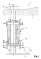
- Fig. 1 is a detail of a windshield wiper system 1 with a wiper shaft assembly 2 is shown.
- the wiper shaft arrangement 2 comprises a wiper shaft 3, which rotatably carries a wiper arm 5 in the region of its free upper end 4. With its lower end, the wiper shaft 3 is fixed to a crank plate 6 of an otherwise not shown, known per se crank linkage.
- a crank plate 6 On the crank plate 6 is a ball head 7 (pivot pin) for connecting the crank plate 6 to joint rods, not shown.
- the crank plate 6 and thus the wiper shaft 3 and the wiper arm 5 is oscillated about the longitudinal axis L of the wiper shaft.
- the wiper shaft 3 passes through in the axial direction a bearing unit 8.
- This comprises a rotatably arranged forming tube 9 (metal tube), in which two axially spaced bearing bushes 10, 11 are received, which store the wiper shaft 3 directly.
- On top of the bearing unit 8 is an upper thrust washer 12, on which in the axial direction from above a spring washer 13 (Speednut) is supported.
- the spring washer 13 is clawed by means of circumferentially spaced, radially inwardly projecting spring tabs 14 having a groove structure formed as an upper axial surface structure 15.
- the surface structure 15 continues, starting from the bearing unit 8, for a distance in the axial direction upwards.
- the upper surface structure 15 serves at the same time for positive retention of an upper protective cap 16 which, like the spring washer 13 and the upper thrust washer 12, is penetrated by the wiper shaft 3 in the axial direction.
- the downwardly open upper, trough-shaped, protective cap 16 extends in the axial direction over the upper, formed by the thrust washer 12 end of the bearing unit 8 out in the axial direction down to a region radially outside the peripheral surface of the forming tube 9.
- the upper cap 16 encloses So both the spring washer 13 and the upper thrust washer 12 and the upper end face of the forming tube 9 radially outward.
- a lower thrust washer 17 which is secured by means of another spring washer 18 (Speednut) against axial displacement (outward).
- the lower spring washer 18 is held by means of radially inwardly projecting spring tabs 19 on an axially lower, also groove-shaped surface structure 20 of the wiper shaft 3.
- Fig. 1 shows, the bearing unit 8 is secured against axial displacement upwards with the help of the upper spring washer and against axial displacement down relative to the wiper shaft 3 by means of the lower spring washer 18.
- a rotationally symmetrical protective apron 21 designed as a plastic part is provided.
- This has an upper, radially inwardly directed holding portion 22, with which the protective skirt 21 is held positively in a circumferential groove 23 of the bearing unit 8.
- the protective skirt 21 With a circumferentially closed peripheral wall 24, the protective skirt 21 extends in the axial direction downwards beyond the bearing unit 8.
- the peripheral wall 24 is contoured substantially circular cylindrical.
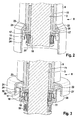
- Fig. 2 is a possible design and arrangement of trained as a plastic injection molded protective apron 21 shown.
- the annular, radially inwardly projecting holding portion 22 which defines radially inwardly a through hole 25 which is axially penetrated by the bearing unit 8.
- a gradation 26 is provided on the outer circumference.
- the step 26 forms together with an annular, radially outwardly projecting and the lower end face of the forming tube radially cross-shoulder portion 27 of the lower bearing bush 11 has a circumferential groove 24 into which the protective skirt 21 engages with its holding portion 22 radially.
- a peripherally closed circumferential wall 24 Adjoining the holding section 22 axially is a peripherally closed circumferential wall 24, which extends beyond the lower end of the bearing unit 8 formed by the lower stop disk 17 in the axial direction.
- Fig. 2 is clearly the lower spring washer 18 to recognize, which is clawed with its spring tabs 19 with the lower, groove-shaped surface structure 20 of the wiper shaft 3.
- the surface structure 20 consists of a plurality of axially adjacent, circumferential, annular grooves.
- Fig. 3 is shown in sections an alternative embodiment of a wiper shaft assembly 2, in which the protective skirt 21 held in a circumferential groove 23 of the bearing unit 8 cooperates with a lower protective cap 28 in the manner of a labyrinth seal.
- the axial extension of the peripheral closed peripheral wall 24 is substantially shorter than in the embodiment according to Fig. 2 .
- the peripheral wall 29 projects beyond the lower end of the peripheral wall 24 of the protective skirt 21 in the axial direction.
- the upper end of the peripheral wall 29 of the protective cap 28 is received in a region enclosed by the peripheral wall 24 region of the protective skirt 21, so that an immediate inflow of water from above is reliably avoided.
- a circumferential gap 30 is formed between the outer periphery of the peripheral wall 29 and the inner periphery of the peripheral wall 24 of the protective skirt 24, a circumferential gap 30 is formed.
- the lower cap 28 is fixed in an axially spaced from the lower protective skirt 21 area with an annular fixing portion 31 on the lower surface structure 20. Spaced axially apart from the fixing section 31, the lower spring washer 18 engages positively with its spring tabs 19 in the same surface structure 20. It can be seen that the lower protective cap 28 is supported in the axial direction upward on the lower spring washer 18.
- annular groove 32 is introduced in the annular groove 32 engages from radially inwardly a ring portion 33 of the lower cap 28 in the radial direction to the outside. In other words, the ring portion 33 is locked with the annular groove 32.
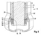
- the embodiment shown according to Fig. 4 is radially between the lower cap 28 and the lower protective skirt 21 no circumferential gap formed, whereby the protection against water and dirt is further optimized.
- annular, radially inwardly directed radial portion 34 which defines a central water outlet opening 35 in its radially inner region, through which in a region within the protective skirt 21 reached water, such as condensation down can flow out.
- the lower protective skirt 21 is not received in a circumferential groove of the bearing unit 8, but lies, the bearing unit 8 radially inwardly clamping, on the outer circumference of the forming tube 9 in a lower edge region.
- the forming tube 9 clamping holding portion 21 the circumferentially closed peripheral wall 24 extends in the axial direction downwards.
- the lower region of the protective skirt 21 is formed by a cap portion 36 which is at least approximately shaped like a lower protective cap.
- the cap portion 36 includes a radially inwardly extending radial portion 34 which defines a central water drain opening 35 in an axially lower region.
- Protective apron 21 shown can also be used as an upper protective cap, in which case the water outlet opening 35 is penetrated by the wiper shaft 3 in the axial direction and the peripheral edge 37 of the water outlet opening 35 for positive connection with an upper surface structure of the wiper shaft 3 is used.
Landscapes
- Engineering & Computer Science (AREA)
- Mechanical Engineering (AREA)
- Sliding-Contact Bearings (AREA)
- Sealing Of Bearings (AREA)
Applications Claiming Priority (1)
| Application Number | Priority Date | Filing Date | Title |
|---|---|---|---|
| DE102008002147.4A DE102008002147B4 (de) | 2008-06-02 | 2008-06-02 | Wischerwellenanordnung sowie Scheibenwischanlage |
Publications (1)
| Publication Number | Publication Date |
|---|---|
| EP2130730A2 true EP2130730A2 (fr) | 2009-12-09 |
Family
ID=40996695
Family Applications (1)
| Application Number | Title | Priority Date | Filing Date |
|---|---|---|---|
| EP20090100309 Withdrawn EP2130730A2 (fr) | 2008-06-02 | 2009-05-29 | Agencement d'arbre d'essuie-glace et installation d'essuie-glace |
Country Status (2)
| Country | Link |
|---|---|
| EP (1) | EP2130730A2 (fr) |
| DE (1) | DE102008002147B4 (fr) |
Cited By (2)
| Publication number | Priority date | Publication date | Assignee | Title |
|---|---|---|---|---|
| JP2013237317A (ja) * | 2012-05-14 | 2013-11-28 | Asmo Co Ltd | 車両用ワイパ装置 |
| WO2016192931A1 (fr) * | 2015-05-29 | 2016-12-08 | Robert Bosch Gmbh | Soupape dotée d'un écrou rapide |
Family Cites Families (6)
| Publication number | Priority date | Publication date | Assignee | Title |
|---|---|---|---|---|
| JPH0724296Y2 (ja) * | 1988-11-11 | 1995-06-05 | 自動車電機工業株式会社 | ワイパピボット |
| JPH0512325U (ja) * | 1991-07-26 | 1993-02-19 | 株式会社三ツ葉電機製作所 | 車両用ワイパ装置におけるピボツト軸用軸受の移動規制構造 |
| JPH07251715A (ja) * | 1994-03-16 | 1995-10-03 | Asmo Co Ltd | ワイパピボット |
| DE19804135B4 (de) * | 1998-02-03 | 2011-06-30 | Robert Bosch GmbH, 70469 | Wischerlager |
| DE10309942B4 (de) * | 2003-03-07 | 2014-11-13 | Robert Bosch Gmbh | Scheibenwischer-Vorrichtung |
| DE10331854B4 (de) * | 2003-07-14 | 2015-03-12 | Volkswagen Ag | Korrosionsgeschütztes Wischerwellenlager |
-
2008
- 2008-06-02 DE DE102008002147.4A patent/DE102008002147B4/de not_active Expired - Fee Related
-
2009
- 2009-05-29 EP EP20090100309 patent/EP2130730A2/fr not_active Withdrawn
Cited By (2)
| Publication number | Priority date | Publication date | Assignee | Title |
|---|---|---|---|---|
| JP2013237317A (ja) * | 2012-05-14 | 2013-11-28 | Asmo Co Ltd | 車両用ワイパ装置 |
| WO2016192931A1 (fr) * | 2015-05-29 | 2016-12-08 | Robert Bosch Gmbh | Soupape dotée d'un écrou rapide |
Also Published As
| Publication number | Publication date |
|---|---|
| DE102008002147B4 (de) | 2017-05-24 |
| DE102008002147A1 (de) | 2009-12-03 |
Similar Documents
| Publication | Publication Date | Title |
|---|---|---|
| EP2729690B1 (fr) | Piston pour un moteur à combustion interne | |
| EP1713668B1 (fr) | Dispositif d'essuie-glace notamment destine a un vehicule | |
| DE102007024628B4 (de) | Radaufhängungseinrichtung und Federbein | |
| EP1837256B1 (fr) | Dispositif d'engrenage d'essuie-glace | |
| DE3148530A1 (de) | "laufkatzenanordnung mit feuchtigkeitsbestaendiger lagerdichtung" | |
| DE19630130C2 (de) | Endstück für den Einfüllstutzen eines Kraftfahrzeug-Kraftstofftankes | |
| DE102008002147B4 (de) | Wischerwellenanordnung sowie Scheibenwischanlage | |
| EP2467214B1 (fr) | Tete de nettoyage de surface | |
| EP2318735B1 (fr) | Ensemble boîte de vitesses-entraînement | |
| DE102004009040A1 (de) | Scheibenwischanlage für Fahrzeuge sowie Befestigungselement für eine solche Anlage | |
| EP2130728B1 (fr) | Agencement d'arbre d'essuie-glace et installation d'essuie-glace | |
| EP2321157B1 (fr) | Systeme d'essuie glace de vehicules | |
| DE4408733B4 (de) | Wischarm für eine Scheibenwischeranlage, insbesondere für Kraftfahrzeuge | |
| EP4171781B1 (fr) | Dispositif de filtration comportant un élément filtrant | |
| DE102008002148B4 (de) | Wischerwellenanordnung sowie Scheibenwischanlage | |
| DE102012208055A1 (de) | Lageranordnung, insbesondere ein Antriebswellenstützlager für ein Kraftfahrzeug | |
| DE102019128923B3 (de) | Fahrzeugkarosserie mit einem Wasserkasten | |
| DE102012210363A1 (de) | Antriebseinrichtung für eine Scheibenwischvorrichtung in einem Fahrzeug | |
| DE102004014078B4 (de) | Scheibenwischeranlage | |
| EP3174764B1 (fr) | Système d'essuie-glace | |
| DE102006013905A1 (de) | Kolben für einen Verbrennungsmotor | |
| EP1288088B1 (fr) | Système d'essuie-glace avec une platine de support | |
| EP2493730B1 (fr) | Dispositif essuie-glace dans un véhicule | |
| DE10041715B4 (de) | Wassergeschütztes Antriebswellenlager | |
| WO2023016796A1 (fr) | Pare-éclaboussures pour un ventilateur |
Legal Events
| Date | Code | Title | Description |
|---|---|---|---|
| PUAI | Public reference made under article 153(3) epc to a published international application that has entered the european phase |
Free format text: ORIGINAL CODE: 0009012 |
|
| AK | Designated contracting states |
Kind code of ref document: A2 Designated state(s): AT BE BG CH CY CZ DE DK EE ES FI FR GB GR HR HU IE IS IT LI LT LU LV MC MK MT NL NO PL PT RO SE SI SK TR |
|
| STAA | Information on the status of an ep patent application or granted ep patent |
Free format text: STATUS: THE APPLICATION IS DEEMED TO BE WITHDRAWN |
|
| 18D | Application deemed to be withdrawn |
Effective date: 20131203 |