EP2130759A2 - Submersible - Google Patents
Submersible Download PDFInfo
- Publication number
- EP2130759A2 EP2130759A2 EP09007262A EP09007262A EP2130759A2 EP 2130759 A2 EP2130759 A2 EP 2130759A2 EP 09007262 A EP09007262 A EP 09007262A EP 09007262 A EP09007262 A EP 09007262A EP 2130759 A2 EP2130759 A2 EP 2130759A2
- Authority
- EP
- European Patent Office
- Prior art keywords
- windlass
- motor
- drive motor
- submarine
- submarine according
- Prior art date
- Legal status (The legal status is an assumption and is not a legal conclusion. Google has not performed a legal analysis and makes no representation as to the accuracy of the status listed.)
- Granted
Links
Images



Classifications
-
- B—PERFORMING OPERATIONS; TRANSPORTING
- B63—SHIPS OR OTHER WATERBORNE VESSELS; RELATED EQUIPMENT
- B63G—OFFENSIVE OR DEFENSIVE ARRANGEMENTS ON VESSELS; MINE-LAYING; MINE-SWEEPING; SUBMARINES; AIRCRAFT CARRIERS
- B63G8/00—Underwater vessels, e.g. submarines; Equipment specially adapted therefor
-
- B—PERFORMING OPERATIONS; TRANSPORTING
- B63—SHIPS OR OTHER WATERBORNE VESSELS; RELATED EQUIPMENT
- B63B—SHIPS OR OTHER WATERBORNE VESSELS; EQUIPMENT FOR SHIPPING
- B63B21/00—Tying-up; Shifting, towing, or pushing equipment; Anchoring
- B63B21/16—Tying-up; Shifting, towing, or pushing equipment; Anchoring using winches
-
- B—PERFORMING OPERATIONS; TRANSPORTING
- B63—SHIPS OR OTHER WATERBORNE VESSELS; RELATED EQUIPMENT
- B63B—SHIPS OR OTHER WATERBORNE VESSELS; EQUIPMENT FOR SHIPPING
- B63B21/00—Tying-up; Shifting, towing, or pushing equipment; Anchoring
- B63B21/22—Handling or lashing of anchors
- B63B21/227—Stowing the anchor inside the vessel by hauling-in through an aperture in the side walls, stern or bottom
-
- B—PERFORMING OPERATIONS; TRANSPORTING
- B63—SHIPS OR OTHER WATERBORNE VESSELS; RELATED EQUIPMENT
- B63B—SHIPS OR OTHER WATERBORNE VESSELS; EQUIPMENT FOR SHIPPING
- B63B21/00—Tying-up; Shifting, towing, or pushing equipment; Anchoring
- B63B21/56—Towing or pushing equipment
- B63B21/66—Equipment specially adapted for towing underwater objects or vessels, e.g. fairings for tow-cables
Definitions
- the invention relates to a submarine with the features specified in the preamble of claim 1.
- Known military submarines have anchor devices with a chain box for supporting the anchor chain and with an anchor ridge, through which the anchor chain is fixed and hoisted with the anchor attached thereto.
- the chain case and the windlass are arranged outside of the pressure body in a region between the pressure body and an outer skin surrounding the pressure body.
- Such an anchor device also includes an anchor winch for transporting the anchor chain.
- the anchor chain is led from the chain case to the anchor girder and vice versa.
- the windlass is also typically located outside the pressure hull.
- a drive motor is provided in these known submarines, which is arranged within the pressure hull. Accordingly, for transmitting torque from the drive motor to the windlass gear means are required, which are guided by the pressure hull of the submarine and bridge the comparatively large distance from the interior of the pressure hull to the windlass arranged outside the pressure hull. Also, a brake device for stopping the windlass is actuated by the pressure body by means guided by the pressure body gear means.
- the required Druck stressesabdichtitch prove in the field of implementation of the transmission means as well as the manufacture and assembly of the transmission means as complex and therefore expensive.
- the invention has for its object to provide a submarine with an anchor device whose production and assembly compared to previously known anchor devices is much less expensive.
- the submarine according to the invention has a pressure body and an armature wind arranged outside the pressure body.
- a drive motor is provided, which is also arranged outside the pressure hull of the submarine.
- the pressure-body bushings required for this purpose have a significantly smaller cross-section, which is the sealing of these pressure-body bushings in connection with the fact that these control lines, unlike the gear means, are non-movable components acts, makes it much less problematic.
- additional space which is against the background of the usually very small amount of space in submarines is not insignificant.
- the windlass and the drive motor are arranged in the region of the forecastle of the submarine between the pressure hull and an outer skin surrounding the pressure hull on the outside, that is to say in an area flooded with seawater.
- the torque transmission from the drive motor to the windlass may possibly take place via a transmission.
- the drive motor and the windlass can be arranged at a relatively small distance from each other, so that a required transmission can be designed much less expensive than the previously used transmission means.
- a transmission between the drive motor and the windlass can be completely dispensed with particularly advantageously if the drive motor forms a direct drive of the windlass. That is, the windlass is rotationally coupled directly to a drive shaft of the drive motor.
- this allows a particularly space-saving anchor device and a substantially lossless torque transmission from the drive shaft of the drive motor to the windlass.
- a hydraulic motor may be provided, which is preferably designed as a radial piston motor. Because the hydraulic motor Is arranged outside the pressure hull of the submarine, he is designed pressure and seawater resistant.
- the hydraulic fluid required for the operation of the hydraulic motor can be advantageously provided by the hydraulic system of the submarine, which is present anyway.
- a guided by the pressure hull of the submarine hydraulic line can be provided by the disposed within the pressure body hydraulic system to the arranged outside the pressure hull hydraulic motor.
- the drive motor for the windlass advantageously also an electric torque motor can be provided. Even such a torque motor can transmit the required high torques to the windlass as a direct drive at relatively low speeds.
- the torque motor is preferably designed as a permanently excited asynchronous motor. His energy supply is advantageously carried out via a guided through the pressure body power line, which is connected in the pressure hull on the electrical system of the submarine.
- a braking device is advantageously provided.
- This braking device is advantageously also arranged outside the pressure hull of the submarine. Accordingly, no gearbox means guided by the pressure body are required for operation of the braking device.
- the braking device is advantageously designed as a band brake controlled by a hydraulic cylinder. It is thus provided a movement-coupled with the rotating components of the windlass brake drum, which is wrapped on the outside by a brake band.
- To brake the brake drum is by means of the outside of the pressure body arranged hydraulic cylinder, which is preferably is a Kurzhubzylinder, and possibly in conjunction with suitable transmission means, which are typically also arranged outside the pressure hull, creates a frictional connection between the brake drum and the brake band.
- a braking device may also be advantageously designed as a controlled by an electric linear drive band brake.
- a linear drive in this case, a linear electric motor or e.g. an electromagnetic or piezoelectric linear actuator may be provided.
- the braking device is expediently designed to be self-braking.
- the hydraulic cylinder is preferably biased by a spring such that a non-rotatable brake member coupled to the hydraulic cylinder forms a frictional connection with a rotatable brake member of the brake apparatus when the hydraulic cylinder is not pressurized. Accordingly, the brake is always in the braked state without pressurization of the hydraulic cylinder with a hydraulic fluid.
- a sprocket of the windlass forms a brake drum.
- the chain sprocket is the wheel of the windlass, over which the anchor chain is guided from the chain case to the anchor shaft and the anchor chain is transported in a form-fitting manner during the firing and lifting of the anchor.
- Axial side of this wheel may be formed a cylindrical portion which forms the brake drum, said cylindrical portion for improving the frictional connection in the usual way can be equipped on the outside with a brake document.
- the armature can advantageously be arranged on the motor shaft of the drive motor or on a rotating with the motor shaft component of the windlass a motion sensor which is signal-connected to a control device in the interior of the pressure hull. With the help of this motion sensor, it is possible to determine at which speed the anchor chain moves with the anchor arranged thereon and how far the anchor is discharged from the submarine.
- Absolute rotary encoders which can independently indicate the exact anchor position or proximity switches are preferably provided as motion sensors.
- An absolute rotary encoder can be arranged directly on the drive shaft of the drive motor.
- a proximity sensor is used as a motion sensor, then this is preferably arranged in the region of the sprocket, wherein metallic switching flags are preferably attached to the sprocket in the direction of rotation, preferably spaced apart from one another. When the proximity switch reaches these switching flags, this results in a signal that can convert the controller to a speed and a sense of rotation of the sprocket.
- the control of the windlass is advantageously designed as a programmable logic controller, which preferably controlled speed controlled based on the signals provided by the motion sensor, the fibrillation and lifting of the armature but also the braking of the echoing chain.
- the hydraulic system of the submarine which is preferably provided for the hydraulic power supply of the windlass, fail, can be provided in the pressure body of the submarine advantageous a hand-operated hydraulic pump, with the braking device the windlass can be manually opened in an emergency situation to release the anchor chain if necessary.
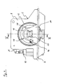
- the windlass of the submarine according to the invention has a foundation 2.
- This foundation 2 has a frame-shaped base plate 4, which is open to a longitudinal side. Accordingly, the base plate has a longitudinal leg, at each of whose two ends a transverse limb protrudes normal to the alignment of the longitudinal limb.
- the base plate 4 is used to attach the windlass on a boat-side foundation.
- a plurality of holes 6 are formed on the base plate 4, which serve to receive the screws with which the windlass is bolted to the boat-side foundation.
- a plate 8 and a plate 10 are arranged at a distance therefrom in the region of their transverse legs, wherein the plates 8 and 10 protrude on both flat sides of the base plate 4.
- a circular recess 12 is formed, wherein the recesses 12 have the same diameter and a common center axis A.
- a support member 14 is disposed on the longitudinal strut of the base plate 4, which also extends normal to the flat side of the base plate 4.
- the support member 14 forms a bearing block for a drive shaft 20 of a drive motor 18 of the windlass and has for receiving this drive shaft 20 has a circular recess whose inner diameter substantially corresponds to the outer diameter of the drive shaft 20.
- the drive motor 18 and its drive shaft 20 will be discussed in more detail below.
- a housing part 16 designed as a cast part is flanged to the plate 10 in such a way that it surrounds the recess 12 formed on the plate 10.
- the drive motor 18 is a hydraulic motor in the form of a radial piston motor.
- the housing part 16 carries the drive motor 18 and seals it against seawater.
- two sealing rings 22 are arranged on the front side of the housing part 16, which seal the housing of the drive motor 18 against the housing part 16.
- two sealing rings 24 and a scraper ring 26 are arranged on the inner circumference of an opening of the housing part 18, through which the drive shaft 20 of the drive motor 18 is guided. With the Sealing rings 24, the drive shaft 20 is sealed relative to the housing part 16.
- a sprocket 28 of the windlass is fixed by means of feather keys such that it is arranged in a region between the plate 8 and the support member 14.
- the chain sprocket 28 forms a guide roller for the anchor chain to be fined or lifted, wherein it is bounded by a disc 30 opposite the support member 14, which is part of the sprocket 28, and by a substantially cylindrical drum 32.
- the end face of the drum 32 is aligned with the flat side of the plate 8. Axially, the drum 32 extends through the gap between the plates 8 and 10th
- the drum 32 forms the brake drum of a band brake 34, by means of which the sprocket 28 can be stopped.
- the band brake 34 has a brake band 36 which is placed in the area bounded by the plates 8 and 10 around the outer periphery of the drum 32.
- Via a lever mechanism 38 and thus an effect-connected spring-biased hydraulic cylinder 40 in the form of a Kurzhubzylinders a frictional connection between the drum 32 and the brake band 36 is provided, which can be canceled by the extension of the hydraulic cylinder 40, whereby the band brake 34 can be solved.
- the hydraulic cylinder 40 is mounted on the foundation 2 in the radial direction on the outside of the drum 32.
- a movement sensor 42 is arranged at the motor-side end of the drive shaft 20 and outside the housing of the drive motor 18, a movement sensor 42 is arranged.
- this motion sensor 42 is an absolute rotary encoder, which can independently determine the exact rotational position of the drive shaft 20 and, consequently, the exact position of the guided over the sprocket 28 anchor.
- For protection from the surrounding the windlass seawater of the motion sensor 42 is through a fixed to the front-side outer end of the drive motor 18 housing 44 which in the FIGS. 1 . 2 . 3 and 6 shown partially cut, waterproof encapsulated.
- a motion sensor 46 may be provided in the form of a proximity switch.
- This motion sensor 46 is attached to the support member 14 on the outside of the sprocket 28 bounding disc 30, wherein on the outside of the disc 30 in the circumferential direction a plurality of switching lugs 48 are arranged in the form of metallic plates corresponding to the position of the motion sensor 46.
- the switching lugs 48 In order to be able to determine a definite angular position with the motion sensor 46, the switching lugs 48 have different distances from one another.
- the windlass of the submarine according to the invention is typically equipped with only one motion sensor, ie either a motion sensor 42 disposed on the drive shaft 20 or an outside the chain nut 28 arranged motion sensor 46 is provided.
Landscapes
- Engineering & Computer Science (AREA)
- Mechanical Engineering (AREA)
- Chemical & Material Sciences (AREA)
- Combustion & Propulsion (AREA)
- Ocean & Marine Engineering (AREA)
- Aviation & Aerospace Engineering (AREA)
- Actuator (AREA)
- Connection Of Motors, Electrical Generators, Mechanical Devices, And The Like (AREA)
- Electric Cable Installation (AREA)
- Motor Or Generator Frames (AREA)
- Braking Arrangements (AREA)
- Wind Motors (AREA)
- Earth Drilling (AREA)
Applications Claiming Priority (1)
| Application Number | Priority Date | Filing Date | Title |
|---|---|---|---|
| DE102008027351A DE102008027351A1 (de) | 2008-06-07 | 2008-06-07 | Unterseeboot |
Publications (3)
| Publication Number | Publication Date |
|---|---|
| EP2130759A2 true EP2130759A2 (fr) | 2009-12-09 |
| EP2130759A3 EP2130759A3 (fr) | 2011-11-02 |
| EP2130759B1 EP2130759B1 (fr) | 2012-07-25 |
Family
ID=41076723
Family Applications (1)
| Application Number | Title | Priority Date | Filing Date |
|---|---|---|---|
| EP09007262A Active EP2130759B1 (fr) | 2008-06-07 | 2009-05-30 | Submersible |
Country Status (5)
| Country | Link |
|---|---|
| EP (1) | EP2130759B1 (fr) |
| KR (1) | KR101181287B1 (fr) |
| DE (1) | DE102008027351A1 (fr) |
| ES (1) | ES2390806T3 (fr) |
| PT (1) | PT2130759E (fr) |
Cited By (3)
| Publication number | Priority date | Publication date | Assignee | Title |
|---|---|---|---|---|
| CN103507920A (zh) * | 2012-06-29 | 2014-01-15 | 大连船舶重工集团有限公司 | 船上基于加强结构的止链器 |
| WO2019166674A1 (fr) * | 2018-03-02 | 2019-09-06 | Vicinay Cadenas S.A. | Tendeur de ligne de fond d'une structure flottante |
| CN117023302A (zh) * | 2023-09-02 | 2023-11-10 | 浙江万通重工有限公司 | 锚绞组合机监控装置 |
Families Citing this family (6)
| Publication number | Priority date | Publication date | Assignee | Title |
|---|---|---|---|---|
| DE102010004548B4 (de) * | 2010-01-14 | 2014-09-25 | Thyssenkrupp Marine Systems Gmbh | Verfahren zum Betrieb eines hydraulischen Systems eines Unterseebootes und Unterseeboot mit einer Hydraulikanlage zur Durchführung des Verfahrens |
| DE102012014463B4 (de) * | 2012-07-18 | 2017-05-04 | Macgregor Hatlapa Gmbh & Co. Kg | Ankerwinde mit handbetätigter Spindelbandbremse |
| CN110950258A (zh) * | 2019-12-18 | 2020-04-03 | 宿州市龙兴机械制造有限公司 | 一种组装一体式调度绞车 |
| CN111409772B (zh) * | 2020-04-02 | 2022-01-11 | 上海电力大学 | 一种便于安装型锚绞机及其安装工艺 |
| WO2025099606A1 (fr) * | 2023-11-07 | 2025-05-15 | Manson Anchors Limited | Système d'ancre de coque |
| WO2026033083A1 (fr) * | 2024-08-07 | 2026-02-12 | Lewmar Limited | Appareil d'ancrage |
Family Cites Families (7)
| Publication number | Priority date | Publication date | Assignee | Title |
|---|---|---|---|---|
| US3125975A (en) * | 1964-03-24 | Submergible hull propulsion and control system | ||
| DD37833A1 (fr) * | 1965-04-05 | |||
| DE2146586C3 (de) * | 1971-09-17 | 1981-12-17 | G.L. Rexroth Gmbh, 8770 Lohr | Mit einer Konstantzug-Regelung versehener hydrostatischer Antrieb |
| US4153001A (en) | 1977-04-05 | 1979-05-08 | Krasberg Alan R | Manned submarine |
| NL7902547A (nl) * | 1978-04-04 | 1979-10-08 | Vickers Shipbuilding Group Ltd | Liermechanismen. |
| FR2852917B1 (fr) | 2003-03-26 | 2005-06-24 | Saipem Sa | Receptacle a compartiments etanches et procede de mise en place pour recuperer des effluents polluants d'une epave |
| DE10349591B4 (de) * | 2003-10-24 | 2007-11-22 | Howaldtswerke-Deutsche Werft Gmbh | Unterseeboot |
-
2008
- 2008-06-07 DE DE102008027351A patent/DE102008027351A1/de not_active Withdrawn
-
2009
- 2009-05-30 EP EP09007262A patent/EP2130759B1/fr active Active
- 2009-05-30 ES ES09007262T patent/ES2390806T3/es active Active
- 2009-05-30 PT PT09007262T patent/PT2130759E/pt unknown
- 2009-06-03 KR KR1020090049152A patent/KR101181287B1/ko active Active
Cited By (6)
| Publication number | Priority date | Publication date | Assignee | Title |
|---|---|---|---|---|
| CN103507920A (zh) * | 2012-06-29 | 2014-01-15 | 大连船舶重工集团有限公司 | 船上基于加强结构的止链器 |
| CN103507920B (zh) * | 2012-06-29 | 2016-03-30 | 大连船舶重工集团有限公司 | 船上基于加强结构的止链器 |
| WO2019166674A1 (fr) * | 2018-03-02 | 2019-09-06 | Vicinay Cadenas S.A. | Tendeur de ligne de fond d'une structure flottante |
| US11008072B2 (en) | 2018-03-02 | 2021-05-18 | Vicinay Cadenas, S.A. | Tensioner of a mooring line of a floating structure |
| EP4242094A3 (fr) * | 2018-03-02 | 2023-11-08 | Vicinay Mooring Connectors, S.A. | Tendeur de ligne de fond d'une structure flottante |
| CN117023302A (zh) * | 2023-09-02 | 2023-11-10 | 浙江万通重工有限公司 | 锚绞组合机监控装置 |
Also Published As
| Publication number | Publication date |
|---|---|
| ES2390806T3 (es) | 2012-11-16 |
| KR20090127225A (ko) | 2009-12-10 |
| DE102008027351A1 (de) | 2009-12-10 |
| PT2130759E (pt) | 2012-09-27 |
| EP2130759B1 (fr) | 2012-07-25 |
| KR101181287B1 (ko) | 2012-09-11 |
| EP2130759A3 (fr) | 2011-11-02 |
Similar Documents
| Publication | Publication Date | Title |
|---|---|---|
| EP2130759B1 (fr) | Submersible | |
| EP1032773B1 (fr) | Frein a disque a actionnement electromecanique | |
| EP3429920B1 (fr) | Entraînement linéaire pour l'appareil à gouverner d'un navire | |
| EP3317222B1 (fr) | Système de treuil de levage | |
| DE102016205794A1 (de) | Antriebseinheit für eine Aufzugsanlage | |
| EP1170518B1 (fr) | Unité de palier verrouillable | |
| WO2014101910A2 (fr) | Dispositif d'entraînement pour l'accouplement pivotant d'un élément d'une installation ou d'une machine | |
| DE202015101779U1 (de) | Permanentmagnet-Synchrondirektantrieb-Hebevorrichtung mit einem einstufigen Zahnrad | |
| EP0949743A2 (fr) | Machine électrique, notamment pour dispositif d'entraínement pour ascenseur | |
| EP4045807A1 (fr) | Frein à disque électromécanique doté d'un actionneur de frein de stationnement pour véhicules automobiles | |
| WO2000031432A1 (fr) | Frein pour reglage du jeu | |
| WO2002065006A1 (fr) | Dispositif d'actionnement destine en particulier a un systeme de restricteur | |
| DE102006052767B4 (de) | Außenläufermotor mit Bremse | |
| EP2662278B1 (fr) | Dispositif de pivotement pour une nacelle à hélice de bateau | |
| EP1069068A1 (fr) | Entraínement compact pour un ascenseur | |
| DE102009029877A1 (de) | Torquemotor mit Brems- und/oder Halteeinrichtung | |
| DE102012220920B3 (de) | Unterseeboot | |
| DE10232421C1 (de) | Hydraulischer Drehmotor mit Kabeldurchführung sowie Kran mit einem derartigen Drehmotor | |
| DE19903409C1 (de) | Getriebelose Aufzugsmaschine mit einem Synchron-Außenläufermotor | |
| EP3348764B1 (fr) | Dispositif d'actionnement au moins partiellement automatique d'un vantail de porte | |
| DE102011102904B4 (de) | Bremssystem | |
| WO2006094494A1 (fr) | Mecanisme d'entrainement de realisation compacte, sans engrenage de transmission et dans un mode a rotor exterieur d'un engin de levage, | |
| EP3589858B1 (fr) | Frein de grande éolienne | |
| EP1431233B1 (fr) | Entrainement hydraulique à câble pour ascenseurs | |
| DE102011079492A1 (de) | Antriebsvorrichtung für ein Flurförderzeug |
Legal Events
| Date | Code | Title | Description |
|---|---|---|---|
| PUAI | Public reference made under article 153(3) epc to a published international application that has entered the european phase |
Free format text: ORIGINAL CODE: 0009012 |
|
| AK | Designated contracting states |
Kind code of ref document: A2 Designated state(s): AT BE BG CH CY CZ DE DK EE ES FI FR GB GR HR HU IE IS IT LI LT LU LV MC MK MT NL NO PL PT RO SE SI SK TR |
|
| PUAL | Search report despatched |
Free format text: ORIGINAL CODE: 0009013 |
|
| AK | Designated contracting states |
Kind code of ref document: A3 Designated state(s): AT BE BG CH CY CZ DE DK EE ES FI FR GB GR HR HU IE IS IT LI LT LU LV MC MK MT NL NO PL PT RO SE SI SK TR |
|
| AX | Request for extension of the european patent |
Extension state: AL BA RS |
|
| RIC1 | Information provided on ipc code assigned before grant |
Ipc: B63G 8/00 20060101AFI20110926BHEP Ipc: B63B 21/16 20060101ALI20110926BHEP Ipc: B63B 21/22 20060101ALI20110926BHEP |
|
| 17P | Request for examination filed |
Effective date: 20111012 |
|
| GRAP | Despatch of communication of intention to grant a patent |
Free format text: ORIGINAL CODE: EPIDOSNIGR1 |
|
| GRAS | Grant fee paid |
Free format text: ORIGINAL CODE: EPIDOSNIGR3 |
|
| GRAA | (expected) grant |
Free format text: ORIGINAL CODE: 0009210 |
|
| AK | Designated contracting states |
Kind code of ref document: B1 Designated state(s): AT BE BG CH CY CZ DE DK EE ES FI FR GB GR HR HU IE IS IT LI LT LU LV MC MK MT NL NO PL PT RO SE SI SK TR |
|
| REG | Reference to a national code |
Ref country code: GB Ref legal event code: FG4D Free format text: NOT ENGLISH |
|
| REG | Reference to a national code |
Ref country code: CH Ref legal event code: EP |
|
| REG | Reference to a national code |
Ref country code: AT Ref legal event code: REF Ref document number: 567582 Country of ref document: AT Kind code of ref document: T Effective date: 20120815 Ref country code: IE Ref legal event code: FG4D Free format text: LANGUAGE OF EP DOCUMENT: GERMAN |
|
| REG | Reference to a national code |
Ref country code: DE Ref legal event code: R096 Ref document number: 502009004148 Country of ref document: DE Effective date: 20120920 |
|
| REG | Reference to a national code |
Ref country code: PT Ref legal event code: SC4A Free format text: AVAILABILITY OF NATIONAL TRANSLATION Effective date: 20120921 |
|
| REG | Reference to a national code |
Ref country code: SE Ref legal event code: TRGR |
|
| REG | Reference to a national code |
Ref country code: GR Ref legal event code: EP Ref document number: 20120402054 Country of ref document: GR Effective date: 20120915 |
|
| REG | Reference to a national code |
Ref country code: ES Ref legal event code: FG2A Ref document number: 2390806 Country of ref document: ES Kind code of ref document: T3 Effective date: 20121116 |
|
| REG | Reference to a national code |
Ref country code: NL Ref legal event code: T3 |
|
| REG | Reference to a national code |
Ref country code: LT Ref legal event code: MG4D Effective date: 20120725 |
|
| PG25 | Lapsed in a contracting state [announced via postgrant information from national office to epo] |
Ref country code: FI Free format text: LAPSE BECAUSE OF FAILURE TO SUBMIT A TRANSLATION OF THE DESCRIPTION OR TO PAY THE FEE WITHIN THE PRESCRIBED TIME-LIMIT Effective date: 20120725 Ref country code: HR Free format text: LAPSE BECAUSE OF FAILURE TO SUBMIT A TRANSLATION OF THE DESCRIPTION OR TO PAY THE FEE WITHIN THE PRESCRIBED TIME-LIMIT Effective date: 20120725 Ref country code: NO Free format text: LAPSE BECAUSE OF FAILURE TO SUBMIT A TRANSLATION OF THE DESCRIPTION OR TO PAY THE FEE WITHIN THE PRESCRIBED TIME-LIMIT Effective date: 20121025 Ref country code: LT Free format text: LAPSE BECAUSE OF FAILURE TO SUBMIT A TRANSLATION OF THE DESCRIPTION OR TO PAY THE FEE WITHIN THE PRESCRIBED TIME-LIMIT Effective date: 20120725 Ref country code: IS Free format text: LAPSE BECAUSE OF FAILURE TO SUBMIT A TRANSLATION OF THE DESCRIPTION OR TO PAY THE FEE WITHIN THE PRESCRIBED TIME-LIMIT Effective date: 20121125 Ref country code: CY Free format text: LAPSE BECAUSE OF FAILURE TO SUBMIT A TRANSLATION OF THE DESCRIPTION OR TO PAY THE FEE WITHIN THE PRESCRIBED TIME-LIMIT Effective date: 20120725 |
|
| REG | Reference to a national code |
Ref country code: DE Ref legal event code: R082 Ref document number: 502009004148 Country of ref document: DE Representative=s name: PATENTANWAELTE VOLLMANN & HEMMER, DE |
|
| PG25 | Lapsed in a contracting state [announced via postgrant information from national office to epo] |
Ref country code: SI Free format text: LAPSE BECAUSE OF FAILURE TO SUBMIT A TRANSLATION OF THE DESCRIPTION OR TO PAY THE FEE WITHIN THE PRESCRIBED TIME-LIMIT Effective date: 20120725 Ref country code: LV Free format text: LAPSE BECAUSE OF FAILURE TO SUBMIT A TRANSLATION OF THE DESCRIPTION OR TO PAY THE FEE WITHIN THE PRESCRIBED TIME-LIMIT Effective date: 20120725 Ref country code: PL Free format text: LAPSE BECAUSE OF FAILURE TO SUBMIT A TRANSLATION OF THE DESCRIPTION OR TO PAY THE FEE WITHIN THE PRESCRIBED TIME-LIMIT Effective date: 20120725 |
|
| RAP2 | Party data changed (patent owner data changed or rights of a patent transferred) |
Owner name: THYSSENKRUPP MARINE SYSTEMS GMBH |
|
| REG | Reference to a national code |
Ref country code: NL Ref legal event code: SD Effective date: 20130312 |
|
| REG | Reference to a national code |
Ref country code: DE Ref legal event code: R082 Ref document number: 502009004148 Country of ref document: DE Representative=s name: PATENTANWAELTE VOLLMANN & HEMMER, DE Effective date: 20130206 Ref country code: DE Ref legal event code: R081 Ref document number: 502009004148 Country of ref document: DE Owner name: THYSSENKRUPP MARINE SYSTEMS GMBH, DE Free format text: FORMER OWNER: HOWALDTSWERKE-DEUTSCHE WERFT GMBH, 24143 KIEL, DE Effective date: 20130206 |
|
| REG | Reference to a national code |
Ref country code: FR Ref legal event code: CD Owner name: THYSSENKRUPP MARINE SYSTEMS GMBH Effective date: 20130313 |
|
| REG | Reference to a national code |
Ref country code: NL Ref legal event code: TD Effective date: 20130417 |
|
| PG25 | Lapsed in a contracting state [announced via postgrant information from national office to epo] |
Ref country code: EE Free format text: LAPSE BECAUSE OF FAILURE TO SUBMIT A TRANSLATION OF THE DESCRIPTION OR TO PAY THE FEE WITHIN THE PRESCRIBED TIME-LIMIT Effective date: 20120725 Ref country code: DK Free format text: LAPSE BECAUSE OF FAILURE TO SUBMIT A TRANSLATION OF THE DESCRIPTION OR TO PAY THE FEE WITHIN THE PRESCRIBED TIME-LIMIT Effective date: 20120725 Ref country code: RO Free format text: LAPSE BECAUSE OF FAILURE TO SUBMIT A TRANSLATION OF THE DESCRIPTION OR TO PAY THE FEE WITHIN THE PRESCRIBED TIME-LIMIT Effective date: 20120725 Ref country code: CZ Free format text: LAPSE BECAUSE OF FAILURE TO SUBMIT A TRANSLATION OF THE DESCRIPTION OR TO PAY THE FEE WITHIN THE PRESCRIBED TIME-LIMIT Effective date: 20120725 |
|
| PG25 | Lapsed in a contracting state [announced via postgrant information from national office to epo] |
Ref country code: SK Free format text: LAPSE BECAUSE OF FAILURE TO SUBMIT A TRANSLATION OF THE DESCRIPTION OR TO PAY THE FEE WITHIN THE PRESCRIBED TIME-LIMIT Effective date: 20120725 |
|
| PGFP | Annual fee paid to national office [announced via postgrant information from national office to epo] |
Ref country code: GR Payment date: 20130328 Year of fee payment: 5 |
|
| PLBE | No opposition filed within time limit |
Free format text: ORIGINAL CODE: 0009261 |
|
| STAA | Information on the status of an ep patent application or granted ep patent |
Free format text: STATUS: NO OPPOSITION FILED WITHIN TIME LIMIT |
|
| PGFP | Annual fee paid to national office [announced via postgrant information from national office to epo] |
Ref country code: PT Payment date: 20130312 Year of fee payment: 5 |
|
| 26N | No opposition filed |
Effective date: 20130426 |
|
| PG25 | Lapsed in a contracting state [announced via postgrant information from national office to epo] |
Ref country code: BG Free format text: LAPSE BECAUSE OF FAILURE TO SUBMIT A TRANSLATION OF THE DESCRIPTION OR TO PAY THE FEE WITHIN THE PRESCRIBED TIME-LIMIT Effective date: 20121025 |
|
| REG | Reference to a national code |
Ref country code: DE Ref legal event code: R097 Ref document number: 502009004148 Country of ref document: DE Effective date: 20130426 |
|
| PGFP | Annual fee paid to national office [announced via postgrant information from national office to epo] |
Ref country code: DE Payment date: 20130711 Year of fee payment: 5 |
|
| BERE | Be: lapsed |
Owner name: HOWALDTSWERKE-DEUTSCHE WERFT G.M.B.H. Effective date: 20130531 |
|
| PG25 | Lapsed in a contracting state [announced via postgrant information from national office to epo] |
Ref country code: MC Free format text: LAPSE BECAUSE OF FAILURE TO SUBMIT A TRANSLATION OF THE DESCRIPTION OR TO PAY THE FEE WITHIN THE PRESCRIBED TIME-LIMIT Effective date: 20120725 |
|
| REG | Reference to a national code |
Ref country code: CH Ref legal event code: PL |
|
| PG25 | Lapsed in a contracting state [announced via postgrant information from national office to epo] |
Ref country code: LI Free format text: LAPSE BECAUSE OF NON-PAYMENT OF DUE FEES Effective date: 20130531 Ref country code: CH Free format text: LAPSE BECAUSE OF NON-PAYMENT OF DUE FEES Effective date: 20130531 |
|
| REG | Reference to a national code |
Ref country code: IE Ref legal event code: MM4A |
|
| PG25 | Lapsed in a contracting state [announced via postgrant information from national office to epo] |
Ref country code: BE Free format text: LAPSE BECAUSE OF NON-PAYMENT OF DUE FEES Effective date: 20130531 |
|
| PG25 | Lapsed in a contracting state [announced via postgrant information from national office to epo] |
Ref country code: IE Free format text: LAPSE BECAUSE OF NON-PAYMENT OF DUE FEES Effective date: 20130530 |
|
| REG | Reference to a national code |
Ref country code: DE Ref legal event code: R119 Ref document number: 502009004148 Country of ref document: DE |
|
| REG | Reference to a national code |
Ref country code: PT Ref legal event code: MM4A Free format text: LAPSE DUE TO NON-PAYMENT OF FEES Effective date: 20141202 |
|
| PG25 | Lapsed in a contracting state [announced via postgrant information from national office to epo] |
Ref country code: GR Free format text: LAPSE BECAUSE OF NON-PAYMENT OF DUE FEES Effective date: 20141203 Ref country code: PT Free format text: LAPSE BECAUSE OF NON-PAYMENT OF DUE FEES Effective date: 20141202 |
|
| REG | Reference to a national code |
Ref country code: GR Ref legal event code: ML Ref document number: 20120402054 Country of ref document: GR Effective date: 20141203 |
|
| PG25 | Lapsed in a contracting state [announced via postgrant information from national office to epo] |
Ref country code: MT Free format text: LAPSE BECAUSE OF FAILURE TO SUBMIT A TRANSLATION OF THE DESCRIPTION OR TO PAY THE FEE WITHIN THE PRESCRIBED TIME-LIMIT Effective date: 20120725 |
|
| REG | Reference to a national code |
Ref country code: DE Ref legal event code: R119 Ref document number: 502009004148 Country of ref document: DE Effective date: 20141202 |
|
| PG25 | Lapsed in a contracting state [announced via postgrant information from national office to epo] |
Ref country code: DE Free format text: LAPSE BECAUSE OF NON-PAYMENT OF DUE FEES Effective date: 20141202 |
|
| REG | Reference to a national code |
Ref country code: AT Ref legal event code: MM01 Ref document number: 567582 Country of ref document: AT Kind code of ref document: T Effective date: 20140530 |
|
| PG25 | Lapsed in a contracting state [announced via postgrant information from national office to epo] |
Ref country code: LU Free format text: LAPSE BECAUSE OF NON-PAYMENT OF DUE FEES Effective date: 20130530 Ref country code: MK Free format text: LAPSE BECAUSE OF FAILURE TO SUBMIT A TRANSLATION OF THE DESCRIPTION OR TO PAY THE FEE WITHIN THE PRESCRIBED TIME-LIMIT Effective date: 20120725 Ref country code: HU Free format text: LAPSE BECAUSE OF FAILURE TO SUBMIT A TRANSLATION OF THE DESCRIPTION OR TO PAY THE FEE WITHIN THE PRESCRIBED TIME-LIMIT; INVALID AB INITIO Effective date: 20090530 |
|
| PG25 | Lapsed in a contracting state [announced via postgrant information from national office to epo] |
Ref country code: AT Free format text: LAPSE BECAUSE OF NON-PAYMENT OF DUE FEES Effective date: 20140530 |
|
| REG | Reference to a national code |
Ref country code: FR Ref legal event code: PLFP Year of fee payment: 8 |
|
| REG | Reference to a national code |
Ref country code: FR Ref legal event code: PLFP Year of fee payment: 9 |
|
| REG | Reference to a national code |
Ref country code: FR Ref legal event code: PLFP Year of fee payment: 10 |
|
| PGFP | Annual fee paid to national office [announced via postgrant information from national office to epo] |
Ref country code: NL Payment date: 20250521 Year of fee payment: 17 |
|
| PGFP | Annual fee paid to national office [announced via postgrant information from national office to epo] |
Ref country code: GB Payment date: 20250521 Year of fee payment: 17 Ref country code: ES Payment date: 20250627 Year of fee payment: 17 |
|
| PGFP | Annual fee paid to national office [announced via postgrant information from national office to epo] |
Ref country code: IT Payment date: 20250527 Year of fee payment: 17 |
|
| PGFP | Annual fee paid to national office [announced via postgrant information from national office to epo] |
Ref country code: FR Payment date: 20250528 Year of fee payment: 17 |
|
| PGFP | Annual fee paid to national office [announced via postgrant information from national office to epo] |
Ref country code: TR Payment date: 20250526 Year of fee payment: 17 |
|
| PGFP | Annual fee paid to national office [announced via postgrant information from national office to epo] |
Ref country code: SE Payment date: 20250521 Year of fee payment: 17 |