EP2130809A1 - Verfahren zur herstellung einer keramikwabenstruktur - Google Patents
Verfahren zur herstellung einer keramikwabenstruktur Download PDFInfo
- Publication number
- EP2130809A1 EP2130809A1 EP08722516A EP08722516A EP2130809A1 EP 2130809 A1 EP2130809 A1 EP 2130809A1 EP 08722516 A EP08722516 A EP 08722516A EP 08722516 A EP08722516 A EP 08722516A EP 2130809 A1 EP2130809 A1 EP 2130809A1
- Authority
- EP
- European Patent Office
- Prior art keywords
- ceramic honeycomb
- coating material
- outer peripheral
- honeycomb body
- thickness
- Prior art date
- Legal status (The legal status is an assumption and is not a legal conclusion. Google has not performed a legal analysis and makes no representation as to the accuracy of the status listed.)
- Granted
Links
Images



Classifications
-
- C—CHEMISTRY; METALLURGY
- C04—CEMENTS; CONCRETE; ARTIFICIAL STONE; CERAMICS; REFRACTORIES
- C04B—LIME, MAGNESIA; SLAG; CEMENTS; COMPOSITIONS THEREOF, e.g. MORTARS, CONCRETE OR LIKE BUILDING MATERIALS; ARTIFICIAL STONE; CERAMICS; REFRACTORIES; TREATMENT OF NATURAL STONE
- C04B41/00—After-treatment of mortars, concrete, artificial stone or ceramics; Treatment of natural stone
- C04B41/45—Coating or impregnating, e.g. injection in masonry, partial coating of green or fired ceramics, organic coating compositions for adhering together two concrete elements
- C04B41/50—Coating or impregnating, e.g. injection in masonry, partial coating of green or fired ceramics, organic coating compositions for adhering together two concrete elements with inorganic materials
- C04B41/5024—Silicates
-
- C—CHEMISTRY; METALLURGY
- C04—CEMENTS; CONCRETE; ARTIFICIAL STONE; CERAMICS; REFRACTORIES
- C04B—LIME, MAGNESIA; SLAG; CEMENTS; COMPOSITIONS THEREOF, e.g. MORTARS, CONCRETE OR LIKE BUILDING MATERIALS; ARTIFICIAL STONE; CERAMICS; REFRACTORIES; TREATMENT OF NATURAL STONE
- C04B41/00—After-treatment of mortars, concrete, artificial stone or ceramics; Treatment of natural stone
- C04B41/009—After-treatment of mortars, concrete, artificial stone or ceramics; Treatment of natural stone characterised by the material treated
-
- C—CHEMISTRY; METALLURGY
- C04—CEMENTS; CONCRETE; ARTIFICIAL STONE; CERAMICS; REFRACTORIES
- C04B—LIME, MAGNESIA; SLAG; CEMENTS; COMPOSITIONS THEREOF, e.g. MORTARS, CONCRETE OR LIKE BUILDING MATERIALS; ARTIFICIAL STONE; CERAMICS; REFRACTORIES; TREATMENT OF NATURAL STONE
- C04B41/00—After-treatment of mortars, concrete, artificial stone or ceramics; Treatment of natural stone
- C04B41/80—After-treatment of mortars, concrete, artificial stone or ceramics; Treatment of natural stone of only ceramics
- C04B41/81—Coating or impregnation
- C04B41/85—Coating or impregnation with inorganic materials
- C04B41/87—Ceramics
-
- C—CHEMISTRY; METALLURGY
- C04—CEMENTS; CONCRETE; ARTIFICIAL STONE; CERAMICS; REFRACTORIES
- C04B—LIME, MAGNESIA; SLAG; CEMENTS; COMPOSITIONS THEREOF, e.g. MORTARS, CONCRETE OR LIKE BUILDING MATERIALS; ARTIFICIAL STONE; CERAMICS; REFRACTORIES; TREATMENT OF NATURAL STONE
- C04B2111/00—Mortars, concrete or artificial stone or mixtures to prepare them, characterised by specific function, property or use
- C04B2111/00474—Uses not provided for elsewhere in C04B2111/00
- C04B2111/00793—Uses not provided for elsewhere in C04B2111/00 as filters or diaphragms
-
- C—CHEMISTRY; METALLURGY
- C04—CEMENTS; CONCRETE; ARTIFICIAL STONE; CERAMICS; REFRACTORIES
- C04B—LIME, MAGNESIA; SLAG; CEMENTS; COMPOSITIONS THEREOF, e.g. MORTARS, CONCRETE OR LIKE BUILDING MATERIALS; ARTIFICIAL STONE; CERAMICS; REFRACTORIES; TREATMENT OF NATURAL STONE
- C04B2111/00—Mortars, concrete or artificial stone or mixtures to prepare them, characterised by specific function, property or use
- C04B2111/00474—Uses not provided for elsewhere in C04B2111/00
- C04B2111/0081—Uses not provided for elsewhere in C04B2111/00 as catalysts or catalyst carriers
Definitions
- the present invention relates to a method for producing a ceramic honeycomb structure, particularly to a method for producing a ceramic honeycomb structure by forming an outer peripheral wall on an outer peripheral surface of the ceramic honeycomb body.
- exhaust-gas-cleaning catalytic converters and particulate-matter-capturing ceramic honeycomb filters comprising ceramic honeycomb structures are used.
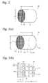
- a conventional ceramic honeycomb structure 20 comprises large numbers of flow paths 14 defined by perpendicularly crossing cell walls 13 and an outer peripheral wall 21, usually having a substantially circular or elliptical vertical cross section in a flow path direction.
- the outer peripheral wall 21 of the ceramic honeycomb structure 20 is held by a grip member (not shown) formed by a metal mesh, a ceramic mat, etc. in a metal container (not shown).
- the ceramic honeycomb structure 20 is produced by the steps of (1) mixing and blending starting materials comprising ceramic materials such as cordierite powder, a molding aid, a pore-forming material, etc. with water to prepare a moldable ceramic material, (2) extruding the moldable ceramic material through a honeycomb-shaped die to produce a green ceramic honeycomb body integrally comprising an outer peripheral wall 21 and cell walls 13, and (3) drying and sintering the green body.
- Such steps provides a ceramic honeycomb structure 20 having predetermined shape and strength, with cell walls 13 having fine pores.
- Used for filters for cleaning exhaust gases from diesel engines may be large ceramic honeycomb structures 20 of 150 mm or more in outer diameter Da and 150 mm or more in length L with cell walls 13 as thin as 0.2 mm or less, in Fig. 2 .
- green ceramic honeycomb bodies obtained by extruding moldable ceramic materials have such insufficient strength that they are likely deformed with cell walls 13 in edge portions of their outer peripheral walls 21 crushed by their own weight. The sintering of deformed green bodies would not provide ceramic honeycomb structures 20 with predetermined strength.
- JP 5-269388 A discloses a honeycomb structure 10 obtained by filling a coating material 12c comprising cordierite particles and/or ceramic fibers and colloidal oxide (colloidal silica, colloidal alumina, etc.) as main components in grooves 15 of cells 14a on an outer peripheral surface, among large numbers of cells 14 defined by cell walls 13, and drying or sintering it to form an outer peripheral wall 12 having a thickness T on a ceramic honeycomb body 11, such that the honeycomb structure 10 has an outer diameter Dd.
- JP 5-269388 A describes that the outer peripheral wall 12 reinforces an outer peripheral surface 11a, thereby providing the honeycomb structure 10 with excellent heat resistance and thermal shock resistance.
- JP 2002-166404 A proposes a method for producing a ceramic honeycomb structure 10 having a uniform outer size, comprising applying a coating material 12c to an outer peripheral surface 11a of ceramic honeycomb body 11, from which a peripheral portion is removed by machining, using an apparatus shown in Fig. 4(a) , and drying the resultant coating to an outer peripheral wall 12.
- the apparatus shown in Fig. 4(a) comprises center members 42 for sandwiching center portions of both end surfaces 15a, 15b of the ceramic honeycomb body 11, and outer members 41 each surrounding the center member 42 for sandwiching outer portions of both end surfaces 15a, 15b.
- Each center member 42 comprises a planar support plate 42a and a shaft member 42c fixed to the support plate 42a
- each outer member 41 comprises a flat, hollow support plate 41a, a hollow shaft member 41 c fixed to this support plate 41a, and a portion 41 b having an outer diameter Dc larger than the outer diameter Db of the outer peripheral surface 11a of the ceramic honeycomb body 11 for abutting a scraper 43.
- JP 2002-166404 A comprises sandwiching both end surfaces 15a, 15b of the ceramic honeycomb bodies 11 with the sandwiching members 41 a, 42a, abutting the scraper 43 to the outer diameter Dc of the abutting portion, rotating the shaft members 4 1 c, 42c integral with the support plate 41, filling a coating material 12c in a gap defined by the outer peripheral surface 11a of ceramic honeycomb body 11, the support plates 41 and the scraper 43, and drying the coating material 12c applied to the outer peripheral surface to form the outer peripheral wall 12 shown in Fig. 4(b) .
- This reference describes that by providing each sandwiching member with a two-part structure comprising the center member 42 and the outer member 41, the sandwiching members can easily be detached from the ceramic honeycomb body 11 to which the coating material is applied.
- the thickness T of the dried outer peripheral walls 12 formed by the methods described in JP 5-269388 A and JP 2002-166404 A is smaller than the target outer diameter of the ceramic honeycomb structure 10, because the coating material 12c shrinks due to the evaporation of water by drying. Accordingly, the ceramic honeycomb structure 10 is shaken in a metal container during use, resulting in the likelihood of breakage.
- the volume of notches should be increased so that broken peripheral portions and deformed cell walls 13, if any, can be removed. Accordingly,
- the outer diameter Db [see Fig. 4(a) ] before forming the outer peripheral wall 12 may differ from one ceramic honeycomb body 11 to another. Further, when sintering is conducted after removing the peripheral portion from the ceramic honeycomb body 11 by machining, the outer diameter of the ceramic honeycomb body 11 differs more due to expansion and shrinkage in sintering.
- a coating material 12c is applied to the outer peripheral surfaces 11a of ceramic honeycomb bodies 11 having different outer diameters Db, using support plates of a constant size as shown in Fig. 4(a) , coating materials 12c having different thicknesses Tc are formed on ceramic honeycomb bodies 11. Different thicknesses of the coating materials 12c result in difference drying shrinkage degrees, failing to provide ceramic honeycomb structures 10 having constant outer diameters Dd after drying. Particularly when the outer diameter of the honeycomb structure 10 is smaller than the target size, the ceramic honeycomb structure 10 is shaken in a metal container during use, resulting in the likelihood of breakage.
- a coating material 12c cannot fully be applied to the outer peripheral surface 11a of the ceramic honeycomb body 11 near the end surfaces 15a, 15b by the methods of JP 5-269388 A and JP 2002-166404 A , gaps 17 are generated in boundaries 16 between the outer peripheral surface 11a of the dried ceramic honeycomb structure 10 and the coating material 12c as shown in Fig. 4(b) , so that the outer peripheral wall 12 is easily cracked.
- an object of the present invention is to provide a method for forming an outer peripheral wall such that the outer diameter of the resultant ceramic honeycomb structure is equal to a target size, thereby reducing unevenness in the outer diameter. It further prevents gaps from generating in boundaries between the outer peripheral surface of the ceramic honeycomb body and the coating material near both end surfaces, thereby preventing the cracking of the outer peripheral wall.
- the inventors Taking into consideration the shrinkage ratio of a coating material during drying, the inventors have found that it is possible to provide the formed outer peripheral wall with a proper thickness by adjusting the thickness of a coating material applied depending on ceramic honeycomb bodies, thereby providing the ceramic honeycomb structure with a constant outer diameter, and that by making the outer peripheral wall longitudinally longer than the ceramic honeycomb body, the outer peripheral wall can be formed without gaps in boundaries between the outer peripheral surface and the coating material.
- the present invention has been completed based on such finding.
- the method of the present invention for producing a ceramic honeycomb structure comprises applying a coating material to an outer peripheral surface of the ceramic honeycomb body to form an outer peripheral wall, the thickness of the coating material applied being determined from the outer diameter of the ceramic honeycomb body and the drying shrinkage ratio of the coating material, such that the outer diameter of the dried ceramic honeycomb structure is a target outer size ⁇ 1.4 mm.
- the thickness of the coating material is preferably adjusted by a gap between the outer peripheral surface of the ceramic honeycomb body and a scraper disposed outside the ceramic honeycomb body.
- the coating material is preferably applied to the outer peripheral surface and edge portions of end surfaces of the ceramic honeycomb body, to form the outer peripheral wall such that the longitudinal length of the outer peripheral wall is larger than that of the ceramic honeycomb body by 1.4 to 4 times the thickness of the coating material, and to form the end edge walls on the edge portions of end surfaces of the ceramic honeycomb body such that the end edge walls are as wide as 1.2-6 times the thickness of the coating material.
- Another method of the present invention for producing a ceramic honeycomb structure comprising applying a coating material to an outer peripheral surface of the ceramic honeycomb body to form an outer peripheral wall, comprising applying the coating material to the outer peripheral surface and edge portions of end surfaces of the ceramic honeycomb body, to form the outer peripheral wall such that the longitudinal length of the outer peripheral wall is larger than that of the ceramic honeycomb body by 1.4 to 4 times the thickness of the coating material, and to form the end edge walls on the edge portions of end surfaces of the ceramic honeycomb body such that the end edge walls are as wide as 1.2-6 times the thickness of the coating material.
- the outer peripheral wall formed longitudinally longer than the ceramic honeycomb body and the end edge walls formed on the edge portions of end surfaces of the ceramic honeycomb body preferably are removed to the same position as each end surface of the ceramic honeycomb body after drying.
- Fig. 1(a) is a schematic cross-sectional view showing an apparatus for applying a coating material to a ceramic honeycomb body, which is used in the production method of the present invention.
- Fig. 1(b) is an enlarged cross-sectional view showing a portion A of the ceramic honeycomb structure shown in Fig. 1(a) .
- Fig. 1(c) is a schematic cross-sectional view showing an apparatus for applying a coating material to a ceramic honeycomb body, which is used in another production method of the present invention.
- Fig. 1(d) is an enlarged cross-sectional view showing a portion B of the ceramic honeycomb structure shown in Fig. 1(c) .
- Fig. 1(e) is a front view showing an end surface of the ceramic honeycomb structure shown in Fig. 1(c) .
- Fig. 2 is a perspective view showing a conventional ceramic honeycomb structure.
- Fig. 3(a) is a perspective view showing the ceramic honeycomb structure described in JP 5-269388 A .
- Fig. 3(b) is an enlarged front view showing the portion C in Fig. 3(a) .
- Fig. 4(a) is a cross-sectional view showing the apparatus for applying a coating material to a ceramic honeycomb body, which is described in JP 2002-166404 A .
- Fig. 4(b) is an enlarged cross-sectional view showing a portion D of the ceramic honeycomb structure shown in Fig. 4(a) .
- the method of the present invention for producing a ceramic honeycomb structure comprises applying a coating material to an outer peripheral surface of the ceramic honeycomb body to form an outer peripheral wall, coating being conducted from the outer diameter of the ceramic honeycomb body and the drying shrinkage ratio of the coating material, such that the dried ceramic honeycomb structure has a target outer size.
- the thickness Tc of the coating material 12c applied should be changed depending on the ceramic honeycomb bodies 11 to provide the applied and dried ceramic honeycomb structure 10 with an outer diameter set to a predetermined target size Dd 0 . For instance, when the outer diameter Db and target size Dd 0 of the ceramic honeycomb body 11 have large difference, the thickness Tc of the coating material 12c is increased. When the outer diameter Db and target size Dd 0 of the ceramic honeycomb body 11 have small difference, the thickness Tc of the coating material 12c is reduced.
- the applied coating material 12c shrinks by the evaporation of water. Accordingly, if the coating materials 12c had different thicknesses Tc as described above, the dried outer peripheral walls 12 would have different thicknesses T because of different drying shrinkage, resulting in different outer diameters Dd from one ceramic honeycomb body 10 to another. If the outer diameter Dd were larger than the target size Dd 0 , the outer peripheral wall 12 of the ceramic honeycomb structure 10 would likely be subjected to excess pressure when received in a metal container, resulting in cracking. If the outer diameter Dd were smaller than the target size Dd 0 , the ceramic honeycomb structure 10 would likely be shaken in a metal container during use, resulting in breakage.
- the thickness Tc of the coating material is determined taking into consideration the drying shrinkage ratio of the coating material, such that the ceramic honeycomb structure has a target size Dd 0 after drying. Because the coating material shrinks by drying as described above, shrinkage should be taken into consideration to make the thickness Tc of the coating material 12c applied larger than T, wherein T is the thickness of the dried outer peripheral wall, which corresponds to one-half of the difference between the outer diameter Db and target size Dd 0 of the ceramic honeycomb body 11.
- the thickness Tc of the coating material 12c is T x [1/(1 - S)] to form an outer peripheral wall having thickness T.
- the ceramic honeycomb structure 10 can have reduced unevenness in outer diameter.
- the difference between the target size Dd 0 and the final outer diameter Dd of the ceramic honeycomb structure is preferably from -1.4 mm to +1.4 mm.
- the drying shrinkage ratio of the coating material 12c is determined by (Tc - T)/Tc, wherein Tc is the thickness of coating material 12c applied, and T is the thickness of the dried outer peripheral wall 12.
- the thickness of a coating material 12c applied is preferably adjusted by a gap between the outer peripheral surface of the ceramic honeycomb body 11 and a scraper 3 disposed outside the ceramic honeycomb body 11.
- a coating material 12c is applied to the outer peripheral surface 11a of the ceramic honeycomb body 11, such that gaps defined by the outer peripheral surface 11a of the ceramic honeycomb body 11, the support plates 1 and the scraper 3 are filled with the coating material 12c.
- the thickness of coating material 12c which is determined by distance between the outer peripheral surface 11a of the ceramic honeycomb body 11 and the scraper 3, can be adjusted by using support plates 1 having different diameters.
- a coating material 12c is preferably applied not only to the outer peripheral surface 11a of the ceramic honeycomb body 11 but also to edge portions of the end surfaces 15a, 15b, thereby forming an outer peripheral wall 12 longitudinally longer than the ceramic honeycomb body 11, and end edge walls 18 on edge portions of the end surfaces 15a, 15b of the ceramic honeycomb body 11.
- gaps 17 are not generated in boundaries 16 between the outer peripheral surface 11a near the end surfaces 15a, 15b and the coating material 12c, thereby preventing the cracking of the outer peripheral wall 12 by shock, etc.
- the end edge walls 18 are preferably removed from the end surfaces 15a, 15b after drying, thereby providing a ceramic honeycomb structure 10 without gaps 17 in boundaries 16 between the outer peripheral surface 11a near the end surfaces 15a, 15b of the ceramic honeycomb body 11 and the coating material 12c.
- the difference (b 1 + b 2 ) between the longitudinal length of the outer peripheral wall 12 and the longitudinal length L of the ceramic honeycomb body 11 is preferably 1.4 to 4 times the thickness Tc of the coating material 12c applied.
- the width d of the end edge walls 18 formed on the edge portions of the end surfaces 15a, 15b of the ceramic honeycomb body 11 is preferably 1.2-6 times the thickness Tc of the coating material applied. With the end edge walls 18 formed in such shape, gaps 17 can be effectively prevented from generating in boundaries 16 between the outer peripheral surface 11a near end surfaces 15a, 15b of the ceramic honeycomb body 11 and the coating material 12c.
- the difference (b 1 + b 2 ) is less than 1.4 times the thickness Tc of the coating material applied, the end edge walls 18 are too thin, resulting in gaps 17 generated during drying in boundaries 16 between the outer peripheral surface 11a and the coating material 12c, making it likely that the outer peripheral wall 12 are cracked.
- the difference (b 1 + b 2 ) exceeds 4 times the thickness Tc, an excess coating material 12c applied to the edge portions of the end surfaces 15a, 15b should be removed.
- the difference (b 1 + b 2 ) is more preferably 1.4-3.5 times, further preferably 1.4-3 times, the thickness Tc of the coating material 12c applied.
- the width d of the end edge walls 18 When the width d of the end edge walls 18 is less than 1.2 times the thickness Tc of the coating material 12c applied, gaps tend to be formed in boundaries 16 between the outer peripheral surface 11a and the coating material 12c, making it likely that the outer peripheral wall 12 are cracked. On the other hand, when the width d of the end edge walls 18 exceeds 6 times the thickness Tc, part of cells 14 are clogged by the coating material 12c applied to the edge portions of the end surfaces 15a, 15b.
- the width d of the end edge walls 18 are more preferably 1.5-5 times, further preferably 1.7-4 times, the thickness Tc of the coating material applied.
- notches P in portions 1b of the support plates 1 abutting the scraper 3 are filled with the coating material 12c, so that the coating material 12c are applied to the end surfaces 15a, 15b of the ceramic honeycomb body 11.
- the end edge walls 18 are formed on the edge portions of the end surfaces 15a, 15b of the ceramic honeycomb body 11. The end edge walls 18 are preferably removed from the end surfaces 15a, 15b after drying.
- the notches P preferably have widths b 1 , b 2 and the width d, which are 0.7-2 times and 1.2-6 times, respectively, the thickness Tc of the coating material 12c. Because such size permits the coating material 12c applied to fully fill the notches P, gaps can be prevented from generating in boundaries 16 between the outer peripheral surface 11a of the ceramic honeycomb body 11 and the coating material 12c, resulting in a ceramic honeycomb structure 10 having a cracking-resistant outer peripheral wall 12.
- widths b 1 , b 2 of the notches P are less than 0.7 times the thickness Tc of the coating material 12c, a coating material is not easily applied to the edge portions of the end surfaces 15a, 15b of the ceramic honeycomb body 11, resulting in gaps formed in boundaries 16 between the outer peripheral surface 11a and the coating material 12c.
- widths b 1 , b 2 of the notches P exceed 2 times the thickness Tc of the coating material applied, an excess coating material 12c applied to the edge portions of the end surfaces 15a, 15b should be removed.
- the width d of the notches P is less than 1.2 times the thickness Tc of the coating material applied, a coating material is not easily applied to the edge portions of the end surfaces 15a, 15b of the ceramic honeycomb body 11, resulting in gaps formed in boundaries between the outer peripheral surface 11a and the coating material 12c.
- the width d of the notches P exceeds 6 times the thickness Tc of the coating material applied, part of cells are clogged by a coating material 12c applied to the edge portions of the end surfaces 15a, 15b.
- the viscosity of the coating material is preferably 20 Pa ⁇ s or more.
- the coating material having a viscosity of 20 Pa ⁇ s or more can form an outer peripheral wall 12 and end edge walls 18 having high strength.
- the viscosity of the coating material is less than 20 Pa ⁇ s, a coating material applied to the outer peripheral surface 11a of the ceramic honeycomb body 11 and charged into the notches P flows down, failing to form an outer peripheral wall 12 and end edge walls 18.
- the viscosity is more preferably 100 Pa ⁇ s or more. Because a coating material with too high viscosity cannot easily be applied to the outer peripheral surface 11a of the ceramic honeycomb body 11 by a scraper, the viscosity is preferably 500 Pa ⁇ s or less.
- the coating material 12c preferably comprises 10-15 parts by mass on a solid basis of colloidal silica based on 100 parts by mass of cordierite powder having an average particle size of 10 ⁇ m, and further 0.5-2 parts by mass of methylcellulose based on 100 parts by mass in total of the cordierite powder and the colloidal silica, and is blended with water to a viscosity of 20 Pa ⁇ s or more.
- Cordierite-forming material powder forming a green ceramic honeycomb body preferably comprises 48-52% by mass of SiO 2 , 33-37% by mass of Al 2 O 3 , and 12-15% by mass of MgO.
- Kaolin powder, talc powder, silica powder, alumina powder, etc. were mixed to prepare cordierite-forming material powder comprising 50% by mass of SiO 2 , 35% by mass of Al 2 O 3 and 13% by mass of MgO, which was dry-mixed with methylcellulose, hydroxypropyl methylcellulose, etc. as binders, a lubricant, a pore-forming material such as graphite, etc. Thereafter, blending was conducted with water added to prepare a plasticized moldable ceramic material. This moldable ceramic material was extrusion-molded, cut to a predetermined length, and dried to obtain a green honeycomb body of cordierite ceramic having a honeycomb structure integrally comprising a peripheral portion and cell walls 13.
- This green ceramic honeycomb body had an outer diameter of 280 mm and a longitudinal length L of 300 mm, with cell walls 13 having thickness of 0.2 mm and cell pitch of 1.5 mm. After the peripheral portion was removed from this green body by a cylindrical grinding machine, the green body was sintered to obtain a ceramic honeycomb body 11 having an outer diameter Db of 264 mm.
- a coating material 12c was applied to a thickness Tc to an outer peripheral surface 11a of the ceramic honeycomb body 11 to measure the dry thickness T of the resultant outer peripheral wall 12, and the drying shrinkage ratio S of the coating material was determined by (Tc-T)/Tc. When the coating material was dried, the shrinkage ratio S was 0.3.
- a coating material 12c was applied to an outer peripheral surface 11a of this ceramic honeycomb body 11 by a coating apparatus shown in Fig. 1(a) .
- This coating apparatus comprises support plates 1 each having a sandwiching portion 1a for sandwiching both end surfaces 15a, 15b of the ceramic honeycomb body 11, an abutting portion 1b to which a scraper 3 abuts, and a rotatable shaft 1c, and a scraper 3.
- the thickness Tc of the coating material 12c can be adjusted by changing the outer diameter Dc of the abutting portion 1b of each support plate 1 depending on the outer diameter Dc of the ceramic honeycomb body 11.
- Prepared in this Example were four types of support plates 1, whose abutting portions had outer diameters Dc of 276.0 mm, 269.0 mm, 268.0 mm and 267.0 mm, respectively.
- a support plate 1 having an outer diameter of 276.0 mm was used in Example 1.
- a coating material 12c was applied to the outer peripheral surface 11a while rotating the rotatable shaft 1c.
- the coating material 12c applied was dried to obtain a ceramic honeycomb structure 10 provided with an outer peripheral wall 12.
- the outer diameter Dd of the dried coating material 12c was measured to determine difference between this outer diameter Dd and the target size Dd 0 . Further evaluated were the cracking of the outer peripheral wall when this ceramic honeycomb structure was received in a metal container, and the breakage of the ceramic honeycomb structure due to vibration in the metal container during operation.
- the evaluation of cracking in the outer peripheral wall when the ceramic honeycomb structure was held in the metal container was conducted by observing by the naked eye cracking at one end of the outer peripheral wall 12, after the ceramic honeycomb structure 10 was once gripped and inserted into a cylinder resembling the metal container.
- the test was conducted on three honeycomb structures and evaluated by the following standard. Good No cracking at all in any of three honeycomb structures. Fair At least one of three honeycomb structures had cracks of less than 0.5 mm. Poor At least one of three honeycomb structures had cracks of 0.5 mm or more.
- a ceramic honeycomb structure subjected to a vibration test of applying vibration of 100 Hz with acceleration of 60 G for 100 hours in the metal container was observed by the naked eye, and its breakage during use was evaluated by the following standard. Good No breakage. Fair With breakage of less than 1 mm. Poor With breakage of 1 mm or more.
- the total evaluation was as follows. Good Any of the above evaluations were Good. Fair Either one of the above evaluations was Fair. Poor Either one of the above evaluations was Poor.
- Ceramic honeycomb structures 10 were produced by applying a coating material 12c to an outer peripheral surface 11a of each of these ceramic honeycomb bodies 11 to form an outer peripheral wall 12 in the same manner as in Example 1, except for using support plates having outer diameters Dc shown in Table 1. The same evaluation as in Example 1 was conducted on the resultant ceramic honeycomb structures 10.
- Ceramic honeycomb bodies 11 having different outer diameters Db as shown in Table 1 were produced in the same manner as in Example 1.
- ceramic honeycomb structures 10 were produced by applying a coating material 12c to an outer peripheral surface 11a of each of the ceramic honeycomb bodies 11 to form an outer peripheral wall 12 in the same manner as in Example 1, except for using support plates with abutting portions each having the same outer diameter Dc as the target size Dd 0 (Comparative Examples 1 and 2) and a support plate deviated from the target size (Comparative Example 3).
- the same evaluation as in Example 1 was conducted on the resultant ceramic honeycomb structures 10.
- each ceramic honeycomb structure of Examples 1-7 had small unevenness in outer diameter, was resistant to cracking in the outer peripheral wall when received in a metal container, and also resistant to breakage due to vibration during use in a metal container, because the thickness of the coating material applied was determined from the outer diameter of the ceramic honeycomb body and the drying shrinkage ratio of the coating material.
- those of Comparative Examples 1-3 had large unevenness in outer diameter, and were easily broken in a metal container by vibration during use, because the coating material was applied without considering the outer diameter Db of the ceramic honeycomb body and the drying shrinkage ratio of the coating material.
- a ceramic honeycomb structure 10 provided with an outer peripheral wall 12 was produced in the same manner as in Example 1, except that a coating material 12c was applied by an apparatus shown in Fig. 1(c) .
- This coating apparatus was the same as the apparatus shown in Fig. 1(a) used in Example 1, except that a portion 1b of each support plate 1 abutting a scraper 3 was provided with a notch P, in which a coating material 12c was filled.
- a support plate with abutting portions each having an outer diameter Dc of 269 mm was selected based on the thickness Tc of the coating material 12c obtained in the same manner as in Example 1. After drying the coating material 12c, an end edge wall 18 formed on an edge portion of each end surface of the ceramic honeycomb body 11 was removed by grinding to produce a ceramic honeycomb structure 10 having an outer peripheral wall 12.
- Ceramic honeycomb bodies 11 having different outer diameters Db as shown in Table 2 were produced in the same manner as in Example 1.
- the ceramic honeycomb structures 10 of Examples 8-13 and Comparative Examples 4-6 were measured with respect to the outer diameter Dd of the dried coating material 12c in the same manner as in Example 1, to obtain difference between this outer diameter Dd and the target size Dd 0 .
- Gaps 17 [see Fig. 4(b) ] in boundaries between the outer peripheral surface 11a and the coating material 12c were evaluated by the following standard. Good No gaps. Fair Having gaps of less than 0.5 mm. Poor Having gaps of 0.5 mm or more.
- ceramic honeycomb bodies 11 having different outer diameters Db as shown in Table 3 were produced in the same manner as in Example 1.
- end edge walls 18 formed on edge portions of end surfaces of the ceramic honeycomb bodies 11 were removed by grinding, to produce ceramic honeycomb structures 10 provided with outer peripheral walls 12.
- the outer diameters Dd of the dried coating materials 12c were measured in the same manner as in Example 1 to determine differences between the outer diameters Dd and the target size Dd 0 . Further, gaps 17 [see Fig. 4(b) ] in boundaries between the outer peripheral surface 11a and the coating material 12c were evaluated in the same manner as in Example 8.
- the method of the present invention can produce a ceramic honeycomb structure with its outer diameter substantially equal to a target size, the ceramic honeycomb structure is not vibrated in a metal container during use, free from the likelihood of breakage. With no gaps in boundaries between the outer peripheral surface and the coating material on both end surfaces of the ceramic honeycomb body, the outer peripheral wall is prevented from cracking due to shock, etc.
Landscapes
- Chemical & Material Sciences (AREA)
- Engineering & Computer Science (AREA)
- Ceramic Engineering (AREA)
- Materials Engineering (AREA)
- Structural Engineering (AREA)
- Organic Chemistry (AREA)
- Inorganic Chemistry (AREA)
- Filtering Materials (AREA)
- Devices For Post-Treatments, Processing, Supply, Discharge, And Other Processes (AREA)
- Catalysts (AREA)
- Filtering Of Dispersed Particles In Gases (AREA)
- Exhaust Gas After Treatment (AREA)
Applications Claiming Priority (2)
| Application Number | Priority Date | Filing Date | Title |
|---|---|---|---|
| JP2007079506 | 2007-03-26 | ||
| PCT/JP2008/055142 WO2008117729A1 (ja) | 2007-03-26 | 2008-03-19 | セラミックハニカム構造体の製造方法 |
Publications (3)
| Publication Number | Publication Date |
|---|---|
| EP2130809A1 true EP2130809A1 (de) | 2009-12-09 |
| EP2130809A4 EP2130809A4 (de) | 2015-08-12 |
| EP2130809B1 EP2130809B1 (de) | 2017-09-06 |
Family
ID=39788465
Family Applications (1)
| Application Number | Title | Priority Date | Filing Date |
|---|---|---|---|
| EP08722516.5A Active EP2130809B1 (de) | 2007-03-26 | 2008-03-19 | Verfahren zur herstellung einer keramikwabenstruktur |
Country Status (5)
| Country | Link |
|---|---|
| US (1) | US8268401B2 (de) |
| EP (1) | EP2130809B1 (de) |
| JP (1) | JP5375600B2 (de) |
| CN (1) | CN101646637B (de) |
| WO (1) | WO2008117729A1 (de) |
Families Citing this family (13)
| Publication number | Priority date | Publication date | Assignee | Title |
|---|---|---|---|---|
| CN102484249A (zh) * | 2009-08-27 | 2012-05-30 | 安维亚系统公司 | 具有高比容量和优异循环的层层富含锂的复合金属氧化物 |
| JP2014113510A (ja) * | 2011-04-01 | 2014-06-26 | Hitachi Metals Ltd | セラミックハニカムフィルタ及びその製造方法 |
| EP2767528B1 (de) | 2011-10-11 | 2022-08-24 | Hitachi Metals, Ltd. | Verfahren zur herstellung einer keramikwabenstruktur und keramikwabenstruktur |
| US9670809B2 (en) | 2011-11-29 | 2017-06-06 | Corning Incorporated | Apparatus and method for skinning articles |
| JP5863948B2 (ja) * | 2012-03-29 | 2016-02-17 | イビデン株式会社 | 塗布用治具及びハニカム構造体の製造方法 |
| JP6011613B2 (ja) * | 2012-04-02 | 2016-10-19 | 日立金属株式会社 | セラミックハニカム体の製造方法 |
| US9475734B2 (en) * | 2012-05-31 | 2016-10-25 | Corning Incorporated | Shrinkage control in aluminum titanate using carbonates |
| US9126869B1 (en) * | 2013-03-15 | 2015-09-08 | Ibiden Co., Ltd. | Method for manufacturing aluminum-titanate-based ceramic honeycomb structure |
| US8865054B1 (en) * | 2013-03-15 | 2014-10-21 | Ibiden Co., Ltd. | Method for manufacturing aluminum-titanate-based ceramic honeycomb structure |
| US10611051B2 (en) | 2013-10-15 | 2020-04-07 | Corning Incorporated | Systems and methods for skinning articles |
| US9239296B2 (en) | 2014-03-18 | 2016-01-19 | Corning Incorporated | Skinning of ceramic honeycomb bodies |
| JP6418460B2 (ja) * | 2013-11-19 | 2018-11-07 | コーニング インコーポレイテッド | 物品に外皮を塗布する装置および方法 |
| JP2024093494A (ja) * | 2022-12-27 | 2024-07-09 | 株式会社キャタラー | 排ガス浄化用触媒の製造方法 |
Family Cites Families (8)
| Publication number | Priority date | Publication date | Assignee | Title |
|---|---|---|---|---|
| JPH07183Y2 (ja) * | 1987-03-16 | 1995-01-11 | 日本碍子株式会社 | セラミックハニカム構造体 |
| JP2613729B2 (ja) * | 1992-01-30 | 1997-05-28 | 日本碍子株式会社 | セラミックハニカム構造体及びその製造法並びにそのためのコート材 |
| JP2002166404A (ja) * | 2000-11-29 | 2002-06-11 | Ibiden Co Ltd | セラミック構造体の製造方法 |
| EP2189216B1 (de) * | 2002-06-17 | 2014-12-17 | Hitachi Metals, Ltd. | Herstellungsverfahren einer keramischen Wabenstruktur |
| JP2006159571A (ja) * | 2004-12-06 | 2006-06-22 | Takeshi Kumazawa | 基本ハニカム構造体及びその押し出し成形用ダイス並びに大型ハニカム構造体の製造方法 |
| JP4434050B2 (ja) * | 2005-03-17 | 2010-03-17 | 日本碍子株式会社 | ハニカム構造体の製造方法 |
| JP5144075B2 (ja) * | 2006-03-30 | 2013-02-13 | 日本碍子株式会社 | ハニカム構造体及びその製造方法 |
| CN101489678A (zh) | 2006-06-23 | 2009-07-22 | 日本碍子株式会社 | 蜂窝结构体及其制造方法 |
-
2008
- 2008-03-19 US US12/593,251 patent/US8268401B2/en active Active
- 2008-03-19 CN CN2008800101024A patent/CN101646637B/zh active Active
- 2008-03-19 EP EP08722516.5A patent/EP2130809B1/de active Active
- 2008-03-19 JP JP2009506310A patent/JP5375600B2/ja active Active
- 2008-03-19 WO PCT/JP2008/055142 patent/WO2008117729A1/ja not_active Ceased
Non-Patent Citations (1)
| Title |
|---|
| See references of WO2008117729A1 * |
Also Published As
| Publication number | Publication date |
|---|---|
| US20100086696A1 (en) | 2010-04-08 |
| WO2008117729A1 (ja) | 2008-10-02 |
| US8268401B2 (en) | 2012-09-18 |
| CN101646637A (zh) | 2010-02-10 |
| JPWO2008117729A1 (ja) | 2010-07-15 |
| EP2130809B1 (de) | 2017-09-06 |
| EP2130809A4 (de) | 2015-08-12 |
| JP5375600B2 (ja) | 2013-12-25 |
| CN101646637B (zh) | 2013-01-23 |
Similar Documents
| Publication | Publication Date | Title |
|---|---|---|
| EP2130809B1 (de) | Verfahren zur herstellung einer keramikwabenstruktur | |
| US10377673B2 (en) | Production method of ceramic honeycomb structure, and ceramic honeycomb structure | |
| EP2502662B1 (de) | Wabenfilter und Herstellungsverfahren dafür | |
| KR100637298B1 (ko) | 벌집형 구조체, 벌집형 구조체의 제조 방법 및 배기 가스정화 장치 | |
| KR100736306B1 (ko) | 벌집형 구조체 및 배기 가스 정화 장치 | |
| EP2644245B1 (de) | Wabenstruktur und Herstellungsverfahren dafür | |
| EP2668990B1 (de) | Wabenstruktur | |
| EP2641645B1 (de) | Wabenfilter und Herstellungsverfahren dafür | |
| EP2644580A2 (de) | Wabenstruktur | |
| EP2098497B1 (de) | Keramikwabenstruktur und herstellungsverfahren dafür | |
| EP2957548B1 (de) | Wabenstruktur | |
| EP2153958A1 (de) | Matrize zur formung eines wabensegments und verfahren zur herstellung einer wabenstruktur | |
| US20110262311A1 (en) | Filtration structure having inlet and outlet surfaces with a different plugging material | |
| US11007672B2 (en) | Ceramic honeycomb structure and its production method, and honeycomb-molding die | |
| US20160229083A1 (en) | Method of producing die for extrusion molding and method of producing honeycomb structured body | |
| JP6144946B2 (ja) | ハニカムフィルタ | |
| US20150017343A1 (en) | Die for extrusion molding, method of producing die for extrusion molding, extruder, and method of producing honeycomb structured body | |
| EP3192630B1 (de) | Extrusionsdüse | |
| EP2508242B1 (de) | Abgedichtete Wabenstruktur | |
| JP2025110052A (ja) | ハニカム構造体 |
Legal Events
| Date | Code | Title | Description |
|---|---|---|---|
| PUAI | Public reference made under article 153(3) epc to a published international application that has entered the european phase |
Free format text: ORIGINAL CODE: 0009012 |
|
| 17P | Request for examination filed |
Effective date: 20091019 |
|
| AK | Designated contracting states |
Kind code of ref document: A1 Designated state(s): AT BE BG CH CY CZ DE DK EE ES FI FR GB GR HR HU IE IS IT LI LT LU LV MC MT NL NO PL PT RO SE SI SK TR |
|
| DAX | Request for extension of the european patent (deleted) | ||
| RIC1 | Information provided on ipc code assigned before grant |
Ipc: B01D 46/00 20060101ALI20141121BHEP Ipc: B01D 39/20 20060101ALI20141121BHEP Ipc: C04B 41/87 20060101ALI20141121BHEP Ipc: B01J 35/04 20060101ALI20141121BHEP Ipc: B01J 37/34 20060101ALI20141121BHEP Ipc: B01D 46/24 20060101ALI20141121BHEP Ipc: B01D 39/00 20060101ALI20141121BHEP Ipc: F01N 3/28 20060101ALI20141121BHEP Ipc: C04B 41/00 20060101ALI20141121BHEP Ipc: C04B 41/85 20060101AFI20141121BHEP Ipc: F01N 3/02 20060101ALI20141121BHEP Ipc: C04B 41/50 20060101ALI20141121BHEP Ipc: C04B 111/00 20060101ALI20141121BHEP Ipc: B01J 37/10 20060101ALI20141121BHEP |
|
| RA4 | Supplementary search report drawn up and despatched (corrected) |
Effective date: 20150715 |
|
| RIC1 | Information provided on ipc code assigned before grant |
Ipc: C04B 41/85 20060101AFI20150709BHEP Ipc: B01J 35/04 20060101ALI20150709BHEP Ipc: C04B 41/87 20060101ALI20150709BHEP Ipc: F01N 3/28 20060101ALI20150709BHEP Ipc: B01D 46/00 20060101ALI20150709BHEP Ipc: B01D 39/00 20060101ALI20150709BHEP Ipc: C04B 41/00 20060101ALI20150709BHEP Ipc: B01J 37/10 20060101ALI20150709BHEP Ipc: C04B 41/50 20060101ALI20150709BHEP Ipc: B01D 39/20 20060101ALI20150709BHEP Ipc: F01N 3/02 20060101ALI20150709BHEP Ipc: B01D 46/24 20060101ALI20150709BHEP Ipc: C04B 111/00 20060101ALI20150709BHEP Ipc: B01J 37/34 20060101ALI20150709BHEP |
|
| 17Q | First examination report despatched |
Effective date: 20160620 |
|
| STAA | Information on the status of an ep patent application or granted ep patent |
Free format text: STATUS: EXAMINATION IS IN PROGRESS |
|
| GRAP | Despatch of communication of intention to grant a patent |
Free format text: ORIGINAL CODE: EPIDOSNIGR1 |
|
| STAA | Information on the status of an ep patent application or granted ep patent |
Free format text: STATUS: GRANT OF PATENT IS INTENDED |
|
| INTG | Intention to grant announced |
Effective date: 20170316 |
|
| GRAS | Grant fee paid |
Free format text: ORIGINAL CODE: EPIDOSNIGR3 |
|
| GRAA | (expected) grant |
Free format text: ORIGINAL CODE: 0009210 |
|
| STAA | Information on the status of an ep patent application or granted ep patent |
Free format text: STATUS: THE PATENT HAS BEEN GRANTED |
|
| AK | Designated contracting states |
Kind code of ref document: B1 Designated state(s): AT BE BG CH CY CZ DE DK EE ES FI FR GB GR HR HU IE IS IT LI LT LU LV MC MT NL NO PL PT RO SE SI SK TR |
|
| REG | Reference to a national code |
Ref country code: GB Ref legal event code: FG4D |
|
| REG | Reference to a national code |
Ref country code: CH Ref legal event code: EP Ref country code: AT Ref legal event code: REF Ref document number: 925703 Country of ref document: AT Kind code of ref document: T Effective date: 20170915 |
|
| REG | Reference to a national code |
Ref country code: IE Ref legal event code: FG4D |
|
| REG | Reference to a national code |
Ref country code: DE Ref legal event code: R096 Ref document number: 602008051999 Country of ref document: DE |
|
| REG | Reference to a national code |
Ref country code: NL Ref legal event code: MP Effective date: 20170906 |
|
| REG | Reference to a national code |
Ref country code: LT Ref legal event code: MG4D |
|
| PG25 | Lapsed in a contracting state [announced via postgrant information from national office to epo] |
Ref country code: SE Free format text: LAPSE BECAUSE OF FAILURE TO SUBMIT A TRANSLATION OF THE DESCRIPTION OR TO PAY THE FEE WITHIN THE PRESCRIBED TIME-LIMIT Effective date: 20170906 Ref country code: NO Free format text: LAPSE BECAUSE OF FAILURE TO SUBMIT A TRANSLATION OF THE DESCRIPTION OR TO PAY THE FEE WITHIN THE PRESCRIBED TIME-LIMIT Effective date: 20171206 Ref country code: HR Free format text: LAPSE BECAUSE OF FAILURE TO SUBMIT A TRANSLATION OF THE DESCRIPTION OR TO PAY THE FEE WITHIN THE PRESCRIBED TIME-LIMIT Effective date: 20170906 Ref country code: FI Free format text: LAPSE BECAUSE OF FAILURE TO SUBMIT A TRANSLATION OF THE DESCRIPTION OR TO PAY THE FEE WITHIN THE PRESCRIBED TIME-LIMIT Effective date: 20170906 Ref country code: LT Free format text: LAPSE BECAUSE OF FAILURE TO SUBMIT A TRANSLATION OF THE DESCRIPTION OR TO PAY THE FEE WITHIN THE PRESCRIBED TIME-LIMIT Effective date: 20170906 |
|
| REG | Reference to a national code |
Ref country code: AT Ref legal event code: MK05 Ref document number: 925703 Country of ref document: AT Kind code of ref document: T Effective date: 20170906 |
|
| REG | Reference to a national code |
Ref country code: FR Ref legal event code: PLFP Year of fee payment: 11 |
|
| PG25 | Lapsed in a contracting state [announced via postgrant information from national office to epo] |
Ref country code: ES Free format text: LAPSE BECAUSE OF FAILURE TO SUBMIT A TRANSLATION OF THE DESCRIPTION OR TO PAY THE FEE WITHIN THE PRESCRIBED TIME-LIMIT Effective date: 20170906 Ref country code: GR Free format text: LAPSE BECAUSE OF FAILURE TO SUBMIT A TRANSLATION OF THE DESCRIPTION OR TO PAY THE FEE WITHIN THE PRESCRIBED TIME-LIMIT Effective date: 20171207 Ref country code: LV Free format text: LAPSE BECAUSE OF FAILURE TO SUBMIT A TRANSLATION OF THE DESCRIPTION OR TO PAY THE FEE WITHIN THE PRESCRIBED TIME-LIMIT Effective date: 20170906 Ref country code: BG Free format text: LAPSE BECAUSE OF FAILURE TO SUBMIT A TRANSLATION OF THE DESCRIPTION OR TO PAY THE FEE WITHIN THE PRESCRIBED TIME-LIMIT Effective date: 20171206 |
|
| PG25 | Lapsed in a contracting state [announced via postgrant information from national office to epo] |
Ref country code: NL Free format text: LAPSE BECAUSE OF FAILURE TO SUBMIT A TRANSLATION OF THE DESCRIPTION OR TO PAY THE FEE WITHIN THE PRESCRIBED TIME-LIMIT Effective date: 20170906 |
|
| PG25 | Lapsed in a contracting state [announced via postgrant information from national office to epo] |
Ref country code: CZ Free format text: LAPSE BECAUSE OF FAILURE TO SUBMIT A TRANSLATION OF THE DESCRIPTION OR TO PAY THE FEE WITHIN THE PRESCRIBED TIME-LIMIT Effective date: 20170906 Ref country code: RO Free format text: LAPSE BECAUSE OF FAILURE TO SUBMIT A TRANSLATION OF THE DESCRIPTION OR TO PAY THE FEE WITHIN THE PRESCRIBED TIME-LIMIT Effective date: 20170906 Ref country code: PL Free format text: LAPSE BECAUSE OF FAILURE TO SUBMIT A TRANSLATION OF THE DESCRIPTION OR TO PAY THE FEE WITHIN THE PRESCRIBED TIME-LIMIT Effective date: 20170906 |
|
| PG25 | Lapsed in a contracting state [announced via postgrant information from national office to epo] |
Ref country code: EE Free format text: LAPSE BECAUSE OF FAILURE TO SUBMIT A TRANSLATION OF THE DESCRIPTION OR TO PAY THE FEE WITHIN THE PRESCRIBED TIME-LIMIT Effective date: 20170906 Ref country code: IS Free format text: LAPSE BECAUSE OF FAILURE TO SUBMIT A TRANSLATION OF THE DESCRIPTION OR TO PAY THE FEE WITHIN THE PRESCRIBED TIME-LIMIT Effective date: 20180106 Ref country code: IT Free format text: LAPSE BECAUSE OF FAILURE TO SUBMIT A TRANSLATION OF THE DESCRIPTION OR TO PAY THE FEE WITHIN THE PRESCRIBED TIME-LIMIT Effective date: 20170906 Ref country code: SK Free format text: LAPSE BECAUSE OF FAILURE TO SUBMIT A TRANSLATION OF THE DESCRIPTION OR TO PAY THE FEE WITHIN THE PRESCRIBED TIME-LIMIT Effective date: 20170906 Ref country code: AT Free format text: LAPSE BECAUSE OF FAILURE TO SUBMIT A TRANSLATION OF THE DESCRIPTION OR TO PAY THE FEE WITHIN THE PRESCRIBED TIME-LIMIT Effective date: 20170906 |
|
| REG | Reference to a national code |
Ref country code: DE Ref legal event code: R097 Ref document number: 602008051999 Country of ref document: DE |
|
| PLBE | No opposition filed within time limit |
Free format text: ORIGINAL CODE: 0009261 |
|
| STAA | Information on the status of an ep patent application or granted ep patent |
Free format text: STATUS: NO OPPOSITION FILED WITHIN TIME LIMIT |
|
| PG25 | Lapsed in a contracting state [announced via postgrant information from national office to epo] |
Ref country code: DK Free format text: LAPSE BECAUSE OF FAILURE TO SUBMIT A TRANSLATION OF THE DESCRIPTION OR TO PAY THE FEE WITHIN THE PRESCRIBED TIME-LIMIT Effective date: 20170906 |
|
| 26N | No opposition filed |
Effective date: 20180607 |
|
| PG25 | Lapsed in a contracting state [announced via postgrant information from national office to epo] |
Ref country code: SI Free format text: LAPSE BECAUSE OF FAILURE TO SUBMIT A TRANSLATION OF THE DESCRIPTION OR TO PAY THE FEE WITHIN THE PRESCRIBED TIME-LIMIT Effective date: 20170906 |
|
| REG | Reference to a national code |
Ref country code: CH Ref legal event code: PL |
|
| GBPC | Gb: european patent ceased through non-payment of renewal fee |
Effective date: 20180319 |
|
| PG25 | Lapsed in a contracting state [announced via postgrant information from national office to epo] |
Ref country code: MC Free format text: LAPSE BECAUSE OF FAILURE TO SUBMIT A TRANSLATION OF THE DESCRIPTION OR TO PAY THE FEE WITHIN THE PRESCRIBED TIME-LIMIT Effective date: 20170906 |
|
| REG | Reference to a national code |
Ref country code: BE Ref legal event code: MM Effective date: 20180331 |
|
| REG | Reference to a national code |
Ref country code: IE Ref legal event code: MM4A |
|
| PG25 | Lapsed in a contracting state [announced via postgrant information from national office to epo] |
Ref country code: LU Free format text: LAPSE BECAUSE OF NON-PAYMENT OF DUE FEES Effective date: 20180319 |
|
| PG25 | Lapsed in a contracting state [announced via postgrant information from national office to epo] |
Ref country code: IE Free format text: LAPSE BECAUSE OF NON-PAYMENT OF DUE FEES Effective date: 20180319 |
|
| PG25 | Lapsed in a contracting state [announced via postgrant information from national office to epo] |
Ref country code: CH Free format text: LAPSE BECAUSE OF NON-PAYMENT OF DUE FEES Effective date: 20180331 Ref country code: BE Free format text: LAPSE BECAUSE OF NON-PAYMENT OF DUE FEES Effective date: 20180331 Ref country code: LI Free format text: LAPSE BECAUSE OF NON-PAYMENT OF DUE FEES Effective date: 20180331 Ref country code: GB Free format text: LAPSE BECAUSE OF NON-PAYMENT OF DUE FEES Effective date: 20180319 |
|
| PG25 | Lapsed in a contracting state [announced via postgrant information from national office to epo] |
Ref country code: MT Free format text: LAPSE BECAUSE OF NON-PAYMENT OF DUE FEES Effective date: 20180319 |
|
| PG25 | Lapsed in a contracting state [announced via postgrant information from national office to epo] |
Ref country code: TR Free format text: LAPSE BECAUSE OF FAILURE TO SUBMIT A TRANSLATION OF THE DESCRIPTION OR TO PAY THE FEE WITHIN THE PRESCRIBED TIME-LIMIT Effective date: 20170906 |
|
| PG25 | Lapsed in a contracting state [announced via postgrant information from national office to epo] |
Ref country code: HU Free format text: LAPSE BECAUSE OF FAILURE TO SUBMIT A TRANSLATION OF THE DESCRIPTION OR TO PAY THE FEE WITHIN THE PRESCRIBED TIME-LIMIT; INVALID AB INITIO Effective date: 20080319 Ref country code: PT Free format text: LAPSE BECAUSE OF FAILURE TO SUBMIT A TRANSLATION OF THE DESCRIPTION OR TO PAY THE FEE WITHIN THE PRESCRIBED TIME-LIMIT Effective date: 20170906 |
|
| PG25 | Lapsed in a contracting state [announced via postgrant information from national office to epo] |
Ref country code: CY Free format text: LAPSE BECAUSE OF FAILURE TO SUBMIT A TRANSLATION OF THE DESCRIPTION OR TO PAY THE FEE WITHIN THE PRESCRIBED TIME-LIMIT Effective date: 20170906 |
|
| REG | Reference to a national code |
Ref country code: DE Ref legal event code: R081 Ref document number: 602008051999 Country of ref document: DE Owner name: PROTERIAL, LTD., JP Free format text: FORMER OWNER: HITACHI METALS, LTD., TOKYO, JP |
|
| PGFP | Annual fee paid to national office [announced via postgrant information from national office to epo] |
Ref country code: DE Payment date: 20260128 Year of fee payment: 19 |
|
| PGFP | Annual fee paid to national office [announced via postgrant information from national office to epo] |
Ref country code: FR Payment date: 20260209 Year of fee payment: 19 |