EP2130896A1 - Verfahren zur herstellung eines gemischten gashydrats - Google Patents
Verfahren zur herstellung eines gemischten gashydrats Download PDFInfo
- Publication number
- EP2130896A1 EP2130896A1 EP08739361A EP08739361A EP2130896A1 EP 2130896 A1 EP2130896 A1 EP 2130896A1 EP 08739361 A EP08739361 A EP 08739361A EP 08739361 A EP08739361 A EP 08739361A EP 2130896 A1 EP2130896 A1 EP 2130896A1
- Authority
- EP
- European Patent Office
- Prior art keywords
- gas
- gas hydrate
- hydrate
- mixed gas
- mixed
- Prior art date
- Legal status (The legal status is an assumption and is not a legal conclusion. Google has not performed a legal analysis and makes no representation as to the accuracy of the status listed.)
- Withdrawn
Links
Images




Classifications
-
- C—CHEMISTRY; METALLURGY
- C10—PETROLEUM, GAS OR COKE INDUSTRIES; TECHNICAL GASES CONTAINING CARBON MONOXIDE; FUELS; LUBRICANTS; PEAT
- C10L—FUELS NOT OTHERWISE PROVIDED FOR; NATURAL GAS; SYNTHETIC NATURAL GAS OBTAINED BY PROCESSES NOT COVERED BY SUBCLASSES C10G OR C10K; LIQUIFIED PETROLEUM GAS; USE OF ADDITIVES TO FUELS OR FIRES; FIRE-LIGHTERS
- C10L3/00—Gaseous fuels; Natural gas; Synthetic natural gas obtained by processes not covered by subclass C10G, C10K; Liquefied petroleum gas
- C10L3/06—Natural gas; Synthetic natural gas obtained by processes not covered by C10G, C10K3/02 or C10K3/04
- C10L3/10—Working-up natural gas or synthetic natural gas
-
- C—CHEMISTRY; METALLURGY
- C10—PETROLEUM, GAS OR COKE INDUSTRIES; TECHNICAL GASES CONTAINING CARBON MONOXIDE; FUELS; LUBRICANTS; PEAT
- C10L—FUELS NOT OTHERWISE PROVIDED FOR; NATURAL GAS; SYNTHETIC NATURAL GAS OBTAINED BY PROCESSES NOT COVERED BY SUBCLASSES C10G OR C10K; LIQUIFIED PETROLEUM GAS; USE OF ADDITIVES TO FUELS OR FIRES; FIRE-LIGHTERS
- C10L3/00—Gaseous fuels; Natural gas; Synthetic natural gas obtained by processes not covered by subclass C10G, C10K; Liquefied petroleum gas
- C10L3/06—Natural gas; Synthetic natural gas obtained by processes not covered by C10G, C10K3/02 or C10K3/04
- C10L3/10—Working-up natural gas or synthetic natural gas
- C10L3/108—Production of gas hydrates
-
- C—CHEMISTRY; METALLURGY
- C10—PETROLEUM, GAS OR COKE INDUSTRIES; TECHNICAL GASES CONTAINING CARBON MONOXIDE; FUELS; LUBRICANTS; PEAT
- C10L—FUELS NOT OTHERWISE PROVIDED FOR; NATURAL GAS; SYNTHETIC NATURAL GAS OBTAINED BY PROCESSES NOT COVERED BY SUBCLASSES C10G OR C10K; LIQUIFIED PETROLEUM GAS; USE OF ADDITIVES TO FUELS OR FIRES; FIRE-LIGHTERS
- C10L5/00—Solid fuels
- C10L5/02—Solid fuels such as briquettes consisting mainly of carbonaceous materials of mineral or non-mineral origin
- C10L5/34—Other details of the shaped fuels, e.g. briquettes
- C10L5/36—Shape
- C10L5/363—Pellets or granulates
-
- C—CHEMISTRY; METALLURGY
- C10—PETROLEUM, GAS OR COKE INDUSTRIES; TECHNICAL GASES CONTAINING CARBON MONOXIDE; FUELS; LUBRICANTS; PEAT
- C10L—FUELS NOT OTHERWISE PROVIDED FOR; NATURAL GAS; SYNTHETIC NATURAL GAS OBTAINED BY PROCESSES NOT COVERED BY SUBCLASSES C10G OR C10K; LIQUIFIED PETROLEUM GAS; USE OF ADDITIVES TO FUELS OR FIRES; FIRE-LIGHTERS
- C10L5/00—Solid fuels
- C10L5/02—Solid fuels such as briquettes consisting mainly of carbonaceous materials of mineral or non-mineral origin
- C10L5/34—Other details of the shaped fuels, e.g. briquettes
- C10L5/36—Shape
- C10L5/366—Powders
Definitions
- the present invention relates to a method for producing mixed gas hydrate to produce a hydrate of mixed gas.
- Natural gas is one of mixed gases, containing methane as a constituent of the principal composition thereof. Natural gas has a composition of, for example, 86.73% of methane, 8.86% of ethane, 3.47% of propane, 0.41% of i-butane, 0.52% of n-butane, and 0.01% of nitrogen.
- the condition for forming a gas hydrate differs depending on the kind of gas.
- gases having larger molecular weight tend to give a hydrate equilibrium condition of lower pressure and higher temperature.
- gases having larger molecular weight such as ethane and propane, easily form gas hydrate than methane having smaller molecular weight.
- heavier components such as ethane and propane tend to form gas hydrate first, while methane is left behind in the gas phase in large amounts.
- the gas hydrate formed in the gas hydrate formation section is sent to a cooling section to freeze the gas hydrate by chilling to at or below the freezing point thereof, and the frozen gas hydrate is depressurized in the depressurizing section to a storage pressure, and then the depressurized gas hydrate is sent to the storage section.
- the non-reacted methane-rich gas which is sent, accompanied with the gas hydrate, from the gas hydrate formation section to the cooling section is further accompanied with the gas hydrate, in the stage of depressurizing to the storage pressure, to enter the storage section.
- the methane-rich non-reacted gas which is depressurized to the storage pressure near atmospheric pressure is utilized as a fuel outside the system, or is recycled to the raw material system for eliminating loss.
- gas hydrate is said to have self-retaining properties
- the gas hydrate once formed by depressurizing in the pressure-reducing section is decomposed in a part, in some cases.
- the gas components generated by the decomposition also reach said storage section, and are treated in a similar way.
- the gas composition Since different gas composition gives different calorific value and combustion rate, the gas composition is required to be adjusted so that the gas composition caused by gasification of hydrate and the raw material gas composition become equivalent, which results in increasing the cost.
- Patent Document 1 requires extra pressure-increasing utilities which recycle the methane-rich non-reacted gas conventionally released outside the system to the step of forming gas hydrate.
- the methane-rich non-reacted gas does not go to waste, a long time (for example, 2 to 24 hours) is required until the composition of the raw material natural gas becomes equal to the gas composition of produced natural gas hydrate.
- Patent Document 1 Japanese patent application Kokai publication No. 2005-320454
- the method for producing mixed gas hydrate relating to the invention of claim 1 is one for producing mixed gas hydrate comprising the steps of: forming a gas hydrate in slurry form by the reaction between a mixed gas and water; removing water from the gas hydrate in slurry form; pelletizing the gas hydrate after removing water therefrom to form pellets; freezing the gas hydrate in pellet form by chilling to at or below the freezing point thereof; and depressurizing the frozen gas hydrate to a storage pressure, wherein the mixed gas to be supplied to said step of forming the gas hydrate is diluted by a diluent gas as a constituent of the principal composition of the mixed gas, and thus the mixed gas hydrate is produced by the diluted mixed gas.
- the method for producing mixed gas hydrate relating to the invention of claim 2 is one for producing mixed gas hydrate comprising the steps of: forming a gas hydrate in slurry form by the reaction between a mixed gas and water; removing water from the gas hydrate in slurry form; pelletizing the gas hydrate after removing water therefrom to form pellets; freezing the gas hydrate in pellet shape by chilling to at or below the freezing point thereof; and depressurizing the frozen gas hydrate to a storage pressure, wherein a diluent gas as the constituent of the principal composition of said mixed gas is preliminarily charged to said step of forming the gas hydrate, said step of removing water, said step of palletizing the gas hydrate, and said step of freezing the gas hydrate.
- the method for producing mixed gas hydrate relating to the invention of claim 3 is the one for producing mixed gas hydrate according to claim 1 or claim 2, wherein the supply of the diluent gas is stopped 0 to 6 hours after the start of the formation of the gas hydrate.
- the invention relating to claim 1 is a method for producing mixed gas hydrate comprising the steps of: forming a gas hydrate in slurry form by the reaction between a mixed gas and water; removing water from the gas hydrate in slurry form; pelletizing the gas hydrate after removing water therefrom to form pellets; freezing the gas hydrate in pellet shape by chilling to at or below the freezing point thereof; and depressurizing the frozen gas hydrate to a storage pressure, wherein the mixed gas to be supplied to said step of forming the gas hydrate is diluted by a diluent gas as a constituent of the principal composition of the mixed gas, and thus the mixed gas hydrate is produced by the diluted mixed gas.
- the period during which the composition of raw material mixed gas and the gas composition of the produced mixed gas hydrate become equal can be significantly shortened.
- only one hydrate-forming apparatus is required, and thus the height of the building can be suppressed.
- the invention relating to claim 2 is a method for producing mixed gas hydrate comprising the steps of: forming a gas hydrate in slurry form by the reaction between a mixed gas and water; removing water from the gas hydrate in slurry form; pelletizing the gas hydrate after removing water therefrom to form pellets; freezing the gas hydrate in pellet shape by chilling to at or below the freezing point thereof; and depressurizing the frozen gas hydrate to a storage pressure, wherein the diluent gas as a constituent of the principal composition of said mixed gas is preliminarily charged to said step of forming the gas hydrate, said step of removing water, said step of forming pellets, and said step of freezing the gas hydrate.
- the control of diluent gas becomes easy. Furthermore, the period during which the composition of raw material mixed gas and the gas composition of the produced mixed gas hydrate become equivalent can be significantly shortened than ever before. In addition, according to the present invention, only one hydrate-forming apparatus is required, and thus the height of the building can be suppressed.
- the mixed gas hydrate production facilities are structured mainly by a gas hydrate-forming apparatus 1, a dewatering tower 2, a high-pressure pelletizer 3, a pellet cooler 4, and a pellet storage tank 5.
- the gas hydrate-forming apparatus 1 has an agitator 12 and a gas ejection nozzle 13 in a vessel 11.
- the vessel 11 has a mixed gas supply pipe 6 and a raw material water supply pipe 7 at the top part 11a thereof and connects a diluent gas supply pipe 8 with the mixed gas supply pipe 6.
- a controller 15 controls a flow-regulating valve 9 positioned in the mixed gas supply pipe 6 and a flow-regulating valve 10 positioned in the diluent gas supply pipe 8, and thus dilutes the mixed gas g (for example, natural gas) by the gas m (for example, methane) as the constituent of the principal composition of the mixed gas g (natural gas).
- the controller 15 conducts ON-OFF control of a valve 16 positioned in the raw material water supply pipe 7.
- the mixed gas supply pipe 6 and the diluent gas supply pipe 8 are provided with gas flow meters 17 and 18, respectively, and thus the flow rates of the mixed gas and of the diluent gas are entered to the controller 15.
- the flow-regulating valve 10 in the diluent gas supply pipe 8 automatically closes after a predetermined period (for example, 0 to 6 hours) has passed from the start of hydrate production.
- the dilution rate by the diluent gas differs depending on the composition of the mixed gas, and a preferable dilution rate is, for example, within the range of about 21 to 32%, more preferably about 23 to 30%.
- the dilution rate corresponding to the composition of the mixed gas can be determined by a theoretical calculation, (for example, refer to a hydrate equilibrium calculation program CSMHYD, ( E.D.Sloan Jr. Clathrate Hydrates of Natural Gases, Marcel Dekker, Inc., N.Y. (1998 )).
- the dewatering tower 2 is structured by a vertical cylindrical tower body 21, a hollow water-discharging part 22 positioned outside the tower body 21, and a screen 23 positioned on a part of the tower body facing the water-discharging part 22.
- the bottom part 21a of the tower body 21 is communicated with the bottom part 11b of the vessel 11 of the gas hydrate-forming apparatus by a slurry supply pipe 25 equipped with a slurry pump 24.
- a slurry circulation passage 26 branched from the slurry supply pipe 25 is connected to the side surface of the vessel 11 of the gas hydrate-forming apparatus.
- the slurry circulation passage 26 has a second slurry pump 27 and a second cooler 28, and thus the natural gas hydrate slurry s in the slurry circulation passage 26 is cooled to a specified temperature.
- the water-discharging part 22 of the dewatering tower 2 and the slurry circulation passage 26 are communicated with each other by a water discharge pipe 29.
- the gas hydrate-forming apparatus 1 has a gas circulation passage 30 which communicates with the top part 11a of the vessel 11 and with the gas ejection nozzle 13 in the vessel 11, through which the non-reacted gas g" accumulated at the upper part of the vessel 11 is supplied to the gas ejection nozzle 13 by a blower 31. On this occasion, the non-reacted gas g" is cooled to a specified temperature by a cooler 32.
- the high-pressure pelletizer 3 for example, a high-pressure pelletizer using a briquetting roll is applied so as to form pellets p in a specified shape (such as lens shape, almond shape, and pillow shape).
- the pellet cooler 4 is made of a hollow vessel 41.
- a cooling jacket 42 positioned at the outer side of the vessel 41, the pellets p in the vessel 41 are cooled to a specified temperature (for example, approximately within the range of about -15°C to -30°C).
- a depressurizing apparatus 60 In the middle of a duct 43 which communicates the pellet cooler 4 with the pellet storage tank 5, there is a depressurizing apparatus 60.
- the depressurizing apparatus 60 is structured by a cylindrical vessel 61, a valve 62 at the top of the cylindrical vessel 61, and a valve 63 at the bottom of the cylindrical vessel 61.
- the pellet storage tank 5 is connected to the mixed gas supply pipe 6 via a non-reacted gas recycle pipe 52 equipped with a second blower 51.
- the high-pressure pelletizer 3 and the pellet cooler 4 are connected with each other by a pellet discharge duct 34.
- the dewatering tower 2 and the high-pressure pelletizer 3 are connected with each other by a hydrate supply duct 36.
- the natural gas g mixed gas
- methane dilute the natural gas g to a specified concentration (for example, about 3 to about 30%) by the methane m.
- the non-reacted gas g" in the gas hydrate-forming apparatus 1 is supplied to the gas ejection nozzle 13 by the blower 31, and the non-reacted gas g" becomes fine bubbles to thereby be injected into the water w.
- the non-reacted gas g" and the water w in the vessel 11 conduct the hydration reaction to form the natural gas hydrate.
- the second slurry pump 27 and the second cooler 28 are operated and the natural gas hydrate slurry s in the circulation route is cooled to a specified temperature (for example, about 3°C).
- the natural gas hydrate slurry in the vessel 11 of the gas hydrate-forming apparatus 1 is supplied to the bottom part 21a of the dewatering tower 2 by the slurry pump 24. While the natural gas hydrate slurry s supplied to the dewatering tower 2 ascends along the tower body 21, the water w is removed through the screen 23. After removing excess water, the natural gas hydrate h having the water content ranging from about 30 to 50% by weight is supplied from the top part 21b of the dewatering tower 2 to the high-pressure pelletizer 3, where the natural gas hydrate h is formed into pellets p.
- the pellets p are supplied to the pellet cooler 4, where the pellets p are cooled to a specified temperature (for example, within the range of about -15°C to 30°C).
- the pellets p cooled in the pellet cooler 4 are depressurized by the depressurizing apparatus 60 to a storage pressure (for example, atmospheric pressure), which are then supplied to the pellet storage tank 5 to store therein.
- the non-reacted gas in the pellet storage tank 5 is returned to the mixed gas supply pipe 6 via the non-reacted gas recycle pipe 52.
- the flow-regulating valve 10 of the diluent gas supply pipe 8 automatically closes.
- the pellet storage tank 5 is exchanged to a new one, and the pellets immediately after beginning the gas hydrate formation are discarded, or are gasified for reuse.
- the difference between the first embodiment and the second embodiment is that the diluent gas m is supplied to the gas hydrate-forming apparatus 1, the dewatering tower 2, the high-pressure pelletizer 3, and the pellet cooler 4.
- a first branch pipe 8a branched from the diluent gas supply pipe 8 is connected to the top part 21b of the dewatering tower 2, the high-pressure pelletizer 3, and the pellet cooler 4.
- the mixed gas is, however, not limited to the natural gas, and other mixed gases of, for example, carbon dioxide and hydrogen can also be applied.
- FIG. 3A shows the changes in the concentration of ethane
- Fig. 3B shows the changes in the concentration of propane
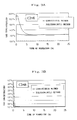
- Figure 4A shows the changes in the concentration of i-butane
- Fig. 4B shows the changes in the concentration of n-butane
- Fig. 4C shows the changes in the concentration of nitrogen.
- the initial concentration (I) is given by broken line
- the initial concentration (II) is given by solid line.
Landscapes
- Chemical & Material Sciences (AREA)
- Oil, Petroleum & Natural Gas (AREA)
- Organic Chemistry (AREA)
- Life Sciences & Earth Sciences (AREA)
- Environmental & Geological Engineering (AREA)
- General Life Sciences & Earth Sciences (AREA)
- Geochemistry & Mineralogy (AREA)
- Geology (AREA)
- Engineering & Computer Science (AREA)
- Chemical Kinetics & Catalysis (AREA)
- General Chemical & Material Sciences (AREA)
- Organic Low-Molecular-Weight Compounds And Preparation Thereof (AREA)
Applications Claiming Priority (2)
| Application Number | Priority Date | Filing Date | Title |
|---|---|---|---|
| JP2007093948A JP2008248190A (ja) | 2007-03-30 | 2007-03-30 | 混合ガスハイドレート製造方法 |
| PCT/JP2008/056243 WO2008120767A1 (ja) | 2007-03-30 | 2008-03-28 | 混合ガスハイドレート製造方法 |
Publications (2)
| Publication Number | Publication Date |
|---|---|
| EP2130896A1 true EP2130896A1 (de) | 2009-12-09 |
| EP2130896A4 EP2130896A4 (de) | 2012-10-31 |
Family
ID=39808347
Family Applications (1)
| Application Number | Title | Priority Date | Filing Date |
|---|---|---|---|
| EP08739361A Withdrawn EP2130896A4 (de) | 2007-03-30 | 2008-03-28 | Verfahren zur herstellung eines gemischten gashydrats |
Country Status (6)
| Country | Link |
|---|---|
| US (1) | US8138382B2 (de) |
| EP (1) | EP2130896A4 (de) |
| JP (1) | JP2008248190A (de) |
| BR (1) | BRPI0807284A2 (de) |
| MY (1) | MY157934A (de) |
| WO (1) | WO2008120767A1 (de) |
Cited By (1)
| Publication number | Priority date | Publication date | Assignee | Title |
|---|---|---|---|---|
| EP2218766A4 (de) * | 2007-10-03 | 2012-08-22 | Mitsui Shipbuilding Eng | Verfahren und vorrichtung zur herstellung von gashydratpellet |
Families Citing this family (7)
| Publication number | Priority date | Publication date | Assignee | Title |
|---|---|---|---|---|
| JP4917945B2 (ja) * | 2007-03-30 | 2012-04-18 | 三井造船株式会社 | ガスハイドレートの脱水装置 |
| JP5529504B2 (ja) * | 2009-11-13 | 2014-06-25 | 三井造船株式会社 | 混合ガスハイドレート製造プラントの運転方法 |
| US8354565B1 (en) * | 2010-06-14 | 2013-01-15 | U.S. Department Of Energy | Rapid gas hydrate formation process |
| KR101299718B1 (ko) * | 2011-09-19 | 2013-08-28 | 한국생산기술연구원 | 기체액체 순환형 하이드레이트 반응기 |
| JP2016087594A (ja) * | 2014-11-11 | 2016-05-23 | 三井造船株式会社 | ガスハイドレートの塊製造装置、塊製造方法、及びガスハイドレートの塊 |
| CN108505976B (zh) * | 2018-03-19 | 2020-12-11 | 西南石油大学 | 一种利用耦合冷冻墙降压开采海洋天然气水合物的方法 |
| CN110469769B (zh) * | 2018-05-12 | 2021-04-06 | 中国石油化工股份有限公司 | 一种利用lng冷能与压力能的天然气水合物生成系统 |
Family Cites Families (11)
| Publication number | Priority date | Publication date | Assignee | Title |
|---|---|---|---|---|
| NO172080C (no) * | 1990-01-29 | 1993-06-02 | Gudmundsson Jon Steinar | Framgangsmaate for framstilling av gasshydrater og apparattil utfoerelse av samme |
| US5536893A (en) * | 1994-01-07 | 1996-07-16 | Gudmundsson; Jon S. | Method for production of gas hydrates for transportation and storage |
| JP2002038171A (ja) * | 2000-07-19 | 2002-02-06 | Mitsubishi Heavy Ind Ltd | ハイドレートの製造方法および製造装置、天然ガスの貯蔵方法 |
| CA2410578A1 (en) * | 2001-03-29 | 2002-11-25 | Mitsubishi Heavy Industries, Ltd. | Gas hydrate production device and gas hydrate dehydrating device |
| JP2003064385A (ja) * | 2001-08-24 | 2003-03-05 | Mitsubishi Heavy Ind Ltd | ガスハイドレートの生成システムおよび生成方法 |
| JP4751025B2 (ja) * | 2004-01-22 | 2011-08-17 | 三井造船株式会社 | ガスハイドレートの製造装置 |
| JP2005320454A (ja) * | 2004-05-10 | 2005-11-17 | Mitsui Eng & Shipbuild Co Ltd | 天然ガスハイドレートの製造方法及び製造装置 |
| JP2006104256A (ja) * | 2004-10-01 | 2006-04-20 | Mitsui Eng & Shipbuild Co Ltd | ガスハイドレートペレットの製造方法 |
| WO2007002608A2 (en) * | 2005-06-27 | 2007-01-04 | Solid Gas Technologies Llc | Clathrate hydrate modular storage, applications and utilization processes |
| WO2007116456A1 (ja) * | 2006-03-30 | 2007-10-18 | Mitsui Engineering & Shipbuilding Co., Ltd. | ガスハイドレートペレットの製造方法 |
| EP2128228A4 (de) * | 2007-02-19 | 2010-10-13 | Mitsui Shipbuilding Eng | Verfahren zur herstellung, zur aufbewahrung und zum transport für gashydrat |
-
2007
- 2007-03-30 JP JP2007093948A patent/JP2008248190A/ja active Pending
-
2008
- 2008-03-28 MY MYPI20093291A patent/MY157934A/en unknown
- 2008-03-28 WO PCT/JP2008/056243 patent/WO2008120767A1/ja not_active Ceased
- 2008-03-28 EP EP08739361A patent/EP2130896A4/de not_active Withdrawn
- 2008-03-28 US US12/449,435 patent/US8138382B2/en not_active Expired - Fee Related
- 2008-03-28 BR BRPI0807284-1A2A patent/BRPI0807284A2/pt not_active IP Right Cessation
Cited By (1)
| Publication number | Priority date | Publication date | Assignee | Title |
|---|---|---|---|---|
| EP2218766A4 (de) * | 2007-10-03 | 2012-08-22 | Mitsui Shipbuilding Eng | Verfahren und vorrichtung zur herstellung von gashydratpellet |
Also Published As
| Publication number | Publication date |
|---|---|
| JP2008248190A (ja) | 2008-10-16 |
| US8138382B2 (en) | 2012-03-20 |
| US20110015455A1 (en) | 2011-01-20 |
| MY157934A (en) | 2016-08-15 |
| EP2130896A4 (de) | 2012-10-31 |
| WO2008120767A1 (ja) | 2008-10-09 |
| BRPI0807284A2 (pt) | 2014-10-21 |
Similar Documents
| Publication | Publication Date | Title |
|---|---|---|
| US8138382B2 (en) | Process for producing mixed gas hydrate | |
| CA2214373C (en) | A method of producing gas hydrate | |
| AU2002349639B2 (en) | Process for producing gas clathrate and production apparatus | |
| RU2509208C2 (ru) | Способ получения объединенного газообразного углеводородного потока и жидких углеводородных потоков и устройство для его осуществления | |
| PL210868B1 (pl) | Sposób odzyskiwania etylenu | |
| US20130237617A1 (en) | Process for producing a methane-containing gas from synthesis gas and methane production plant for carrying out the process | |
| CN111577213B (zh) | 一种海洋可燃冰开采气体固态化储运的系统与方法 | |
| US8921626B2 (en) | Method for operating plant for producing mixed-gas hydrate | |
| CN107399737B (zh) | 一种用于高压粉煤气化的高压气相二氧化碳的制备方法 | |
| EP3663381B1 (de) | Verfahren zur kühlung eines pyrolyseprodukts | |
| CN218494769U (zh) | 一种解析气与闪蒸气连通回收系统 | |
| CN103865599A (zh) | 液化天然气的制造方法 | |
| CN109593579B (zh) | 一种一次通过甲烷化工艺 | |
| US6508931B1 (en) | Process for the production of white oil | |
| DE102009015199A1 (de) | Verfahren zur Herstellung von Gashydraten | |
| CN1223511C (zh) | 一种生产亚硝酸钙的新工艺及其设备 | |
| CA2620734A1 (en) | Method of producing a hydrocarbon stream from a subterranean zone | |
| CN1272618A (zh) | 利用水合物分离提浓氢气的方法 | |
| CN120662227A (zh) | 一种低排放的顺序流程乙烯装置及其开车方法 | |
| CN116355655B (zh) | 一种加氢气化方法 | |
| RU2191170C2 (ru) | Способ производства жидких синтетических моторных топлив | |
| CN215655082U (zh) | 一种流化床反应器旋风分离器料腿吹扫装置 | |
| KR20240150864A (ko) | Psa 테일 가스를 이용하여 이산화탄소를 제거하는 장치 및 방법 | |
| WO2023009689A1 (en) | Methods and systems for natural gas purification integrated with gas compression | |
| JPH021197B2 (de) |
Legal Events
| Date | Code | Title | Description |
|---|---|---|---|
| PUAI | Public reference made under article 153(3) epc to a published international application that has entered the european phase |
Free format text: ORIGINAL CODE: 0009012 |
|
| 17P | Request for examination filed |
Effective date: 20090814 |
|
| AK | Designated contracting states |
Kind code of ref document: A1 Designated state(s): AT BE BG CH CY CZ DE DK EE ES FI FR GB GR HR HU IE IS IT LI LT LU LV MC MT NL NO PL PT RO SE SI SK TR |
|
| DAX | Request for extension of the european patent (deleted) | ||
| A4 | Supplementary search report drawn up and despatched |
Effective date: 20121002 |
|
| RIC1 | Information provided on ipc code assigned before grant |
Ipc: C10L 3/06 20060101AFI20120926BHEP Ipc: C10L 3/10 20060101ALI20120926BHEP Ipc: C07C 9/04 20060101ALI20120926BHEP Ipc: C07C 5/00 20060101ALI20120926BHEP Ipc: C07C 7/20 20060101ALI20120926BHEP |
|
| GRAP | Despatch of communication of intention to grant a patent |
Free format text: ORIGINAL CODE: EPIDOSNIGR1 |
|
| INTG | Intention to grant announced |
Effective date: 20140820 |
|
| RAP1 | Party data changed (applicant data changed or rights of an application transferred) |
Owner name: MITSUI ENGINEERING & SHIPBUILDING CO., LTD. |
|
| RIN1 | Information on inventor provided before grant (corrected) |
Inventor name: TAKAHASHI, MASAHIRO Inventor name: KANDA, NOBUYASU Inventor name: IWASAKI, TORU |
|
| STAA | Information on the status of an ep patent application or granted ep patent |
Free format text: STATUS: THE APPLICATION IS DEEMED TO BE WITHDRAWN |
|
| 18D | Application deemed to be withdrawn |
Effective date: 20141001 |