EP2131016A1 - Instrument de mesure d'impédance et procédé de mesure d'impédance pour un collecteur de fines particules - Google Patents
Instrument de mesure d'impédance et procédé de mesure d'impédance pour un collecteur de fines particules Download PDFInfo
- Publication number
- EP2131016A1 EP2131016A1 EP08739254A EP08739254A EP2131016A1 EP 2131016 A1 EP2131016 A1 EP 2131016A1 EP 08739254 A EP08739254 A EP 08739254A EP 08739254 A EP08739254 A EP 08739254A EP 2131016 A1 EP2131016 A1 EP 2131016A1
- Authority
- EP
- European Patent Office
- Prior art keywords
- fine particle
- particle collection
- ammeter
- power supply
- impedance
- Prior art date
- Legal status (The legal status is an assumption and is not a legal conclusion. Google has not performed a legal analysis and makes no representation as to the accuracy of the status listed.)
- Withdrawn
Links
Images


Classifications
-
- F—MECHANICAL ENGINEERING; LIGHTING; HEATING; WEAPONS; BLASTING
- F01—MACHINES OR ENGINES IN GENERAL; ENGINE PLANTS IN GENERAL; STEAM ENGINES
- F01N—GAS-FLOW SILENCERS OR EXHAUST APPARATUS FOR MACHINES OR ENGINES IN GENERAL; GAS-FLOW SILENCERS OR EXHAUST APPARATUS FOR INTERNAL-COMBUSTION ENGINES
- F01N9/00—Electrical control of exhaust gas treating apparatus
- F01N9/002—Electrical control of exhaust gas treating apparatus of filter regeneration
-
- G—PHYSICS
- G01—MEASURING; TESTING
- G01N—INVESTIGATING OR ANALYSING MATERIALS BY DETERMINING THEIR CHEMICAL OR PHYSICAL PROPERTIES
- G01N15/00—Investigating characteristics of particles; Investigating permeability, pore-volume or surface-area of porous materials
- G01N15/06—Investigating concentration of particle suspensions
- G01N15/0656—Investigating concentration of particle suspensions using electric, e.g. electrostatic methods or magnetic methods
-
- F—MECHANICAL ENGINEERING; LIGHTING; HEATING; WEAPONS; BLASTING
- F01—MACHINES OR ENGINES IN GENERAL; ENGINE PLANTS IN GENERAL; STEAM ENGINES
- F01N—GAS-FLOW SILENCERS OR EXHAUST APPARATUS FOR MACHINES OR ENGINES IN GENERAL; GAS-FLOW SILENCERS OR EXHAUST APPARATUS FOR INTERNAL-COMBUSTION ENGINES
- F01N2560/00—Exhaust systems with means for detecting or measuring exhaust gas components or characteristics
- F01N2560/05—Exhaust systems with means for detecting or measuring exhaust gas components or characteristics the means being a particulate sensor
-
- G—PHYSICS
- G01—MEASURING; TESTING
- G01N—INVESTIGATING OR ANALYSING MATERIALS BY DETERMINING THEIR CHEMICAL OR PHYSICAL PROPERTIES
- G01N27/00—Investigating or analysing materials by the use of electric, electrochemical, or magnetic means
- G01N27/02—Investigating or analysing materials by the use of electric, electrochemical, or magnetic means by investigating impedance
- G01N27/04—Investigating or analysing materials by the use of electric, electrochemical, or magnetic means by investigating impedance by investigating resistance
- G01N27/043—Investigating or analysing materials by the use of electric, electrochemical, or magnetic means by investigating impedance by investigating resistance of a granular material
-
- Y—GENERAL TAGGING OF NEW TECHNOLOGICAL DEVELOPMENTS; GENERAL TAGGING OF CROSS-SECTIONAL TECHNOLOGIES SPANNING OVER SEVERAL SECTIONS OF THE IPC; TECHNICAL SUBJECTS COVERED BY FORMER USPC CROSS-REFERENCE ART COLLECTIONS [XRACs] AND DIGESTS
- Y02—TECHNOLOGIES OR APPLICATIONS FOR MITIGATION OR ADAPTATION AGAINST CLIMATE CHANGE
- Y02T—CLIMATE CHANGE MITIGATION TECHNOLOGIES RELATED TO TRANSPORTATION
- Y02T10/00—Road transport of goods or passengers
- Y02T10/10—Internal combustion engine [ICE] based vehicles
- Y02T10/40—Engine management systems
Definitions
- the present invention relates to an impedance measuring instrument and an impedance measuring method. More particularly, it relates to an impedance measuring instrument which can be used for measuring the quantity of fine particles deposited in a fine particle collector with a high precision, and an impedance measuring method.
- filtering by a filter is typical means.
- the material/structure of the filter include a fiber layer, ceramic foam and metal foam.
- a wall flow type is well known. This type of filter has a honeycomb structure including a plurality of cells as through channels of a gas which are defined by porous partition walls, and the ends of cells in each of the end surfaces of the honeycomb structure are alternately plugged so as to have a checker board pattern.
- the can body 3 is usually conductive, and one of the electrodes 7 and the can body 3 function as capacitors between which the buffering body 4 is sandwiched. Furthermore, the present inventors have found that the can body 3 and the other electrode 7 also function as capacitors between which the buffering body 4 is sandwiched.
- Fig. 6 is a schematic perspective view showing this behavior.
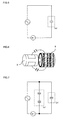
- Fig. 7 is an equivalent circuit diagram of an impedance measuring instrument of Fig. 6 . In Fig. 7 , a portion (x) surrounded with a dotted line shows the capacitor formed by the fine particle collection body and the electrode, and a portion (y) surrounded with a one-dot chain line shows the capacitor formed by the electrodes, the buffering body and the can body.
- Z y /Z x is sufficiently small, the following equation results.
- Z ⁇ 1 + ⁇ x / Z x • Z y / 1 + ⁇ x / Z x Z y
- an object of the present invention is to remove, from the above-mentioned impedance measuring instrument, the influences of the capacitors formed by the electrodes, the buffering body and the can body.
- an impedance measuring instrument and an impedance measuring method are provided as follows.
- An impedance measuring instrument of a fine particle collector comprising a fine particle collection body which collects fine particles in a fluid, a conductive can body which contains the fine particle collection body, and a buffering body disposed between the fine particle collection body and the conductive can body, wherein two or more electrodes are arranged on the fine particle collection body, at least one of the electrodes is connected with an AC power supply, at least the other electrode is connected with an ammeter, the AC power supply and the ammeter are interconnected and further connected with the conducive can body, and the conducive can body is grounded.
- An impedance measuring method of a fine particle collector comprising a fine particle collection body which collects fine particles in a fluid, a conductive can body which contains the fine particle collection body, and a buffering body disposed between the fine particle collection body and the conductive can body, the method comprising the steps of: arranging two or more electrodes on the fine particle collection body; connecting at least one of the electrodes with an AC power supply; connecting at least the other electrode with an ammeter; interconnecting the AC power supply and the ammeter, and further connecting the AC power supply and the ammeter with the conducive can body; grounding the conducive can body; supplying an alternate current of a constant frequency and a constant voltage from the AC power supply; measuring the current by the ammeter; and calculating an impedance from the voltage of the AC power supply and the current measured by the ammeter.
- a method of measuring a quantity of deposited particles on a fine particle collector comprising a fine particle collection body which collects fine particles in a fluid, a conductive can body which contains the fine particle collection body, and a buffering body disposed between the fine particle collection body and the conductive can body, the method comprising the steps of: arranging two or more electrodes on the fine particle collection body; connecting at least one of the electrodes with an AC power supply; connecting at least the other electrode with an ammeter; interconnecting the AC power supply and the ammeter, and further connecting the AC power supply and the ammeter with the conducive can body; grounding the conducive can body; supplying an alternate current of a constant frequency and a constant voltage from the AC power supply; measuring the current by the ammeter; calculating an impedance from the voltage of the AC power supply and the current measured by the ammeter; and calculating, from the calculated impedance, the quantity of the fine particles deposited on the fine particle collection body.
- the impedance measuring instrument of the present invention When the impedance measuring instrument of the present invention is used, the impedance of the fine particle collector can more accurately be measured. Therefore, the quantity of the fine particles deposited on the fine particle collector can more accurately be measured.
- 1 fine particle collector
- 2 fine particle collection body
- 3 can body
- 4 buffering body
- 5 end surface
- 6 side surface
- 7 electrode
- 8 AC power supply
- 9 ammeter
- 10 gas flow.
- Fig. 1 is a schematic diagram showing an impedance measuring instrument according to one embodiment of the present invention.
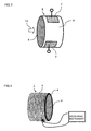
- Fig. 3 is a schematic perspective view of a fine particle collection body 2 which can be used for the impedance measuring instrument according to the embodiment of the present invention.
- the fine particle collection body 2 is provided with two electrodes 7 (see Fig. 3 ).
- One of the electrodes 7 is insulated from the can body 3, and a terminal of the electrode is exposed externally from the can body 3, and connected with an AC power supply 8. Moreover, the other electrode 7 is similarly insulated from the can body 3, and a terminal of the electrode is exposed externally from the can body 3, and connected with an ammeter 9. The AC power supply 8 and the ammeter 9 are interconnected, and further connected with the can body 3, and the can body 3 is further grounded. This behavior is shown in the equivalent circuit of Fig. 2 .
- the fine particle collection body is a main body which can collect a part or all of the fine particles in the fluid.
- the fine particle collection body usable in the present invention include a honeycomb structure and ceramic foam.
- the honeycomb structure is a structure having a large number of through channels (cells) defined by partition walls and extending in an axial direction.
- a fine particle collection filter is a filter having the honeycomb structure including a plurality of cells as the through channels of a gas which are defined by porous partition walls, and the ends of the cells in each of the end surfaces of the honeycomb structure are alternately plugged so as to form a checker board pattern.
- the honeycomb structure which is substantially not plugged is not limited to a honeycomb structure which is not plugged at all, and may be a honeycomb structure which is plugged as much as about 10%.
- a honeycomb structure may be used in the impedance measuring instrument for exclusive use.
- the structure can be used as the DPF having an impedance measuring function.
- a base material of the fine particle collection body excluding the electrodes
- the material include a ceramic material such as silicon carbide, cordierite, alumina titanate, sialon, mullite, silicon nitride, zirconium phosphate, zirconia, titania, alumina or silica, a combination of them, and a material including a sintered metal as a main component.
- Examples of the can body usable in the present invention can include a stainless steel can body, because the body has excellent strength and thermal resistance and is lightweight. Such a can body usually has a conductivity.
- Examples of the buffering body usable in the present invention include a fiber including a ceramic material of alumina, silica or the like as a main component, the fiber being used in the form of a mat.
- the materials of the fine particle collection body and the electrode are preferably selected, respectively, so that a difference between the thermal expansion coefficients of both of them is 20 ⁇ 10 -6 /°C or less.
- the impedance measuring instrument of the present invention when used right under an engine, the instrument is exposed to an environment at a high temperature during use. Therefore, when the difference between the thermal expansion coefficients of the fine particle collection body and the electrode is excessively large, the fine particle collection body might break down or the electrode might peel owing to the difference between both the thermal expansion coefficients.
- the difference between both the thermal expansion coefficients is 20 ⁇ 10 -6 /C or less, the possibility of the occurrence of such a defect lowers.
- the electrode may be a flat plate-like electrode or an electrode formed in a cylindrical shape.
- a ceramic material may be preferably formed into the electrode by a process such as tape forming, extrusion, pressing, injection or casting.
- examples of the main component of the ceramic material include silicon nitride, aluminum nitride, dense cordierite, and a composite material of oxide, nitride, carbide or boride.
- the main component of the ceramic material is preferably at least one compound selected from the group consisting of silicon nitride, aluminum nitride, dense cordierite, an aluminum oxide based composite material, a silicon carbide based composite material and a mullite based composite material.
- the silicon carbide based composite material to which boron nitride (BN) particles capable of increasing the electric resistance of silicon carbide having a high thermal conductivity are added is suitable for the electrode material which functions as a dielectric material.
- the mullite based composite material is suitable as the main component, in which for a purpose of increasing the thermal conductivity of mullite having a small thermal expansion coefficient but a low thermal conductivity, silicon carbide particles are dispersed. A difference between the thermal expansion coefficients of both the materials is small, and hence a residual stress generated in the materials is small. It is difficult to sinter both the materials, but a metal material has a simple flat plate-like shape, and hence pressurization firing can easily be applied. It is to be noted that in the present embodiment, the main component occupies 60 mass% or more of the components.
- a tape-like formed ceramic material (a green tape) is used as the ceramic material, and the tape-like formed ceramic material may be coated with the above electrode.
- a specific coating process include screen printing, calender roll, spray, electrostatic coating, dip, knife coater, chemical evaporation and physical evaporation. According to such a process, the coated surface of the material has an excellent smoothness, and it is possible to easily form a thin ceramic material in which the electrodes are embedded.
- the unfired ceramic material coated with the electrode and another unfired ceramic material are stacked so as to cover the electrode. Finally, the unfired and stacked ceramic materials are fired while the electrode is sandwiched between the materials, whereby the electrode embedded in the ceramic material is formed.
- the fine particle collection body and the ceramic material are preferably made of the same main component.
- the close attaching properties between the ceramic material with the electrode embedded therein and the fine particle collection body become satisfactory.
- the impedance measuring instrument of the present invention might be exposed at a high temperature during use, but there is theoretically not any difference between the thermal expansion coefficients of both the materials, and hence breakdown due to heat, the peeling of the electrode and the like can be alleviated.
- Both the fine particle collection body and the ceramic material may be made of cordierite as the main component.
- AC power supply used in the present invention.
- An AC power supply broadly used in the industry may be used.
- a voltage value but it is necessary to apply a voltage which is not more than such a voltage level that any dielectric breakdown is not caused, or a voltage in a range in which the current can be measured.
- the power supply is preferably used at 36 Vp-p or less at which an IC of an operating amplifier or the like can be used, and a voltage of 1 Vp-p or more is preferably applied so that the measurement current does not become excessively small.
- ammeter used in the present invention.
- An ammeter broadly used in the industry may be used.
- the quantity of the collected fine particles can be determined.
- an AC impedance between the electrodes can be measured to determine the quantity of the collected fine particles. That is, the AC impedance between the electrodes provided in the fine particle collection body can be measured to measure the change of capacitance between the electrodes due to the deposition of the fine particles in the fine particle collection body.
- the capacitance between the electrodes or the like changes in accordance with the absolute quantity of the fine particles in the fine particle collection body, and hence the quantity of the fine particles deposited in the fine particle collection body can uniquely be determined from the measured data of the AC impedance.
- a graph or the like indicating a relation between the mass of the deposited fine particles and the AC impedance is prepared based on actually measured values, whereby the AC impedance is measured to determine the quantity of the deposited fine particles during the measurement.
- the value of the inductance of the coil to be connected may be set so as to satisfy the resonance conditions with the targeted quantity of the deposited fine particles. That is, the value of the inductance is controlled by using a variable inductance or the like so that the AC impedance immediately comes close to 0 when the quantity of the deposited fine particles reaches a predetermined value. It is to be noted that in the present invention, in addition to such an inductance, the capacitance, DC resistance and the like are connected in series or in parallel in the impedance measurement circuit, whereby the resonance conditions can be regulated.
- the frequency of the alternate current during the measuring of the AC impedance is preferably 100 Hz to 10 MHz.
- the frequency is less than 100 Hz, the impedance value of the honeycomb structure remarkably increases. Therefore, a remarkably small current needs to be handled during the measuring of the impedance. Therefore, the measurement is easily influenced by noise, and the measurement precision of the fine particles lowers.
- the frequency exceeds 10 MHz, the influence of the inductance included in the whole measurement system including a lead wire which is used to pick up a signal from the honeycomb structure and the like cannot be ignored, and resonance with a capacity to be regulated is induced in the honeycomb structure and a wiring line.
- the frequency of the alternate current during the measuring of the AC impedance is preferably 1 kHz to 100 kHz.
- the powder of each of talc, kaolin, calcinated kaolin, alumina, aluminum hydroxide and silica was blended at a predetermined ratio so as to obtain chemical composition ranges of 42 to 56 mass% of SiO 2 , 0 to 45 mass% of Al 2 O 3 and 12 to 16 mass% of MgO, and 5 to 15 mass% in total of a synthetic resin such as PET, PMA or a phenol resin and 15 to 25 mass% of graphite as a pore former were added to the resultant cordierite forming material. Furthermore, predetermined amounts of methyl celluloses and a surfactant were further added, and water was added to this resultant mixture and kneaded to obtain a kneaded clay.
- this clay was vacuum-deaerated, and extruded into a honeycomb structure, followed by drying with microwaves and hot air and firing at a maximum temperature of 1400 to 1435°C.
- the honeycomb structure made of a porous ceramic material (cordierite) having a wall thickness of 0.05 mm, a cell density of 900 cpsi, a diameter of 106 mm and a length of 50 mm was manufactured.
- Two portions of the side surface of this honeycomb structure were coated with a silver paste having a rectangular shape of 25 mm ⁇ 151 mm so that the portions were just diagonally positioned, followed by firing, to form electrodes.
- an impedance measurement circuit was connected as shown in Fig. 8 .
- the honeycomb structure provided with the electrodes was received as a fine particle collection body in a can body.
- a diesel engine exhaust gas including fine particles (soot) was passed through this can body, and the AC impedance between the electrodes was measured while depositing the fine particles in the honeycomb structure provided with the electrodes.
- Engine conditions of a diesel engine having a displacement of 2 L were set to a rotation number and torque of 1500 rpm/60 Nm and an EGR valve open degree of 0%.
- exhaust gas conditions included 214°C, a flow rate of 1.3 Nm 3 /min, and a fine particle concentration of 6.3 mg/m 3 .
- the measurement results of impedances in an initial state and after an operation for three hours are shown in Table 1.
- Impedances in an initial state and after an operation for three hours were measured in the same manner as in the above example except that in the honeycomb structure prepared in the above example, an impedance measurement circuit was connected as shown in Fig. 4 . Results are shown in Table 1.
- the impedance measuring instrument of the present invention has a satisfactory sensitivity as compared with an impedance measuring instrument of the comparative example.
- the present invention can be used for measuring the quantity of discharged fine particles from an exhaust system of an internal combustion engine or the like.
Landscapes
- Chemical & Material Sciences (AREA)
- Engineering & Computer Science (AREA)
- Life Sciences & Earth Sciences (AREA)
- Analytical Chemistry (AREA)
- General Engineering & Computer Science (AREA)
- Dispersion Chemistry (AREA)
- Physics & Mathematics (AREA)
- Health & Medical Sciences (AREA)
- Combustion & Propulsion (AREA)
- Mechanical Engineering (AREA)
- Biochemistry (AREA)
- General Health & Medical Sciences (AREA)
- General Physics & Mathematics (AREA)
- Immunology (AREA)
- Pathology (AREA)
- Investigating Or Analyzing Materials By The Use Of Electric Means (AREA)
- Measurement Of Resistance Or Impedance (AREA)
- Filtering Of Dispersed Particles In Gases (AREA)
Applications Claiming Priority (2)
| Application Number | Priority Date | Filing Date | Title |
|---|---|---|---|
| JP2007083326 | 2007-03-28 | ||
| PCT/JP2008/056136 WO2008117869A1 (fr) | 2007-03-28 | 2008-03-28 | Instrument de mesure d'impédance et procédé de mesure d'impédance pour un collecteur de fines particules |
Publications (2)
| Publication Number | Publication Date |
|---|---|
| EP2131016A1 true EP2131016A1 (fr) | 2009-12-09 |
| EP2131016A4 EP2131016A4 (fr) | 2014-07-02 |
Family
ID=39788600
Family Applications (1)
| Application Number | Title | Priority Date | Filing Date |
|---|---|---|---|
| EP08739254.4A Withdrawn EP2131016A4 (fr) | 2007-03-28 | 2008-03-28 | Instrument de mesure d'impédance et procédé de mesure d'impédance pour un collecteur de fines particules |
Country Status (4)
| Country | Link |
|---|---|
| US (1) | US20090315569A1 (fr) |
| EP (1) | EP2131016A4 (fr) |
| JP (1) | JP5068311B2 (fr) |
| WO (1) | WO2008117869A1 (fr) |
Cited By (4)
| Publication number | Priority date | Publication date | Assignee | Title |
|---|---|---|---|---|
| US9062576B2 (en) | 2010-12-22 | 2015-06-23 | Caterpillar Inc. | Exhaust particulate filter system and operating method therefor |
| CN106770483A (zh) * | 2016-12-29 | 2017-05-31 | 兰州大学 | 测量装置 |
| EP2656901A4 (fr) * | 2010-12-24 | 2017-07-05 | NGK Insulators, Ltd. | Structure en nid d'abeilles |
| EP2656900A4 (fr) * | 2010-12-24 | 2017-07-05 | NGK Insulators, Ltd. | Structure en nid d'abeilles |
Families Citing this family (6)
| Publication number | Priority date | Publication date | Assignee | Title |
|---|---|---|---|---|
| JP5625265B2 (ja) * | 2009-06-12 | 2014-11-19 | いすゞ自動車株式会社 | Pmセンサ |
| US8421481B2 (en) * | 2009-10-20 | 2013-04-16 | Analog Devices, Inc. | Detection and mitigation of particle contaminants in MEMS devices |
| JP6947980B2 (ja) | 2017-12-21 | 2021-10-13 | 富士通株式会社 | 粒子状物質検出器及びフィルタ処理装置 |
| JP7058536B2 (ja) * | 2018-03-29 | 2022-04-22 | 日本碍子株式会社 | ハニカム構造体 |
| JP7279489B2 (ja) * | 2019-04-17 | 2023-05-23 | 中国電力株式会社 | 計測装置及びその計測方法 |
| JP7569347B2 (ja) * | 2022-03-23 | 2024-10-17 | 日本碍子株式会社 | 乾燥体の製造方法及び製造装置 |
Family Cites Families (12)
| Publication number | Priority date | Publication date | Assignee | Title |
|---|---|---|---|---|
| JPS6047937A (ja) | 1983-08-26 | 1985-03-15 | Mitsubishi Motors Corp | ディ−ゼルパティキュレ−ト捕集量測定装置 |
| US4901024A (en) * | 1986-05-28 | 1990-02-13 | Sumitomo Electric Industries Ltd. | Apparatus for analyzing and separating particles and a system using the same |
| JPH06288227A (ja) * | 1993-04-07 | 1994-10-11 | Mitsubishi Materials Corp | 排ガス浄化装置 |
| JP4260345B2 (ja) * | 2000-07-03 | 2009-04-30 | 日産ディーゼル工業株式会社 | ディーゼルエンジンの排気浄化装置 |
| CA2570314C (fr) * | 2003-06-17 | 2013-08-20 | Completion Products Pte. Ltd. | Ecran de puits |
| DE102004007041A1 (de) * | 2004-02-12 | 2005-09-01 | Daimlerchrysler Ag | Verfahren zum Betreiben eines Partikelfilters |
| DE502005003454D1 (de) * | 2004-02-12 | 2008-05-08 | Daimler Ag | Vorrichtung zur feststellung des zustands eines russpartikelfilters |
| DE102004007039A1 (de) | 2004-02-12 | 2005-09-01 | Daimlerchrysler Ag | Vorrichtung und Verfahren zur Ermittlung des Beladungszustands eines Partikelfilters |
| DE102004007634A1 (de) * | 2004-02-17 | 2005-09-08 | Siemens Ag | Verfahren und Vorrichtung zur Überwachung der Partikelkonzentration in einem Gasstrom |
| DE102005016395B4 (de) * | 2005-04-18 | 2012-08-23 | Andreas Hauser | Rußimpedanzsensor |
| JP2007090255A (ja) * | 2005-09-29 | 2007-04-12 | Toyota Motor Corp | 排ガス浄化装置 |
| WO2008096853A1 (fr) * | 2007-02-09 | 2008-08-14 | Ngk Insulators, Ltd. | Instrument servant à mesurer une concentration de particules dans un fluide, procédé de mesure, et programme de mesure |
-
2008
- 2008-03-28 WO PCT/JP2008/056136 patent/WO2008117869A1/fr not_active Ceased
- 2008-03-28 JP JP2009506385A patent/JP5068311B2/ja not_active Expired - Fee Related
- 2008-03-28 EP EP08739254.4A patent/EP2131016A4/fr not_active Withdrawn
-
2009
- 2009-08-27 US US12/548,737 patent/US20090315569A1/en not_active Abandoned
Cited By (5)
| Publication number | Priority date | Publication date | Assignee | Title |
|---|---|---|---|---|
| US9062576B2 (en) | 2010-12-22 | 2015-06-23 | Caterpillar Inc. | Exhaust particulate filter system and operating method therefor |
| EP2656901A4 (fr) * | 2010-12-24 | 2017-07-05 | NGK Insulators, Ltd. | Structure en nid d'abeilles |
| EP2656900A4 (fr) * | 2010-12-24 | 2017-07-05 | NGK Insulators, Ltd. | Structure en nid d'abeilles |
| CN106770483A (zh) * | 2016-12-29 | 2017-05-31 | 兰州大学 | 测量装置 |
| CN106770483B (zh) * | 2016-12-29 | 2023-10-20 | 兰州大学 | 测量装置 |
Also Published As
| Publication number | Publication date |
|---|---|
| JPWO2008117869A1 (ja) | 2010-07-15 |
| EP2131016A4 (fr) | 2014-07-02 |
| JP5068311B2 (ja) | 2012-11-07 |
| US20090315569A1 (en) | 2009-12-24 |
| WO2008117869A1 (fr) | 2008-10-02 |
Similar Documents
| Publication | Publication Date | Title |
|---|---|---|
| EP2131016A1 (fr) | Instrument de mesure d'impédance et procédé de mesure d'impédance pour un collecteur de fines particules | |
| US20080229931A1 (en) | Honeycomb structure body and method for producing the same | |
| US7977955B2 (en) | Particulate matter sensor | |
| US8305087B2 (en) | Particulate matter detection device | |
| JP2008064621A (ja) | 微粒子センサ | |
| KR20090125114A (ko) | 입자상 물질 검출 장치 및 입자상 물질 검출 방법 | |
| JP4512658B2 (ja) | 粒子状物質検出装置 | |
| JP2766029B2 (ja) | セラミックグリーンシート材及び電気化学的素子並びにその製造方法 | |
| JP5010494B2 (ja) | 粒子状物質検出装置 | |
| JP5010530B2 (ja) | 粒子状物質検出装置 | |
| JP5219710B2 (ja) | 粒子状物質検出装置及びその製造方法 | |
| EP1964655A1 (fr) | Procédé de fabrication d'un élément structuré en nid d'abeille | |
| JP2008223495A (ja) | 温度測定ハニカム構造体 | |
| KR20100014456A (ko) | 입자상 물질 검출 장치 | |
| US20120006094A1 (en) | Particulate matter detector, and method for detecting particulate matter | |
| JP2008231930A (ja) | ハニカム構造体の微粒子堆積量測定方法 | |
| CN101321934A (zh) | 蜂窝结构体及其制造方法 | |
| JP2008008151A (ja) | 微粒子センサ用ハニカム構造体 | |
| JP4855811B2 (ja) | 微粒子量検出システム | |
| EP3767285A1 (fr) | Capteur de composé | |
| JP2008063985A (ja) | 微粒子センサ用ハニカム構造体 | |
| JP2011247725A (ja) | センサ素子 | |
| JP2008018388A (ja) | 電極付ハニカム構造体 | |
| CN112730177B (zh) | 一种颗粒物传感器及其制造方法 | |
| JP2008240631A (ja) | ハニカム構造体および微粒子付着量測定方法 |
Legal Events
| Date | Code | Title | Description |
|---|---|---|---|
| PUAI | Public reference made under article 153(3) epc to a published international application that has entered the european phase |
Free format text: ORIGINAL CODE: 0009012 |
|
| 17P | Request for examination filed |
Effective date: 20090924 |
|
| AK | Designated contracting states |
Kind code of ref document: A1 Designated state(s): AT BE BG CH CY CZ DE DK EE ES FI FR GB GR HR HU IE IS IT LI LT LU LV MC MT NL NO PL PT RO SE SI SK TR |
|
| DAX | Request for extension of the european patent (deleted) | ||
| A4 | Supplementary search report drawn up and despatched |
Effective date: 20140603 |
|
| RIC1 | Information provided on ipc code assigned before grant |
Ipc: G01R 27/02 20060101ALI20140527BHEP Ipc: F01N 9/00 20060101ALI20140527BHEP Ipc: G01N 15/06 20060101ALI20140527BHEP Ipc: F01N 3/02 20060101AFI20140527BHEP Ipc: G01N 27/04 20060101ALI20140527BHEP |
|
| STAA | Information on the status of an ep patent application or granted ep patent |
Free format text: STATUS: THE APPLICATION HAS BEEN WITHDRAWN |
|
| 18W | Application withdrawn |
Effective date: 20140819 |