EP2131017B1 - Dispositif de nettoyage de gaz d'échappement - Google Patents
Dispositif de nettoyage de gaz d'échappement Download PDFInfo
- Publication number
- EP2131017B1 EP2131017B1 EP08739729.5A EP08739729A EP2131017B1 EP 2131017 B1 EP2131017 B1 EP 2131017B1 EP 08739729 A EP08739729 A EP 08739729A EP 2131017 B1 EP2131017 B1 EP 2131017B1
- Authority
- EP
- European Patent Office
- Prior art keywords
- electrode
- exhaust gas
- outer circumferential
- hollow cylindrical
- gas purifying
- Prior art date
- Legal status (The legal status is an assumption and is not a legal conclusion. Google has not performed a legal analysis and makes no representation as to the accuracy of the status listed.)
- Not-in-force
Links
Images


Classifications
-
- B—PERFORMING OPERATIONS; TRANSPORTING
- B03—SEPARATION OF SOLID MATERIALS USING LIQUIDS OR USING PNEUMATIC TABLES OR JIGS; MAGNETIC OR ELECTROSTATIC SEPARATION OF SOLID MATERIALS FROM SOLID MATERIALS OR FLUIDS; SEPARATION BY HIGH-VOLTAGE ELECTRIC FIELDS
- B03C—MAGNETIC OR ELECTROSTATIC SEPARATION OF SOLID MATERIALS FROM SOLID MATERIALS OR FLUIDS; SEPARATION BY HIGH-VOLTAGE ELECTRIC FIELDS
- B03C3/00—Separating dispersed particles from gases or vapour, e.g. air, by electrostatic effect
- B03C3/34—Constructional details or accessories or operation thereof
- B03C3/40—Electrode constructions
- B03C3/41—Ionising-electrodes
-
- B—PERFORMING OPERATIONS; TRANSPORTING
- B03—SEPARATION OF SOLID MATERIALS USING LIQUIDS OR USING PNEUMATIC TABLES OR JIGS; MAGNETIC OR ELECTROSTATIC SEPARATION OF SOLID MATERIALS FROM SOLID MATERIALS OR FLUIDS; SEPARATION BY HIGH-VOLTAGE ELECTRIC FIELDS
- B03C—MAGNETIC OR ELECTROSTATIC SEPARATION OF SOLID MATERIALS FROM SOLID MATERIALS OR FLUIDS; SEPARATION BY HIGH-VOLTAGE ELECTRIC FIELDS
- B03C3/00—Separating dispersed particles from gases or vapour, e.g. air, by electrostatic effect
- B03C3/02—Plant or installations having external electricity supply
- B03C3/04—Plant or installations having external electricity supply dry type
- B03C3/12—Plant or installations having external electricity supply dry type characterised by separation of ionising and collecting stations
-
- B—PERFORMING OPERATIONS; TRANSPORTING
- B03—SEPARATION OF SOLID MATERIALS USING LIQUIDS OR USING PNEUMATIC TABLES OR JIGS; MAGNETIC OR ELECTROSTATIC SEPARATION OF SOLID MATERIALS FROM SOLID MATERIALS OR FLUIDS; SEPARATION BY HIGH-VOLTAGE ELECTRIC FIELDS
- B03C—MAGNETIC OR ELECTROSTATIC SEPARATION OF SOLID MATERIALS FROM SOLID MATERIALS OR FLUIDS; SEPARATION BY HIGH-VOLTAGE ELECTRIC FIELDS
- B03C3/00—Separating dispersed particles from gases or vapour, e.g. air, by electrostatic effect
- B03C3/34—Constructional details or accessories or operation thereof
- B03C3/40—Electrode constructions
- B03C3/45—Collecting-electrodes
- B03C3/49—Collecting-electrodes tubular
-
- B—PERFORMING OPERATIONS; TRANSPORTING
- B03—SEPARATION OF SOLID MATERIALS USING LIQUIDS OR USING PNEUMATIC TABLES OR JIGS; MAGNETIC OR ELECTROSTATIC SEPARATION OF SOLID MATERIALS FROM SOLID MATERIALS OR FLUIDS; SEPARATION BY HIGH-VOLTAGE ELECTRIC FIELDS
- B03C—MAGNETIC OR ELECTROSTATIC SEPARATION OF SOLID MATERIALS FROM SOLID MATERIALS OR FLUIDS; SEPARATION BY HIGH-VOLTAGE ELECTRIC FIELDS
- B03C3/00—Separating dispersed particles from gases or vapour, e.g. air, by electrostatic effect
- B03C3/34—Constructional details or accessories or operation thereof
- B03C3/40—Electrode constructions
- B03C3/45—Collecting-electrodes
- B03C3/51—Catch- space electrodes, e.g. slotted-box form
-
- B—PERFORMING OPERATIONS; TRANSPORTING
- B03—SEPARATION OF SOLID MATERIALS USING LIQUIDS OR USING PNEUMATIC TABLES OR JIGS; MAGNETIC OR ELECTROSTATIC SEPARATION OF SOLID MATERIALS FROM SOLID MATERIALS OR FLUIDS; SEPARATION BY HIGH-VOLTAGE ELECTRIC FIELDS
- B03C—MAGNETIC OR ELECTROSTATIC SEPARATION OF SOLID MATERIALS FROM SOLID MATERIALS OR FLUIDS; SEPARATION BY HIGH-VOLTAGE ELECTRIC FIELDS
- B03C3/00—Separating dispersed particles from gases or vapour, e.g. air, by electrostatic effect
- B03C3/34—Constructional details or accessories or operation thereof
- B03C3/74—Cleaning the electrodes
-
- F—MECHANICAL ENGINEERING; LIGHTING; HEATING; WEAPONS; BLASTING
- F01—MACHINES OR ENGINES IN GENERAL; ENGINE PLANTS IN GENERAL; STEAM ENGINES
- F01N—GAS-FLOW SILENCERS OR EXHAUST APPARATUS FOR MACHINES OR ENGINES IN GENERAL; GAS-FLOW SILENCERS OR EXHAUST APPARATUS FOR INTERNAL-COMBUSTION ENGINES
- F01N3/00—Exhaust or silencing apparatus having means for purifying, rendering innocuous, or otherwise treating exhaust
- F01N3/01—Exhaust or silencing apparatus having means for purifying, rendering innocuous, or otherwise treating exhaust by means of electric or electrostatic separators
-
- B—PERFORMING OPERATIONS; TRANSPORTING
- B03—SEPARATION OF SOLID MATERIALS USING LIQUIDS OR USING PNEUMATIC TABLES OR JIGS; MAGNETIC OR ELECTROSTATIC SEPARATION OF SOLID MATERIALS FROM SOLID MATERIALS OR FLUIDS; SEPARATION BY HIGH-VOLTAGE ELECTRIC FIELDS
- B03C—MAGNETIC OR ELECTROSTATIC SEPARATION OF SOLID MATERIALS FROM SOLID MATERIALS OR FLUIDS; SEPARATION BY HIGH-VOLTAGE ELECTRIC FIELDS
- B03C2201/00—Details of magnetic or electrostatic separation
- B03C2201/08—Ionising electrode being a rod
-
- B—PERFORMING OPERATIONS; TRANSPORTING
- B03—SEPARATION OF SOLID MATERIALS USING LIQUIDS OR USING PNEUMATIC TABLES OR JIGS; MAGNETIC OR ELECTROSTATIC SEPARATION OF SOLID MATERIALS FROM SOLID MATERIALS OR FLUIDS; SEPARATION BY HIGH-VOLTAGE ELECTRIC FIELDS
- B03C—MAGNETIC OR ELECTROSTATIC SEPARATION OF SOLID MATERIALS FROM SOLID MATERIALS OR FLUIDS; SEPARATION BY HIGH-VOLTAGE ELECTRIC FIELDS
- B03C2201/00—Details of magnetic or electrostatic separation
- B03C2201/10—Ionising electrode with two or more serrated ends or sides
-
- B—PERFORMING OPERATIONS; TRANSPORTING
- B03—SEPARATION OF SOLID MATERIALS USING LIQUIDS OR USING PNEUMATIC TABLES OR JIGS; MAGNETIC OR ELECTROSTATIC SEPARATION OF SOLID MATERIALS FROM SOLID MATERIALS OR FLUIDS; SEPARATION BY HIGH-VOLTAGE ELECTRIC FIELDS
- B03C—MAGNETIC OR ELECTROSTATIC SEPARATION OF SOLID MATERIALS FROM SOLID MATERIALS OR FLUIDS; SEPARATION BY HIGH-VOLTAGE ELECTRIC FIELDS
- B03C2201/00—Details of magnetic or electrostatic separation
- B03C2201/30—Details of magnetic or electrostatic separation for use in or with vehicles
-
- F—MECHANICAL ENGINEERING; LIGHTING; HEATING; WEAPONS; BLASTING
- F01—MACHINES OR ENGINES IN GENERAL; ENGINE PLANTS IN GENERAL; STEAM ENGINES
- F01N—GAS-FLOW SILENCERS OR EXHAUST APPARATUS FOR MACHINES OR ENGINES IN GENERAL; GAS-FLOW SILENCERS OR EXHAUST APPARATUS FOR INTERNAL-COMBUSTION ENGINES
- F01N2470/00—Structure or shape of exhaust gas passages, pipes or tubes
-
- Y—GENERAL TAGGING OF NEW TECHNOLOGICAL DEVELOPMENTS; GENERAL TAGGING OF CROSS-SECTIONAL TECHNOLOGIES SPANNING OVER SEVERAL SECTIONS OF THE IPC; TECHNICAL SUBJECTS COVERED BY FORMER USPC CROSS-REFERENCE ART COLLECTIONS [XRACs] AND DIGESTS
- Y02—TECHNOLOGIES OR APPLICATIONS FOR MITIGATION OR ADAPTATION AGAINST CLIMATE CHANGE
- Y02T—CLIMATE CHANGE MITIGATION TECHNOLOGIES RELATED TO TRANSPORTATION
- Y02T10/00—Road transport of goods or passengers
- Y02T10/10—Internal combustion engine [ICE] based vehicles
- Y02T10/12—Improving ICE efficiencies
-
- Y—GENERAL TAGGING OF NEW TECHNOLOGICAL DEVELOPMENTS; GENERAL TAGGING OF CROSS-SECTIONAL TECHNOLOGIES SPANNING OVER SEVERAL SECTIONS OF THE IPC; TECHNICAL SUBJECTS COVERED BY FORMER USPC CROSS-REFERENCE ART COLLECTIONS [XRACs] AND DIGESTS
- Y10—TECHNICAL SUBJECTS COVERED BY FORMER USPC
- Y10S—TECHNICAL SUBJECTS COVERED BY FORMER USPC CROSS-REFERENCE ART COLLECTIONS [XRACs] AND DIGESTS
- Y10S55/00—Gas separation
- Y10S55/38—Tubular collector electrode
Definitions
- the present invention relates to an exhaust gas purifying device capable of burning and removing particulate matter (hereinafter referred to as PM) in an exhaust gas from internal combustion engines, etc., with a direct current source.
- PM particulate matter
- Various harmful components are included in an exhaust gas discharged from an internal combustion engine used for automobiles, etc., or an incineration system.
- the harmful components it is particularly desirable to reduce NO x , SO x and PM emissions.
- Diesel engines it has become desirable to reduce PM, and a particulate filter has been used to remove PM.
- Such a particulate filter has a porous honeycomb structure made of ceramics such as cordierite, etc. Inlet openings of passages compartmentalized in a grid form are alternately plugged, while the remaining passages whose inlet openings are not plugged are plugged at their outlet openings. Consequently, the exhaust gas passing through porous walls which define the passages can be discharged toward the downstream side. PM is captured on the inner surfaces of the porous walls because PM in the exhaust gas cannot pass through the porous walls.
- an exhaust gas purifying device (plasma reactor) has been recently proposed in which plasma is generated by a discharge, PM is burnt and removed by the oxidation action of the plasma, and NOx or the like is cleaned by the oxidation action of the plasma and the reduction action of a catalyst.
- Japanese Unexamined Patent Publication (Kokai) No. 2001-162134 proposes an exhaust gas purifying system which comprises a circular cylindrical outer circumference electrode, a discharge metal wire electrode at the center part of the outer circumference electrode, and an electrically insulated hollow cylindrical body inside the outer circumference electrode.
- the outer circumference electrode is grounded
- the metal wire electrode is connected to a power supply source
- a discharge is generated between the outer circumference electrode and the metal wire electrode by the action of the power supply source to generate plasma
- an electrically insulated hollow cylindrical body is arranged between the outer circumference electrode and the metal wire electrode to avoid useless energy consumption of sparks.
- An object of the present invention is to provide an exhaust gas purifying device having an improved PM capture rate, etc., as well as energy efficiency to solve the problems.
- US 4 852 349 against which claim 1 is delimited, discloses an arrangement for the removal of soot particles from the exhaust gas stream of a diesel internal combustion engine. The soot particles are caught between conductor elements disposed at different potentials, produce a short circuit and are thereby burnt off.
- an exhaust gas purifying device comprising an electrically insulated hollow cylindrical case, a cylindrical outer circumferential electrode arranged on an inner wall of the hollow cylindrical case, a bar- shaped center electrode held on a center axis of the outer circumferential electrode, and a metallic hollow cylindrical body arranged between the outer circumferential electrode and the center electrode, wherein the metallic hollow cylindrical body is electrically insulated and has a plurality of holes to permit particulate matter to pass therethrough without being accumulated.
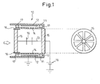
- the exhaust gas purifying device 10 comprises an electrically insulated hollow cylindrical case 11, a cylindrical outer circumferential electrode 12 arranged on an inner wall of the hollow cylindrical case, a bar-shaped center electrode 13 held on a center axis of the outer circumferential electrode, and a metallic hollow cylindrical body 14 arranged between the outer circumferential electrode and the center electrode.
- the center electrode 13 is held on a center axis of the outer circumferential electrode by a supporting material 15 made of an insulating material such as ceramics, etc.
- the center electrode 13 is connected to a power supply source 18, and the outer circumferential electrode 12 is grounded.
- the center electrode may be grounded and the outer circumferential electrode may be connected to the power supply source 18.
- the metallic hollow cylindrical body 14 is insulatedly fixed between the outer circumferential electrode and the center electrode by an insulation pipe 16 and an insulating fixing jig 17.
- the hollow cylindrical case 11, which holds the outer circumferential electrode 12 and defines an exhaust gas passage, may be made of any electrically insulating material including, but not limited to, ceramics or the like such as cordierite, alumina, etc.
- a cross-sectional shape thereof, which is not specifically limited, may be any shape and is preferably circular cylindrical.
- the center electrode 13 is made of such a material that electricity can be supplied between the center electrode 13 and the outer circumferential electrode 12.
- electrically conductive materials, semiconductive materials, etc. may be used.
- metallic materials are preferred.
- metallic materials specifically, copper, tungsten, stainless steel, iron, aluminum, etc., may be used. Above all, stainless steel is preferred in terms of cost and durability.
- wire is generally used but a hollow electrode can be used.
- the center electrode 13 is preferably provided with discharge projections 19.
- the discharge projections 19 are comprised of a plurality of thorny needles so that the ends thereof extend radially from the center electrode 13 towards the outer circumference electrode 12. The optimal number of the needle-like projections, which makes it possible to charge PM in the influent exhaust gas most effectively, can be experimentally determined.
- the outer circumferential electrode 12 is formed by arranging the same material as the center electrode 13 in a metallic mesh or metallic foil form on an inner wall of the hollow cylindrical case 11. Alternatively, the outer circumferential electrode 12 is formed by coating an electrically conductive paste onto an inner wall of the hollow cylindrical case 11.
- the outer circumferential electrode 12 may be of cylindrical shape centered on the center electrode 13, although it is preferably of circular cylindrical shape so that the entire surface is equidistant from the center electrode 13.
- the metallic hollow cylindrical body 14 arranged between the outer circumferential electrode 12 and the center electrode 13 is formed in a cylindrical shape using the same material as the outer circumferential electrode or the center electrode, and has a plurality of holes to permit PM in an influent exhaust gas to pass therethrough without being accumulated on the metallic hollow cylindrical body 14 for the purpose of an efficient discharge without an abnormal electrical discharge.
- a general size of PM is approximately 2.5 ⁇ m
- the size of the holes is sufficiently more than 2.5 ⁇ m.
- a general mesh cylindrical body may be used.
- the shape of the metallic hollow cylindrical body 14 may be of the same cylindrical shape as the outer circumferential electrode 12, although, for efficient discharge, it is preferably of circular cylindrical shape coaxial with the outer circumferential electrode 12 to prevent an abnormal discharge.
- the distance between the outer circumference electrode 12 and the metallic hollow cylindrical body 14 is set to be shorter than the distance between the metallic hollow cylindrical body 14 and the center electrode 13.
- An exhaust gas purifying device 10 comprising the components explained above is enclosed in a case, if necessary, and is connected to an exhaust pipe constituting an exhaust system of, for example, an internal combustion engine.
- An exhaust gas containing PM flows from the left side to the right side as indicated by the arrow in the drawing.
- PM is attracted to the outer circumference electrode 12, without being attracted to the insulated metallic hollow cylindrical body 14, to accumulate on the outer circumference electrode 12 through holes of the metallic hollow cylindrical body 14.
- the outer circumference electrode 12, the metallic hollow cylindrical body 14, and the center electrode 13 constitute a capacitor in terms of electricity because the metallic hollow cylindrical body 14 is insulated from the outer circumference electrode 12 and the center electrode 13 by an insulation pipe 16 and an insulating fixing jig 17. Electric charge is stored over time in the metallic hollow cylindrical body 14 through the center electrode 13 from the power supply source 18 to generate a discharge towards PM accumulated on the outer circumference electrode 12.
- the exhaust gas purifying device since electric charge is once stored in the metallic hollow cylindrical body 14 and thereafter discharged, it is possible to subject PM to an oxidation treatment using a direct current source without the need of generating a pulse discharge required to generate plasma or of a large amount of energy, unlike conventional exhaust gas purifying devices using plasma reactors.
- a PM charging unit on the upstream side of the exhaust gas flow in the exhaust gas purifying device 10.
- a configuration of a conventional exhaust gas purifying plasma reactor shown in FIG. 6 may be employed.
- One example of the exhaust gas purifying device according to the present invention comprising such a charging unit is shown in FIG. 2 .
- the unit 10 has the same configuration as the exhaust gas purifying device shown in FIG. 1 .
- the charging unit 20 arranged on the upstream side of the exhaust gas flow consists of the cylindrical outer circumference electrode 21 and the bar-shaped center electrode 22 held on a center axis of the outer circumference electrode 21.
- the outer circumference electrode 21 and the center electrode 22 can be made of the same material as the outer circumference electrode 12 and the center electrode 13. Further, the center electrode 22 is held on the center axis of the outer circumference 21 by the supporting member 15, and preferably further comprises discharge projections 23.
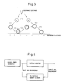
- the PM capture rate was measured using the configuration shown in FIG. 4 . Specifically, the operating condition of the diesel generator was at a rated power of 5 kW and at a gas flow rate of 820 mL/min, a digital dust meter was used as a PM particle number counter, and firstly the PM particle number of an inlet gas was measured. Then, the reactor 1 shown in FIG. 6 (This was the same configuration as unit 20 in FIG. 2 : the outer circumference electrode diameter: 80 mm, length: 380 mm, the number of discharge projections: 20) was installed as a collection reactor, and, 30 minutes after the installation, the PM particle number of an outlet gas was measured (Comparative example 1).
- the reactor 1 was removed, and the reactor 2 consisting of unit 10 (the outer circumference electrode diameter: 100 mm, length: 80 mm, the distance between the outer circumference electrode and the metallic hollow cylindrical body: 8 mm) and unit 20 was installed as a collection reactor. Electricity was not supplied by the power supply source 18, but was supplied by the power supply source 24 (-22 kV) alone, and, after 30 minutes, the PM particle number was measured (Comparative example 2). Then, the reactor 2 was removed, and the other reactor 2 consisting of unit 10 and unit 20 was installed, and voltages were applied by both power supply source 18 (-26 kV) and power supply source 24 (-22 kV), and then, after 30 minutes the PM particle number of an outlet gas was measured. The results are shown in Table 1. Table 1 Capture rate % Comparative example 1 90 Comparative example 2 90 Example 1 95
- the reactors in the example and the comparative examples have the same entire length of 380 mm.
- the unit 10 was installed to supply electricity from a power supply source, resulting in the increase of the PM capture rate.
- the PM oxidation rate was measured using the configuration shown in FIG. 5 . Specifically, a gas was flowed for one hour at a composition of O 2 10 L/min and N 2 40 L/min from a model gas generator through the collection reactor (the reactor temperature was 25 °C) having PM deposited thereon, used to capture PM in the above-mentioned PM capture rate measurement test, and the CO and CO 2 generated by the oxidation of PM were measured by a CO and CO 2 meter, and consequently, using the integrated values thereof, the PM oxidation rate was calculated.
- the present invention by arranging a metallic hollow cylindrical body electrically isolated between an outer circumference electrode and a center electrode, an electric charge from the center electrode is stored in the metallic hollow cylindrical body, and by discharging the electric charge to the outer circumference electrode, thereby PM can be oxidatively treated without using a pulse source which requires a large amount of energy, resulting in the reduction of necessary energy to a low level.
Landscapes
- Engineering & Computer Science (AREA)
- Chemical & Material Sciences (AREA)
- Combustion & Propulsion (AREA)
- Mechanical Engineering (AREA)
- General Engineering & Computer Science (AREA)
- Processes For Solid Components From Exhaust (AREA)
- Electrostatic Separation (AREA)
- Physical Or Chemical Processes And Apparatus (AREA)
Claims (6)
- Dispositif (10) de purification de gaz d'échappement comprenant une enveloppe cylindrique creuse isolée électriquement (11), une électrode circonférentielle externe cylindrique (12) disposée sur une paroi interne de l'enveloppe cylindrique creuse, une électrode centrale en forme de barre (13) maintenue sur l'axe central de l'électrode circonférentielle externe, et un corps cylindrique métallique creux (14) disposé entre l'électrode circonférentielle externe (12) et l'électrode centrale (13), dans lequel le corps cylindrique métallique creux (14) possède une pluralité de trous pour permettre à de la matière particulaire de passer à travers sans s'accumuler, caractérisé en ce que le corps cylindrique métallique creux est isolé électriquement (16, 17).
- Dispositif de purification de gaz d'échappement selon la revendication 1, dans lequel l'électrode centrale est raccordée à une source (18) de courant continu et l'électrode circonférentielle externe est mise à la masse.
- Dispositif de purification de gaz d'échappement selon la revendication 1, dans lequel l'électrode centrale est mise à la masse et l'électrode circonférentielle externe est raccordée à une source de courant continu.
- Dispositif de purification de gaz d'échappement selon l'une quelconque des revendications 1 à 3, dans lequel l'électrode centrale possède une pluralité de protubérances de décharge (19) dont les extrémités s'étendent radialement vers l'électrode circonférentielle externe.
- Dispositif de purification de gaz d'échappement selon la revendication 1, comprenant en outre une unité (20) de charge de particules située du côté amont de l'écoulement de gaz d'échappement.
- Dispositif de purification de gaz d'échappement selon la revendication 5, dans lequel l'unité de charge de particules comprend une électrode circonférentielle externe cylindrique (21) et une électrode centrale en forme de barre (22) maintenue sur l'axe central de l'électrode circonférentielle externe.
Applications Claiming Priority (2)
| Application Number | Priority Date | Filing Date | Title |
|---|---|---|---|
| JP2007088632A JP4873564B2 (ja) | 2007-03-29 | 2007-03-29 | 排ガス浄化装置 |
| PCT/JP2008/056619 WO2008123557A1 (fr) | 2007-03-29 | 2008-03-27 | Dispositif de nettoyage de gaz d'échappement |
Publications (3)
| Publication Number | Publication Date |
|---|---|
| EP2131017A1 EP2131017A1 (fr) | 2009-12-09 |
| EP2131017A4 EP2131017A4 (fr) | 2013-09-04 |
| EP2131017B1 true EP2131017B1 (fr) | 2014-10-29 |
Family
ID=39831029
Family Applications (1)
| Application Number | Title | Priority Date | Filing Date |
|---|---|---|---|
| EP08739729.5A Not-in-force EP2131017B1 (fr) | 2007-03-29 | 2008-03-27 | Dispositif de nettoyage de gaz d'échappement |
Country Status (5)
| Country | Link |
|---|---|
| US (1) | US8236094B2 (fr) |
| EP (1) | EP2131017B1 (fr) |
| JP (1) | JP4873564B2 (fr) |
| CN (1) | CN101636563B (fr) |
| WO (1) | WO2008123557A1 (fr) |
Families Citing this family (14)
| Publication number | Priority date | Publication date | Assignee | Title |
|---|---|---|---|---|
| JP6028348B2 (ja) * | 2012-03-14 | 2016-11-16 | 富士電機株式会社 | 電気集塵装置 |
| JP6172714B2 (ja) * | 2013-05-09 | 2017-08-02 | 臼井国際産業株式会社 | 重油を使用する船舶用ディーゼルエンジンの排ガス処理装置 |
| NL2011012C2 (en) * | 2013-06-19 | 2014-12-22 | Virus Free Air B V | Gas flow cleaning device. |
| CN104219863A (zh) * | 2014-09-23 | 2014-12-17 | 江苏大学 | 一种双介质低温等离子体发生器 |
| FR3039435B1 (fr) | 2015-07-28 | 2017-08-18 | Commissariat Energie Atomique | Methode et dispositif de collecte de particules d'aerosols, a collecte selective en fonction de la granulometrie des particules |
| FR3039433B1 (fr) * | 2015-07-28 | 2017-08-18 | Commissariat Energie Atomique | Methode d'epuration selective d'aerosols |
| KR102074398B1 (ko) * | 2016-06-15 | 2020-02-06 | 후지 덴키 가부시키가이샤 | 입자상 물질 연소장치 |
| CN109745817B (zh) * | 2019-02-28 | 2024-09-10 | 福建远致环保科技有限公司 | 一种电袋复合除尘装置 |
| CN109854342B (zh) * | 2019-04-15 | 2023-11-21 | 中国人民解放军战略支援部队航天工程大学 | 基于介质阻挡放电的一体化汽车尾气净化装置 |
| WO2020216367A1 (fr) * | 2019-04-25 | 2020-10-29 | 上海必修福企业管理有限公司 | Appareil et procédé de traitement de gaz cov |
| EP3950140A4 (fr) * | 2019-11-05 | 2022-06-29 | Fuji Electric Co., Ltd. | Précipitateur électrostatique |
| JP2022035345A (ja) * | 2020-08-20 | 2022-03-04 | 富士電機株式会社 | 電気集塵機 |
| NL2038554B1 (en) * | 2024-09-02 | 2026-03-17 | Vdl Enabling Tech Group B V | A plasma sealing assembly. |
| CN119860285A (zh) * | 2025-02-21 | 2025-04-22 | 西安交通大学 | 一种基于等离子体技术的防爆机车尾气co消除装置 |
Family Cites Families (27)
| Publication number | Priority date | Publication date | Assignee | Title |
|---|---|---|---|---|
| US2617761A (en) * | 1948-09-02 | 1952-11-11 | Sheer Charles | Arc process for the selective recovery of metals |
| US3157479A (en) * | 1962-03-26 | 1964-11-17 | Arthur F Boles | Electrostatic precipitating device |
| US3421050A (en) * | 1965-04-23 | 1969-01-07 | Transcontinental Gas Pipeline | Method of and apparatus for suspending particles in a conduit |
| DE2134576C3 (de) * | 1971-07-10 | 1975-10-30 | Metallgesellschaft Ag, 6000 Frankfurt | Röhre n-NaBelektroabscheider |
| SE385271B (sv) * | 1974-02-13 | 1976-06-21 | Lectrostatic Ab | Elektrostatisk filter |
| JPS5213175A (en) * | 1975-07-22 | 1977-02-01 | Jiro Asahina | Electrode |
| US4077785A (en) * | 1977-05-09 | 1978-03-07 | Research-Cottrell, Inc. | Corrosion resistant electrostatic precipitator |
| CH629684A5 (de) * | 1977-05-12 | 1982-05-14 | Manfred R Burger | Verfahren und elektrostatische filtervorrichtung zur reinigung von gasen. |
| EP0185966B1 (fr) * | 1984-12-21 | 1989-01-25 | BBC Brown Boveri AG | Procédé et dispositif de dépoussiérage d'un courant de gaz contenant des particules solides ou liquides au moyen d'un champ électrique |
| CH675895A5 (fr) * | 1987-04-03 | 1990-11-15 | Daimler Benz Ag | |
| US5084078A (en) * | 1990-11-28 | 1992-01-28 | Niles Parts Co., Ltd. | Exhaust gas purifier unit |
| DE4230631C2 (de) * | 1992-09-12 | 1996-08-08 | Amann & Soehne | Verfahren zur Entfernung von elektrisch leitenden Teilchen aus einem Gasstrom sowie Vorrichtung zur Durchführung des Verfahrens |
| JPH07197806A (ja) | 1993-12-29 | 1995-08-01 | Aqueous Res:Kk | 排気ガス処理用のプラズマ放電管 |
| US5922111A (en) * | 1994-08-30 | 1999-07-13 | Omi Kogyo Co., Ltd. | Electrostatic precipitator |
| US6071330A (en) * | 1995-08-08 | 2000-06-06 | Galaxy Yugen Kaisha | Electric dust collector |
| US5622543A (en) * | 1995-09-20 | 1997-04-22 | Yang; Chen-Ho | Rectilinear turbulent flow type air purifier |
| FI118152B (fi) * | 1999-03-05 | 2007-07-31 | Veikko Ilmari Ilmasti | Menetelmä ja laite hiukkas- ja/tai pisaramuodossa olevien materiaalien erottamiseksi kaasuvirtauksesta |
| JP2001162134A (ja) | 1999-12-08 | 2001-06-19 | Electric Power Dev Co Ltd | 排気ガス浄化法及び排気ガス浄化装置 |
| US6508861B1 (en) * | 2001-10-26 | 2003-01-21 | Croll Reynolds Clean Air Technologies, Inc. | Integrated single-pass dual-field electrostatic precipitator and method |
| WO2003067046A1 (fr) | 2002-02-07 | 2003-08-14 | Furrex Co., Ltd. | Dispositif a decharges d'epuration de gaz |
| JP4327506B2 (ja) * | 2003-06-03 | 2009-09-09 | 日野自動車株式会社 | 排気浄化装置 |
| CN1791468B (zh) * | 2003-08-29 | 2012-02-08 | 三菱重工业株式会社 | 集尘装置 |
| JP4332847B2 (ja) * | 2003-10-20 | 2009-09-16 | トヨタ自動車株式会社 | 排ガス浄化装置 |
| AT500959B1 (de) * | 2004-11-09 | 2007-05-15 | Carl M Dr Fleck | Verfahren und filteranordnung zum abscheiden von russpartikeln |
| JP4429181B2 (ja) | 2005-01-21 | 2010-03-10 | トヨタ自動車株式会社 | リアクタ |
| JP4192915B2 (ja) | 2005-05-18 | 2008-12-10 | トヨタ自動車株式会社 | Pm浄化装置及び方法 |
| FR2887922A1 (fr) * | 2005-07-01 | 2007-01-05 | Renault Sas | Ensemble d'agglomeration et de collection des particules contenues dans des gaz d'echappement d'un moteur a combustion interne de vehicule automobile pourvu d'un dispositif d'alimentation electrique haute tension |
-
2007
- 2007-03-29 JP JP2007088632A patent/JP4873564B2/ja not_active Expired - Fee Related
-
2008
- 2008-03-27 WO PCT/JP2008/056619 patent/WO2008123557A1/fr not_active Ceased
- 2008-03-27 CN CN2008800084315A patent/CN101636563B/zh not_active Expired - Fee Related
- 2008-03-27 EP EP08739729.5A patent/EP2131017B1/fr not_active Not-in-force
- 2008-03-27 US US12/593,529 patent/US8236094B2/en not_active Expired - Fee Related
Also Published As
| Publication number | Publication date |
|---|---|
| US20100101420A1 (en) | 2010-04-29 |
| JP4873564B2 (ja) | 2012-02-08 |
| US8236094B2 (en) | 2012-08-07 |
| WO2008123557A1 (fr) | 2008-10-16 |
| JP2008248728A (ja) | 2008-10-16 |
| CN101636563A (zh) | 2010-01-27 |
| CN101636563B (zh) | 2012-07-11 |
| EP2131017A4 (fr) | 2013-09-04 |
| EP2131017A1 (fr) | 2009-12-09 |
Similar Documents
| Publication | Publication Date | Title |
|---|---|---|
| EP2131017B1 (fr) | Dispositif de nettoyage de gaz d'échappement | |
| KR100760242B1 (ko) | 입자가 많은 가스 매체의 처리 장치 및 이를 구비한 차량 | |
| CN100365251C (zh) | 排气净化装置 | |
| US4871515A (en) | Electrostatic filter | |
| RU2078952C1 (ru) | Способ очистки отработавших газов и устройство для его осуществления | |
| EP1640573A1 (fr) | Epurateur de gaz d'echappement | |
| EP1702665A1 (fr) | Dispositif de purification de gaz | |
| EP2434112A1 (fr) | Dispositif et procédé de combustion de substances particulaires | |
| JP4329466B2 (ja) | 排気浄化装置 | |
| JP2005232972A (ja) | 排気ガス浄化装置 | |
| JP2006000817A (ja) | 排ガス浄化装置 | |
| RU2503829C2 (ru) | Устройство для очистки содержащего частицы сажи отработавшего газа | |
| EP1890014B1 (fr) | Procédé et système de réduction des émissions de gaz d'échappement | |
| US8388711B2 (en) | Autoselective regenerating particulate filter | |
| JP4404558B2 (ja) | 排気ガス処理装置 | |
| JP4292868B2 (ja) | 排ガス浄化装置 | |
| KR100942430B1 (ko) | 매연저감용 2단 전기집진장치 | |
| JP4332847B2 (ja) | 排ガス浄化装置 | |
| JP2003172123A (ja) | 排気浄化装置及び高電圧供給装置 | |
| WO2005083241A1 (fr) | Source d'energie de reacteur plasma, reacteur a plasma, dispositif de purification des gaz d'echappement et procede de purification des gaz d'echappement | |
| US9476332B2 (en) | Device for treating a gas stream flowing radially outwardly from a central area | |
| JP2004360512A (ja) | 排気浄化装置 | |
| JP5531978B2 (ja) | 内燃機関の排気処理装置 | |
| KR102814389B1 (ko) | 입자들이 가득한 기체 매질 정화 장치 | |
| JP2005036667A (ja) | 排気浄化装置 |
Legal Events
| Date | Code | Title | Description |
|---|---|---|---|
| PUAI | Public reference made under article 153(3) epc to a published international application that has entered the european phase |
Free format text: ORIGINAL CODE: 0009012 |
|
| 17P | Request for examination filed |
Effective date: 20090923 |
|
| AK | Designated contracting states |
Kind code of ref document: A1 Designated state(s): AT BE BG CH CY CZ DE DK EE ES FI FR GB GR HR HU IE IS IT LI LT LU LV MC MT NL NO PL PT RO SE SI SK TR |
|
| DAX | Request for extension of the european patent (deleted) | ||
| RAP1 | Party data changed (applicant data changed or rights of an application transferred) |
Owner name: TOYOTA JIDOSHA KABUSHIKI KAISHA |
|
| A4 | Supplementary search report drawn up and despatched |
Effective date: 20130805 |
|
| RIC1 | Information provided on ipc code assigned before grant |
Ipc: F01N 3/02 20060101ALI20130730BHEP Ipc: B03C 3/41 20060101ALI20130730BHEP Ipc: F01N 3/01 20060101AFI20130730BHEP Ipc: B03C 3/40 20060101ALI20130730BHEP Ipc: B03C 3/74 20060101ALI20130730BHEP Ipc: B03C 3/49 20060101ALI20130730BHEP |
|
| REG | Reference to a national code |
Ref country code: DE Ref legal event code: R079 Ref document number: 602008035108 Country of ref document: DE Free format text: PREVIOUS MAIN CLASS: F01N0003020000 Ipc: B03C0003740000 |
|
| GRAP | Despatch of communication of intention to grant a patent |
Free format text: ORIGINAL CODE: EPIDOSNIGR1 |
|
| RIC1 | Information provided on ipc code assigned before grant |
Ipc: B03C 3/12 20060101ALI20140527BHEP Ipc: B03C 3/41 20060101ALI20140527BHEP Ipc: B03C 3/49 20060101ALI20140527BHEP Ipc: F01N 3/02 20060101ALI20140527BHEP Ipc: B03C 3/40 20060101ALN20140527BHEP Ipc: F01N 3/01 20060101ALI20140527BHEP Ipc: B03C 3/74 20060101AFI20140527BHEP |
|
| INTG | Intention to grant announced |
Effective date: 20140613 |
|
| GRAS | Grant fee paid |
Free format text: ORIGINAL CODE: EPIDOSNIGR3 |
|
| GRAA | (expected) grant |
Free format text: ORIGINAL CODE: 0009210 |
|
| AK | Designated contracting states |
Kind code of ref document: B1 Designated state(s): AT BE BG CH CY CZ DE DK EE ES FI FR GB GR HR HU IE IS IT LI LT LU LV MC MT NL NO PL PT RO SE SI SK TR |
|
| REG | Reference to a national code |
Ref country code: GB Ref legal event code: FG4D |
|
| REG | Reference to a national code |
Ref country code: CH Ref legal event code: EP |
|
| REG | Reference to a national code |
Ref country code: AT Ref legal event code: REF Ref document number: 693287 Country of ref document: AT Kind code of ref document: T Effective date: 20141115 |
|
| REG | Reference to a national code |
Ref country code: IE Ref legal event code: FG4D |
|
| REG | Reference to a national code |
Ref country code: DE Ref legal event code: R096 Ref document number: 602008035108 Country of ref document: DE Effective date: 20141211 |
|
| REG | Reference to a national code |
Ref country code: DE Ref legal event code: R084 Ref document number: 602008035108 Country of ref document: DE |
|
| REG | Reference to a national code |
Ref country code: GB Ref legal event code: 746 Effective date: 20141223 |
|
| REG | Reference to a national code |
Ref country code: DE Ref legal event code: R084 Ref document number: 602008035108 Country of ref document: DE Effective date: 20141219 |
|
| REG | Reference to a national code |
Ref country code: AT Ref legal event code: MK05 Ref document number: 693287 Country of ref document: AT Kind code of ref document: T Effective date: 20141029 |
|
| REG | Reference to a national code |
Ref country code: NL Ref legal event code: VDEP Effective date: 20141029 |
|
| REG | Reference to a national code |
Ref country code: LT Ref legal event code: MG4D |
|
| PG25 | Lapsed in a contracting state [announced via postgrant information from national office to epo] |
Ref country code: PT Free format text: LAPSE BECAUSE OF FAILURE TO SUBMIT A TRANSLATION OF THE DESCRIPTION OR TO PAY THE FEE WITHIN THE PRESCRIBED TIME-LIMIT Effective date: 20150302 Ref country code: LT Free format text: LAPSE BECAUSE OF FAILURE TO SUBMIT A TRANSLATION OF THE DESCRIPTION OR TO PAY THE FEE WITHIN THE PRESCRIBED TIME-LIMIT Effective date: 20141029 Ref country code: NL Free format text: LAPSE BECAUSE OF FAILURE TO SUBMIT A TRANSLATION OF THE DESCRIPTION OR TO PAY THE FEE WITHIN THE PRESCRIBED TIME-LIMIT Effective date: 20141029 Ref country code: NO Free format text: LAPSE BECAUSE OF FAILURE TO SUBMIT A TRANSLATION OF THE DESCRIPTION OR TO PAY THE FEE WITHIN THE PRESCRIBED TIME-LIMIT Effective date: 20150129 Ref country code: ES Free format text: LAPSE BECAUSE OF FAILURE TO SUBMIT A TRANSLATION OF THE DESCRIPTION OR TO PAY THE FEE WITHIN THE PRESCRIBED TIME-LIMIT Effective date: 20141029 Ref country code: IS Free format text: LAPSE BECAUSE OF FAILURE TO SUBMIT A TRANSLATION OF THE DESCRIPTION OR TO PAY THE FEE WITHIN THE PRESCRIBED TIME-LIMIT Effective date: 20150228 Ref country code: FI Free format text: LAPSE BECAUSE OF FAILURE TO SUBMIT A TRANSLATION OF THE DESCRIPTION OR TO PAY THE FEE WITHIN THE PRESCRIBED TIME-LIMIT Effective date: 20141029 |
|
| PG25 | Lapsed in a contracting state [announced via postgrant information from national office to epo] |
Ref country code: CY Free format text: LAPSE BECAUSE OF FAILURE TO SUBMIT A TRANSLATION OF THE DESCRIPTION OR TO PAY THE FEE WITHIN THE PRESCRIBED TIME-LIMIT Effective date: 20141029 Ref country code: GR Free format text: LAPSE BECAUSE OF FAILURE TO SUBMIT A TRANSLATION OF THE DESCRIPTION OR TO PAY THE FEE WITHIN THE PRESCRIBED TIME-LIMIT Effective date: 20150130 Ref country code: AT Free format text: LAPSE BECAUSE OF FAILURE TO SUBMIT A TRANSLATION OF THE DESCRIPTION OR TO PAY THE FEE WITHIN THE PRESCRIBED TIME-LIMIT Effective date: 20141029 Ref country code: PL Free format text: LAPSE BECAUSE OF FAILURE TO SUBMIT A TRANSLATION OF THE DESCRIPTION OR TO PAY THE FEE WITHIN THE PRESCRIBED TIME-LIMIT Effective date: 20141029 Ref country code: LV Free format text: LAPSE BECAUSE OF FAILURE TO SUBMIT A TRANSLATION OF THE DESCRIPTION OR TO PAY THE FEE WITHIN THE PRESCRIBED TIME-LIMIT Effective date: 20141029 Ref country code: SE Free format text: LAPSE BECAUSE OF FAILURE TO SUBMIT A TRANSLATION OF THE DESCRIPTION OR TO PAY THE FEE WITHIN THE PRESCRIBED TIME-LIMIT Effective date: 20141029 Ref country code: HR Free format text: LAPSE BECAUSE OF FAILURE TO SUBMIT A TRANSLATION OF THE DESCRIPTION OR TO PAY THE FEE WITHIN THE PRESCRIBED TIME-LIMIT Effective date: 20141029 |
|
| REG | Reference to a national code |
Ref country code: DE Ref legal event code: R097 Ref document number: 602008035108 Country of ref document: DE |
|
| PG25 | Lapsed in a contracting state [announced via postgrant information from national office to epo] |
Ref country code: SK Free format text: LAPSE BECAUSE OF FAILURE TO SUBMIT A TRANSLATION OF THE DESCRIPTION OR TO PAY THE FEE WITHIN THE PRESCRIBED TIME-LIMIT Effective date: 20141029 Ref country code: CZ Free format text: LAPSE BECAUSE OF FAILURE TO SUBMIT A TRANSLATION OF THE DESCRIPTION OR TO PAY THE FEE WITHIN THE PRESCRIBED TIME-LIMIT Effective date: 20141029 Ref country code: RO Free format text: LAPSE BECAUSE OF FAILURE TO SUBMIT A TRANSLATION OF THE DESCRIPTION OR TO PAY THE FEE WITHIN THE PRESCRIBED TIME-LIMIT Effective date: 20141029 Ref country code: DK Free format text: LAPSE BECAUSE OF FAILURE TO SUBMIT A TRANSLATION OF THE DESCRIPTION OR TO PAY THE FEE WITHIN THE PRESCRIBED TIME-LIMIT Effective date: 20141029 Ref country code: EE Free format text: LAPSE BECAUSE OF FAILURE TO SUBMIT A TRANSLATION OF THE DESCRIPTION OR TO PAY THE FEE WITHIN THE PRESCRIBED TIME-LIMIT Effective date: 20141029 |
|
| PG25 | Lapsed in a contracting state [announced via postgrant information from national office to epo] |
Ref country code: IT Free format text: LAPSE BECAUSE OF FAILURE TO SUBMIT A TRANSLATION OF THE DESCRIPTION OR TO PAY THE FEE WITHIN THE PRESCRIBED TIME-LIMIT Effective date: 20141029 |
|
| PLBE | No opposition filed within time limit |
Free format text: ORIGINAL CODE: 0009261 |
|
| STAA | Information on the status of an ep patent application or granted ep patent |
Free format text: STATUS: NO OPPOSITION FILED WITHIN TIME LIMIT |
|
| 26N | No opposition filed |
Effective date: 20150730 |
|
| PG25 | Lapsed in a contracting state [announced via postgrant information from national office to epo] |
Ref country code: LU Free format text: LAPSE BECAUSE OF FAILURE TO SUBMIT A TRANSLATION OF THE DESCRIPTION OR TO PAY THE FEE WITHIN THE PRESCRIBED TIME-LIMIT Effective date: 20150327 Ref country code: MC Free format text: LAPSE BECAUSE OF FAILURE TO SUBMIT A TRANSLATION OF THE DESCRIPTION OR TO PAY THE FEE WITHIN THE PRESCRIBED TIME-LIMIT Effective date: 20141029 |
|
| REG | Reference to a national code |
Ref country code: CH Ref legal event code: PL |
|
| REG | Reference to a national code |
Ref country code: IE Ref legal event code: MM4A |
|
| PG25 | Lapsed in a contracting state [announced via postgrant information from national office to epo] |
Ref country code: IE Free format text: LAPSE BECAUSE OF NON-PAYMENT OF DUE FEES Effective date: 20150327 Ref country code: CH Free format text: LAPSE BECAUSE OF NON-PAYMENT OF DUE FEES Effective date: 20150331 Ref country code: LI Free format text: LAPSE BECAUSE OF NON-PAYMENT OF DUE FEES Effective date: 20150331 |
|
| REG | Reference to a national code |
Ref country code: FR Ref legal event code: PLFP Year of fee payment: 9 |
|
| PG25 | Lapsed in a contracting state [announced via postgrant information from national office to epo] |
Ref country code: SI Free format text: LAPSE BECAUSE OF FAILURE TO SUBMIT A TRANSLATION OF THE DESCRIPTION OR TO PAY THE FEE WITHIN THE PRESCRIBED TIME-LIMIT Effective date: 20141029 |
|
| PGFP | Annual fee paid to national office [announced via postgrant information from national office to epo] |
Ref country code: DE Payment date: 20160322 Year of fee payment: 9 |
|
| PGFP | Annual fee paid to national office [announced via postgrant information from national office to epo] |
Ref country code: GB Payment date: 20160323 Year of fee payment: 9 Ref country code: FR Payment date: 20160208 Year of fee payment: 9 |
|
| PG25 | Lapsed in a contracting state [announced via postgrant information from national office to epo] |
Ref country code: MT Free format text: LAPSE BECAUSE OF FAILURE TO SUBMIT A TRANSLATION OF THE DESCRIPTION OR TO PAY THE FEE WITHIN THE PRESCRIBED TIME-LIMIT Effective date: 20141029 |
|
| PG25 | Lapsed in a contracting state [announced via postgrant information from national office to epo] |
Ref country code: HU Free format text: LAPSE BECAUSE OF FAILURE TO SUBMIT A TRANSLATION OF THE DESCRIPTION OR TO PAY THE FEE WITHIN THE PRESCRIBED TIME-LIMIT; INVALID AB INITIO Effective date: 20080327 Ref country code: BG Free format text: LAPSE BECAUSE OF FAILURE TO SUBMIT A TRANSLATION OF THE DESCRIPTION OR TO PAY THE FEE WITHIN THE PRESCRIBED TIME-LIMIT Effective date: 20141029 |
|
| PG25 | Lapsed in a contracting state [announced via postgrant information from national office to epo] |
Ref country code: TR Free format text: LAPSE BECAUSE OF FAILURE TO SUBMIT A TRANSLATION OF THE DESCRIPTION OR TO PAY THE FEE WITHIN THE PRESCRIBED TIME-LIMIT Effective date: 20141029 |
|
| PG25 | Lapsed in a contracting state [announced via postgrant information from national office to epo] |
Ref country code: BE Free format text: LAPSE BECAUSE OF FAILURE TO SUBMIT A TRANSLATION OF THE DESCRIPTION OR TO PAY THE FEE WITHIN THE PRESCRIBED TIME-LIMIT Effective date: 20141029 |
|
| REG | Reference to a national code |
Ref country code: DE Ref legal event code: R119 Ref document number: 602008035108 Country of ref document: DE |
|
| GBPC | Gb: european patent ceased through non-payment of renewal fee |
Effective date: 20170327 |
|
| REG | Reference to a national code |
Ref country code: FR Ref legal event code: ST Effective date: 20171130 |
|
| PG25 | Lapsed in a contracting state [announced via postgrant information from national office to epo] |
Ref country code: FR Free format text: LAPSE BECAUSE OF NON-PAYMENT OF DUE FEES Effective date: 20170331 Ref country code: DE Free format text: LAPSE BECAUSE OF NON-PAYMENT OF DUE FEES Effective date: 20171003 |
|
| PG25 | Lapsed in a contracting state [announced via postgrant information from national office to epo] |
Ref country code: GB Free format text: LAPSE BECAUSE OF NON-PAYMENT OF DUE FEES Effective date: 20170327 |