EP2131048B1 - Elément de verrouillage pour un raccordement de vis et raccordement de vis correspondant - Google Patents
Elément de verrouillage pour un raccordement de vis et raccordement de vis correspondant Download PDFInfo
- Publication number
- EP2131048B1 EP2131048B1 EP09007513A EP09007513A EP2131048B1 EP 2131048 B1 EP2131048 B1 EP 2131048B1 EP 09007513 A EP09007513 A EP 09007513A EP 09007513 A EP09007513 A EP 09007513A EP 2131048 B1 EP2131048 B1 EP 2131048B1
- Authority
- EP
- European Patent Office
- Prior art keywords
- thread
- clamping
- connecting element
- flanks
- element according
- Prior art date
- Legal status (The legal status is an assumption and is not a legal conclusion. Google has not performed a legal analysis and makes no representation as to the accuracy of the status listed.)
- Not-in-force
Links
Images




Classifications
-
- F—MECHANICAL ENGINEERING; LIGHTING; HEATING; WEAPONS; BLASTING
- F16—ENGINEERING ELEMENTS AND UNITS; GENERAL MEASURES FOR PRODUCING AND MAINTAINING EFFECTIVE FUNCTIONING OF MACHINES OR INSTALLATIONS; THERMAL INSULATION IN GENERAL
- F16B—DEVICES FOR FASTENING OR SECURING CONSTRUCTIONAL ELEMENTS OR MACHINE PARTS TOGETHER, e.g. NAILS, BOLTS, CIRCLIPS, CLAMPS, CLIPS OR WEDGES; JOINTS OR JOINTING
- F16B39/00—Locking of screws, bolts or nuts
- F16B39/22—Locking of screws, bolts or nuts in which the locking takes place during screwing down or tightening
- F16B39/28—Locking of screws, bolts or nuts in which the locking takes place during screwing down or tightening by special members on, or shape of, the nut or bolt
- F16B39/30—Locking exclusively by special shape of the screw-thread
-
- Y—GENERAL TAGGING OF NEW TECHNOLOGICAL DEVELOPMENTS; GENERAL TAGGING OF CROSS-SECTIONAL TECHNOLOGIES SPANNING OVER SEVERAL SECTIONS OF THE IPC; TECHNICAL SUBJECTS COVERED BY FORMER USPC CROSS-REFERENCE ART COLLECTIONS [XRACs] AND DIGESTS
- Y10—TECHNICAL SUBJECTS COVERED BY FORMER USPC
- Y10S—TECHNICAL SUBJECTS COVERED BY FORMER USPC CROSS-REFERENCE ART COLLECTIONS [XRACs] AND DIGESTS
- Y10S411/00—Expanded, threaded, driven, headed, tool-deformed, or locked-threaded fastener
- Y10S411/924—Coupled nut and bolt
- Y10S411/929—Thread lock
- Y10S411/938—Distorted thread
Definitions
- the invention relates to a threaded connection element, which can be brought into engagement with a mating thread, for example a nut, and with means for generating a clamping force acting on the mating thread.
- the invention further relates to a screw connection with such a connecting element.
- Such a connecting element is in the manner of a screw from the DE 40 39 402 A1 already known.
- the thread of the screw is described as a so-called self-locking thread.
- the self-locking thread avoids unwanted self-loosening of the screw from a component screwed to it.
- Such self-loosening occurs when threads and mating threads intermesh with play. Vibrations or similar vibrations then cause a relative movement between the screw and the component having the counter thread.
- the thread over at least one turn section relative to the remaining thread has an offset in the axial direction of the screw.
- the known screw with self-locking thread is produced in the rolling process by means of rolling dies.
- the die In order to produce the axially offset portion of the thread, the die has an insert.
- the insert is slidably received in the rolling die.
- By appropriate displacement of the insert in the rolling jaw it is possible to produce the axial displacement of the winding section during the forming of the screw.
- the use is necessary. It is beyond that required that in the rolling die dimensionally accurate recording for the use is to work out. This is a relatively expensive tool necessary for the production of the known screw with its self-locking thread.
- the screw has over at least a portion of a thread on an edge of the thread on an outward projection, which is referred to as a rib.
- the rib comes into clamping contact with an external thread, for example a nut, and in this way creates a clamping connection between the screw and the externally threaded component.
- the invention has for its object to provide a connecting element with the features mentioned, which is simple, in particular with a simple tool, can be produced.
- the connecting element has a thread which can be brought into engagement with a mating thread, for example a nut. It also has means for generating a force acting on the counter-thread clamping force.
- the connecting element is distinguished by the fact that the clamping means are formed by the flanks of at least one section of the thread, their arrangement relative to the arrangement of the flanks of the thread outside of the section or clamping section is changed such that upon engagement of the thread in the mating thread, the clamping force is generated on at least one of the flanks of the clamping portion.
- the connecting element with its clamping means can be produced in a simple manner, as to only the flanks in their arrangement to each other in the clamping action causing threaded portion are changed.
- a frictional connection of thread and counter-thread is achieved, in particular in the region of mutually corresponding flanks of thread and mating thread.
- the previously known complex displacement of the entire thread profile over a predetermined threaded portion is not necessary for the realization of the measure according to the invention.
- the connecting element according to the invention can be produced with the simplest tools, since those changes with respect to the flank arrangement in the clamping section of the connecting element can be realized without problems by simply grinding the corresponding contour into the tool. For the manufacture of the connecting element according to the invention can therefore be used on simpler tools than for the preparation of the previously known screw with axially offset threaded portion is necessary.
- FIG. 11 shows for a better understanding of the invention in a schematic representation of the thread profile 100 of a thread of a threaded connection element in the axial section.
- the thread profile 100 is formed by two flanks 110 which are arranged at an angle to one another and which run together on the thread crest 120 of the thread profile 100 or are connected to one another.
- the thread crest 120 is arranged lying radially outward.
- the flanks 110 extend radially inwardly as far as the thread root 130 of the thread profile, wherein the thread root 130 forms the radially inner part of the tooth formed by the thread profile 100 and illustrated in the axial section.
- under the flanks of the at least one portion of the thread are preferably in FIG. 11 Flanks 110 to be understood.
- the flanks of the at least one clamping portion are arranged to each other such that in the engaged state of thread and mating thread, the connecting element is held against rotation in the mating thread. This is due to it alone the at least one clamping force generating edge of the clamping portion to a secure locking of the connecting element against the counter thread having component. It is thus a self-assurance of the connecting element with respect to the mating threaded component achieved.
- This self-assurance can be designed in such a way that with conventional forces acting on the connecting element and / or the component with the mating thread forces the connecting element and the component are held against rotation against each other.
- the self-assurance is preferably surmountable, provided that acts on the connecting element and / or the component with the mating thread a predetermined torque, which is greater than the counter-torque generated by the adhesion of thread and mating thread.
- one of the flanks of the at least one clamping section is changed in its arrangement to the other flank of the clamping section.
- both flanks of the clamping portion are changed in their arrangement to each other.
- a frictional connection with the mating thread on both flanks can be achieved, so that a particularly high clamping effect between thread and counter thread is brought about.
- any deformations of the counter-thread is counteracted when engaging the thread in the mating thread, since the clamping forces acting on both thread flanks of the counter-thread. A one-sided load of the thread flanks of the counter thread is thus avoided.
- flanks of the at least one clamping section As regards the alignment of the flanks of the at least one clamping section to each other, various embodiments are available. It is advantageously provided that the flanks of the clamping portion are arranged substantially opposite to each other. It has been found that such a flank alignment is easy to manufacture in terms of manufacture.
- flanks of the clamping portion are directed substantially the same.
- Such an orientation of the flanks of the clamping portion allows flexible adaptation of the thread to mating threads with large tolerances in order to generate the clamping force according to the invention even with such combinations of thread and mating thread.
- the at least one clamping force generating edge of the clamping portion is offset to the outside.
- the offset surface contact of the flank on the corresponding edge of the counter-thread can be achieved, so that in this way a particularly large clamping effect is achieved.
- the thread forming tooth by the offset of the at least one flank formed wider than outside the clamping portion for example, the winding of the thread in the clamping portion opposite the winding outside the clamping portion is formed as a thickening and / or at least an edge of the clamping portion is formed with respect to the edge outside of the clamping portion as a projection.
- This also highest clamping forces can be generated without causing damage to the thread in the clamping section.
- the clamping section extends over at least one turn of the thread.
- the clamping force acts over the entire circumference of the connecting element on the mating thread, so that in the clamping position of thread and mating thread, the connecting element relative to the mating thread having component is substantially exactly aligned with each other.
- This is particularly advantageous for threads and mating threads with a relatively large dimensional tolerance, since, for example, in only over a part of a thread acting on the mating thread clamping means may lead to an inclination of the connecting element relative to the counter thread having component.
- one turn of the thread has a plurality of clamping sections.
- the effective area of the one turn is reduced, which comes into operative contact with the mating thread and causes the clamping.
- a particularly resilient clamping connection of thread and counter thread can be realized, in which just the life of the thread of the connecting element is particularly increased. Even with alternately attacking forces on the connecting element and / or the counter thread having component a safe and stable self-locking of the thread against the mating thread is given.
- one turn of the thread preferably has at least two clamping sections, preferably four clamping sections, in order to achieve a particularly stable clamping connection between the thread and the counter thread, even with alternating forces.
- the plurality of clamping portions should be distributed over the winding.
- one of the flanks of the respective clamping section forms the clamping force-generating flank.
- one of the two flanks of the respective clamping portions alternately forms the clamping force generating edge.
- the clamping portions of a turn acts alternately with one and then with the other edge of the respective clamping portion clamping force generating, a particularly good and low-load clamping action with the mating thread can be achieved.
- For the clamping forces engage despite the only one clamping force generating edge per clamping section, seen over a turn, evenly distributed over the turn on the mating thread. Both counter flanks of the counter thread are acted upon by the clamping force, which is gentle on the component for the mating thread.
- An advantage for a particularly high clamping force effect over the circumference of the thread is that the clamping force generating flanks of adjacent turns are arranged offset from one another.
- between the turns with clamping means is at least one turn without clamping means.
- This allows a screwing of the connecting element up to a predefinable screwing with increased effort, which can be caused by first clamping means.
- a further increased effort when screwing in the connecting element may be required if, when screwing the next clamping means having turns come into engagement with the mating thread.
- the thread may be formed in the manner of a pointed thread, saw thread, round thread, trapezoidal thread or withworth thread.
- the clamping means provided according to the invention can be realized in all types of threads.
- the connecting element can be produced in a particularly simple manner if it is a cold-formed part, in particular formed as a roll-formed part.
- the connecting element is part of a screw connection with a component having a mating thread, in particular a nut or a plate-shaped part, whose mating thread is brought into engagement with the thread of the connecting element.
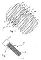
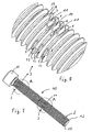
- Figures 1 and 2 show - in a schematic representation - a possible embodiment of a connecting element 1 with thread 2, which is engageable with a (not shown) mating thread.
- the connecting element 1 is designed in the manner of a screw, with a shaft 17 and a head 16.
- the thread 2 of the shaft 17 is formed as a conventional metric thread, which is fully profiled in the shaft 17 is formed.
- the connecting element 1 can also be a threaded rod, a threaded spindle or the like threaded component.
- the invention is not limited to a connecting element with external thread. Rather, the invention also includes female thread leading fasteners.
- the connecting element 1 has means 3 for generating a clamping force acting on the counter-thread (not shown).
- the clamping means 3 of the two embodiments are formed by the flanks 4, 5 and 6, 7 or 8, 9 at least one portion or Windungsabêtes 10 and 11 of the thread 2.
- clamping means 3 of the two embodiments according to FIG. 1 is the arrangement of the opposing flanks 4, 5 and 6, 7 and 8, 9 to each other with respect to the arrangement of the flanks 18, 19 of the thread 2 outside of the clamping portion 10 and 11 changed such that upon engagement of the thread 2 in the (not shown) mating thread, the clamping force on at least one of the flanks 4, 5 and 6, 7 and 8, 9 of the clamping portion 10, 11 is generated.
- the thread 2 in the (not shown) mating thread due to the present clamping force relative movement of the connecting member 1 relative to the (not shown) component with the mating thread prevented and accidental loosening of the screw from thread 2 and (not Pictured) mating thread avoided ,
- the two in FIG. 1 illustrated embodiments of the clamping means 3 differ, inter alia, that in one embodiment, the two flanks 4, 5 of the clamping portion 10 are changed in their arrangement to each other and thus both flanks 4, 5 of the clamping force generation section 10 on the (not shown) counter thread are formed.
- only the edge 6 or 9 of the clamping portion 11 is changed in their arrangement to the other edge 7 and 8 of the clamping portion 11, so that only one edge 6 and 9 of the clamping portion 11 in this case for Klemmkrafter Wegung on the (not shown) counter thread is formed.
- the clamping force generating flanks 4, 5 and 6, 9 of the clamping portions 10, 11 are arranged offset in each case to the outside. Furthermore, the clamping force generating flanks 4, 5 or 6, 9 of the clamping sections 10, 11 are preferably offset from the flanks 18, 19 outside the clamping section 10, 11 substantially parallel to the outside.
- the two embodiments of the clamping means 3 according to FIG. 1 have in common, among other things, that one turn of the thread 2 has a plurality of the clamping portions 10 and 11, respectively.
- the clamping portions 10 and 11 are arranged distributed over the one turn.
- a turn is understood to mean the course of the thread once around the shaft 17 of the connecting element 16.
- each four clamping portions 10 and 11 provided over a turn of the thread 2 and preferably arranged evenly distributed over the winding.
- the invention is not limited to this number of clamping force generating flanks. Rather, 12, 16, 20 and more clamping force generating flanks can be provided over a turn of the thread 2.
- FIGS. 3 and 4 show - in a schematic representation - another embodiment of a connecting element 20.
- FIGS. 3 and 4 which with the features of the connecting element 1 according to the Figures 1 and 2 are identical, are provided with the same reference numerals; in that regard, reference is made to the description of the Figures 1 and 2 directed.
- the connecting element 20 according to the FIGS. 3 and 4 differs from the connecting element 1 according to the Figures 1 and 2 among other things, that the clamping portions 11 are provided on three consecutive turns of the thread 2.
- the mutually facing flanks are adjacent Windings arranged in the same way to each other and preferably form a substantially rectilinear row in the axial direction of the connecting element 20th
- FIGS. 5 and 6 show - in a schematic representation - a yet further embodiment of a connecting element 30.
- the connecting element 30, which with the features of the connecting element 20 according to the FIGS. 3 and 4 and / or the connecting element 1 according to the Figures 1 and 2 are identical, are provided with the same reference numerals; in that regard, reference is made to the description of the Figures 1 and 2 and 3 and 4 referenced.
- the connecting element 30 according to the FIGS. 5 and 6 differs from the connecting element 20 according to the FIGS. 3 and 4 among other things, that the clamping means 3 are arranged in the region of the free end 12 of the shaft 17 of the connecting element 30.
- the first three turns of the thread 2 are provided with the clamping portions 11.
- FIGS. 7 and 8 show a further embodiment of a connecting element 40 with the clamping means 3.
- the connecting element 40 and the clamping means 3, which with the connecting elements 1, 20, 30 according to the FIGS. 1 to 6 are identical, are provided with the same reference numerals; in that regard, reference is made to the description of the FIGS. 1 to 6 directed.
- the connecting element 40 according to the FIGS. 7 and 8 differs from the connecting elements 20 and 30 according to the FIGS. 3 to 6 among other things, the clamping means 3 are arranged on two regions 13, 14 of the thread 2 over a plurality of successive turns of the thread 2. Between the two areas 13, 14 several turns of the thread 2 are provided without such clamping means 3.
- the one region 13 is arranged approximately at the rear end of the shaft 17 of the connecting element 40, which faces the head 16.
- the connecting element 40 according to the FIGS. 7 and 8 differs from the connecting element 20 of the FIGS. 3 and 4 and the connecting member 30 of FIGS. 5 and 6 among other things, that the clamping force generating flanks 6 point in the direction of the free end 12 of the shaft 17 and the clamping force generating flanks 9 in the direction of the head 16 of the connecting element 40.
- FIGS. 9 and 10 show a connecting element 50 in the manner of a screw, in which the clamping means 3 are formed by the clamping portions 10 and additionally by the clamping portions 11.
- the clamping portions 10 and the clamping portions 11 are provided on four consecutive turns of the thread 2.
- the clamping portions 11 are preferably formed on the outer turns, which have only one clamping force-generating edge 7.
- the intermediate turns have the clamping portions 10, in which the two flanks 4, 5 are formed as clamping force generating.
- the clamping portions 10, 11 are arranged distributed over the respective turn.
- the clamping portions 10 and 11 of adjacent turns are in such a way to one another that the clamping portions 10 and 11 in the axial direction of the connecting element 50 form a row, so that depending on the number of clamping portions 10 and 11 per turn there is a corresponding number of rows ,
- a clamping force-generating edge 7 of the clamping portions 11 is formed on that flank of the turn, which faces the subsequent turn with the clamping portions 10.
Landscapes
- Engineering & Computer Science (AREA)
- General Engineering & Computer Science (AREA)
- Mechanical Engineering (AREA)
- Mutual Connection Of Rods And Tubes (AREA)
- Clamps And Clips (AREA)
- Connections By Means Of Piercing Elements, Nuts, Or Screws (AREA)
Claims (14)
- Élément de raccordement (1) comprenant un filetage (2) qui peut être amené en engagement avec un contre-filetage, par exemple d'un écrou, et comprenant des moyens (3) pour générer une force de serrage agissant sur le contre-filetage, les moyens de serrage (3) étant formés par les flancs (4, 5 ; 6, 7, 8, 9) d'au moins une section (10 ; 11) du filetage (2), dont la disposition les uns par rapport aux autres peut être modifiée par rapport à la disposition des flancs (18, 19) du filetage (2) en dehors de la section de serrage (10 ; 11) de telle sorte que, lors de l'engagement du filetage (2) dans le contre-filetage, la force de serrage soit générée sur au moins l'un des flancs (4, 5 ; 6, 7, 8, 9) de la section de serrage (10 ; 11), caractérisé en ce qu'au moins une spire dépourvue de moyen serrage se situe entre les spires dotées de moyens de serrage (3).
- Élément de raccordement selon la revendication 1, caractérisé en ce que les flancs (4, 5 ; 6, 7, 8, 9) de l'au moins une section de serrage (10 ; 11) sont disposés les uns par rapport aux autres de telle sorte que, dans l'état engagé du filetage ( 2 ) et du contre-filetage, l'élément de raccordement (1) soit maintenu de manière bloquée en rotation dans le contre-filetage.
- Élément de raccordement selon la revendication 1 ou 2, caractérisé en ce que la disposition de l'un des flancs (6, 7, 8, 9) de l'au moins une section de serrage (11) par rapport à l'autre flanc (7, 8) de la section de serrage (11) est modifiée.
- Élément de raccordement selon la revendication 1 ou 2, caractérisé en ce que la disposition l'un par rapport à l'autre des deux flancs (4, 5) de la section de serrage (10) est modifiée.
- Élément de raccordement selon l'une quelconque des revendications précédentes, caractérisé en ce que l'au moins un flanc (4, 5 ; 6, 9) générant une force de serrage de la section de serrage (10 ; 11) est décalé vers l'extérieur.
- Élément de raccordement selon l'une quelconque des revendications précédentes, caractérisé en ce que l'au moins un flanc (4, 5 ; 6, 9) générant une force de serrage est décalé essentiellement parallèlement par rapport au flanc (18, 19) en dehors de la section de serrage (10 ; 11 ; 10, 11).
- Élément de raccordement selon l'une quelconque des revendications précédentes, caractérisé en ce que la section de serrage s'étend sur au moins une spire du filetage (2).
- Élément de raccordement selon l'une quelconque des revendications 1 à 6, caractérisé en ce qu'une spire du filetage (2) comprend plusieurs sections de serrage (10 ; 11) qui sont de préférence disposées de manière répartie sur la spire.
- Élément de raccordement selon l'une quelconque des revendications précédentes, caractérisé en ce que lorsqu'une spire du filetage (2) présente plusieurs sections de serrage (11), l'un des flancs (6, 7, 8, 9) de la section de serrage (11) respective forme le flanc (6, 9) générant une force de serrage.
- Élément de raccordement selon la revendication 9, caractérisé en ce que l'un des deux flancs (6, 7, 8, 9) des sections de serrage (11) respectives forme en alternance le flanc (6, 9) générant une force de serrage.
- Élément de raccordement selon l'une quelconque des revendications précédentes, caractérisé en ce qu'au moins deux spires consécutives du filetage (2) comprennent des sections de serrage (10 ; 11 ; 10, 11).
- Élément de raccordement selon la revendication 11, caractérisé en ce que les flancs se faisant face de spires adjacentes forment les flancs (6, 9) générant une force de serrage des sections de serrage (11).
- Élément de raccordement selon la revendication 11 ou 12, caractérisé en ce que les flancs (6, 9) générant une force de serrage de spires adjacentes sont disposés de manière décalée les uns par rapport aux autres.
- Raccordement vissé doté d'un élément de raccordement (1) selon l'une quelconque des revendications précédentes et doté d'une pièce structurale comprenant un contre-filetage, en particulier un écrou ou une pièce en forme de plaque dont le contre-filetage est amené en engagement avec le filetage (2) de l'élément de raccordement (1).
Applications Claiming Priority (1)
| Application Number | Priority Date | Filing Date | Title |
|---|---|---|---|
| DE102008027297A DE102008027297A1 (de) | 2008-06-06 | 2008-06-06 | Verbindungselement für eine Schraubverbindung sowie eine solche Schraubverbindung |
Publications (3)
| Publication Number | Publication Date |
|---|---|
| EP2131048A2 EP2131048A2 (fr) | 2009-12-09 |
| EP2131048A3 EP2131048A3 (fr) | 2010-05-26 |
| EP2131048B1 true EP2131048B1 (fr) | 2012-04-25 |
Family
ID=41016911
Family Applications (1)
| Application Number | Title | Priority Date | Filing Date |
|---|---|---|---|
| EP09007513A Not-in-force EP2131048B1 (fr) | 2008-06-06 | 2009-06-06 | Elément de verrouillage pour un raccordement de vis et raccordement de vis correspondant |
Country Status (5)
| Country | Link |
|---|---|
| US (1) | US8038376B2 (fr) |
| EP (1) | EP2131048B1 (fr) |
| AT (1) | ATE555314T1 (fr) |
| DE (1) | DE102008027297A1 (fr) |
| ES (1) | ES2390518T3 (fr) |
Cited By (1)
| Publication number | Priority date | Publication date | Assignee | Title |
|---|---|---|---|---|
| DE102015119305A1 (de) * | 2015-11-10 | 2017-05-11 | Bürkert Werke GmbH | Ventillinearantrieb sowie Ventil |
Families Citing this family (14)
| Publication number | Priority date | Publication date | Assignee | Title |
|---|---|---|---|---|
| DE102010037757A1 (de) | 2010-09-24 | 2012-03-29 | Pee-Wee Kaltwalz- Und Rohrbearbeitungsmaschinen Gmbh | Gewinde mit zumindest einem Klemmabschnitt |
| DE102011100246A1 (de) * | 2011-05-02 | 2012-11-08 | Pierburg Gmbh | Sicherungsschraube für eine Schraubverbindung |
| DE202013011706U1 (de) * | 2013-03-06 | 2014-03-25 | Norma Germany Gmbh | Schellen-Schraubverbindung, insbesondere für eine Schelle, und Schelle |
| DE102014214788A1 (de) * | 2014-07-28 | 2016-01-28 | Robert Bosch Gmbh | Hochdruckanschlussvorrichtung, Verfahren und Werkzeug zur Herstellung einer Hochdruckanschlussvorrichtung und Kraftstoffeinspritzventil mit einer Hochdruckanschlussvorrichtung |
| JP3194854U (ja) * | 2014-09-30 | 2014-12-11 | イワタボルト株式会社 | ボルト |
| USD739220S1 (en) * | 2014-09-30 | 2015-09-22 | Lee Valley Tools Ltd. | Wall fastener |
| USD803038S1 (en) * | 2015-12-08 | 2017-11-21 | Automatic Bar Controls, Inc. | Low profile, non-slotted, easily cleanable fastener for food splash zones or food-contact surfaces of cruise vessels |
| US20180051737A1 (en) * | 2016-08-18 | 2018-02-22 | Research Engineering & Manufacturing Inc. | High performance thread rolling and thread locking fastener |
| AT519474B1 (de) * | 2017-04-25 | 2018-07-15 | Avvio Gmbh & Co Kg | Holzschraube |
| USD843488S1 (en) * | 2017-10-09 | 2019-03-19 | Wist Work Llc | Spinning disc and spindle toy |
| JP6673540B2 (ja) * | 2018-01-19 | 2020-03-25 | 日本精工株式会社 | ナット、送りねじ機構およびステアリングホイールの電動位置調節装置 |
| US11015637B2 (en) * | 2018-04-06 | 2021-05-25 | A. Raymond Et Cie | Leveling bolt and related methods |
| USD992039S1 (en) * | 2021-03-03 | 2023-07-11 | ARK Therapeutic Services, Inc. | Fidget device for sensory therapy |
| US12540640B2 (en) * | 2021-03-03 | 2026-02-03 | Process Displays Llc | Threaded fastener and connector |
Family Cites Families (20)
| Publication number | Priority date | Publication date | Assignee | Title |
|---|---|---|---|---|
| US2581690A (en) | 1949-11-30 | 1952-01-08 | Moehle Walter | Locking thread structure |
| USRE27678E (en) * | 1968-05-03 | 1973-06-19 | Self-locking screws | |
| US3687183A (en) | 1970-06-30 | 1972-08-29 | Threadline Fastener Corp | Self-locking screw threaded fastener |
| US3789644A (en) | 1971-11-22 | 1974-02-05 | Litton Industrial Products | Self-locking dies for making threads |
| US3850215A (en) | 1971-11-22 | 1974-11-26 | Litton Industrial Products | Self-locking fasteners |
| US3972361A (en) * | 1972-05-30 | 1976-08-03 | Standard Pressed Steel Co. | Threaded fastener |
| US3982575A (en) * | 1974-12-23 | 1976-09-28 | Standard Pressed Steel Co. | Thread forming self-locking screw |
| US4653968A (en) * | 1980-08-25 | 1987-03-31 | Illinois Tool Works, Inc. | Adjustable abutment assembly |
| JPS57110812A (en) * | 1980-12-26 | 1982-07-09 | Nissan Motor | Clamp and its manufacture |
| DE4039402A1 (de) | 1990-12-10 | 1992-06-11 | Itw Ateco Gmbh | Schraube mit selbstsicherndem gewinde |
| US5141376A (en) * | 1992-02-03 | 1992-08-25 | Emhart Inc. | Self drilling screw |
| US6224237B1 (en) * | 1998-04-16 | 2001-05-01 | Honeywell International Inc. | Structure for achieving a linear light source geometry |
| US7156600B2 (en) * | 2001-06-19 | 2007-01-02 | Illinois Tool Works Inc. | Die for, method of making, and fastener with lobed primary thread lead and interposed dual auxiliary thread lead with improved substrate entry end portion |
| US6974289B2 (en) * | 2002-08-12 | 2005-12-13 | Illinois Tool Works Inc | Pressure flank screw and fastening system therewith |
| US6976818B2 (en) * | 2002-08-12 | 2005-12-20 | Illinois Tool Works Inc. | Threaded fastener particularly suited for plastics |
| DE10238055B4 (de) | 2002-08-20 | 2004-10-28 | Ejot Gmbh & Co. Kg | Mit selbstklemmendem Gewinde versehene Schraube |
| JP2007016797A (ja) * | 2002-11-29 | 2007-01-25 | Imasen Electric Ind Co Ltd | マルチピッチねじとマルチピッチナットとの組み合わせ及びマルチピッチナットの製造方法。 |
| US7338243B2 (en) * | 2003-02-18 | 2008-03-04 | Toge-Dübel A. Gerhard KG | Thread-cutting screw |
| US7163366B2 (en) * | 2005-01-05 | 2007-01-16 | Pei-Hua Chen | Screw with two types of threads |
| DE102005041586A1 (de) | 2005-09-01 | 2007-03-08 | Ejot Gmbh & Co. Kg | Gewindefurchende Schraube |
-
2008
- 2008-06-06 DE DE102008027297A patent/DE102008027297A1/de not_active Withdrawn
- 2008-09-29 US US12/240,340 patent/US8038376B2/en not_active Expired - Fee Related
-
2009
- 2009-06-06 ES ES09007513T patent/ES2390518T3/es active Active
- 2009-06-06 EP EP09007513A patent/EP2131048B1/fr not_active Not-in-force
- 2009-06-06 AT AT09007513T patent/ATE555314T1/de active
Cited By (1)
| Publication number | Priority date | Publication date | Assignee | Title |
|---|---|---|---|---|
| DE102015119305A1 (de) * | 2015-11-10 | 2017-05-11 | Bürkert Werke GmbH | Ventillinearantrieb sowie Ventil |
Also Published As
| Publication number | Publication date |
|---|---|
| ATE555314T1 (de) | 2012-05-15 |
| DE102008027297A1 (de) | 2009-12-10 |
| EP2131048A2 (fr) | 2009-12-09 |
| US20090304478A1 (en) | 2009-12-10 |
| ES2390518T3 (es) | 2012-11-13 |
| EP2131048A3 (fr) | 2010-05-26 |
| US8038376B2 (en) | 2011-10-18 |
Similar Documents
| Publication | Publication Date | Title |
|---|---|---|
| EP2131048A2 (fr) | Elément de verrouillage pour un raccordement de vis et raccordement de vis correspondant | |
| EP3004666B1 (fr) | Vis | |
| EP0381980B1 (fr) | Dispositif de fixation et de traversée de câbles, conduites ou tuyaux | |
| DE2452825C2 (de) | Schraube | |
| DE3610392C2 (de) | Schraube für verunreinigte Gewindebohrungen | |
| DE2457143C3 (de) | Sicherungsschraube | |
| EP1020652A2 (fr) | Elément de fixation pour deux organes de machine ou deux pièces de construction, notamment vis d'ajustage extensible, boulon d'ajustage, etc | |
| DE3115620A1 (de) | Selbsthemmende schraubverbindung und werkzeug zur herstellung eines aussengewindes | |
| DE2645519C2 (de) | Selbsthemmendes Gewinde | |
| DE102012110986A1 (de) | Gewindeanordnung und Verfahren zum Montieren der Gewindeanordnung | |
| DE112005002820T5 (de) | Schraube mit mehreren Gewindesteigungen, Verfahren und Vorrichtung zum Herstellen einer Schraube mit mehreren Gewindesteigungen | |
| DE2521684A1 (de) | Erschuetterungssicheres befestigungselement | |
| DE69406905T2 (de) | Befestigungselement und schraubvorrichtung dafür | |
| DE102019207681A1 (de) | Verbindungselement | |
| DE102016101910A1 (de) | Kunststoff-Gewindeelement sowie Verbindungsanordnung bestehend aus einem Kunststoffträgerteil und einem Kunststoff-Gewindeelement | |
| EP2224143B1 (fr) | Ecrou, raccordement de vis, connexion de profilé, ainsi que procédé de fabrication d'un écrou | |
| DE69105433T2 (de) | Selbsthaltendes Befestigungselement. | |
| EP4416399B1 (fr) | Contre-écrou comprenant un élément de sécurité | |
| DE102013203150A1 (de) | Verfahren zum Herstellen einer Betonschraube | |
| WO2015172968A1 (fr) | Dispositif pour empêcher le détachement intempestif d'un élément de serrage | |
| DE1750206B2 (de) | In ein normalgewinde einschraubbarer schraubbolzen mit sicherungsgewinde | |
| EP0441224B1 (fr) | Taraudage auto-blocant | |
| DE4231339C2 (de) | Vorrichtung zum Paßzentrieren und Paßverbinden von Teilen | |
| EP0568106A1 (fr) | Filetape autobloquant | |
| DE102015111456A1 (de) | Schraube für eine elektrische Kontaktverbindung |
Legal Events
| Date | Code | Title | Description |
|---|---|---|---|
| PUAI | Public reference made under article 153(3) epc to a published international application that has entered the european phase |
Free format text: ORIGINAL CODE: 0009012 |
|
| AK | Designated contracting states |
Kind code of ref document: A2 Designated state(s): AT BE BG CH CY CZ DE DK EE ES FI FR GB GR HR HU IE IS IT LI LT LU LV MC MK MT NL NO PL PT RO SE SI SK TR |
|
| PUAL | Search report despatched |
Free format text: ORIGINAL CODE: 0009013 |
|
| AK | Designated contracting states |
Kind code of ref document: A3 Designated state(s): AT BE BG CH CY CZ DE DK EE ES FI FR GB GR HR HU IE IS IT LI LT LU LV MC MK MT NL NO PL PT RO SE SI SK TR |
|
| AX | Request for extension of the european patent |
Extension state: AL BA RS |
|
| RIC1 | Information provided on ipc code assigned before grant |
Ipc: F16B 33/02 20060101ALI20100420BHEP Ipc: F16B 39/30 20060101AFI20090907BHEP |
|
| 17P | Request for examination filed |
Effective date: 20100904 |
|
| 17Q | First examination report despatched |
Effective date: 20110520 |
|
| GRAP | Despatch of communication of intention to grant a patent |
Free format text: ORIGINAL CODE: EPIDOSNIGR1 |
|
| GRAS | Grant fee paid |
Free format text: ORIGINAL CODE: EPIDOSNIGR3 |
|
| GRAA | (expected) grant |
Free format text: ORIGINAL CODE: 0009210 |
|
| AK | Designated contracting states |
Kind code of ref document: B1 Designated state(s): AT BE BG CH CY CZ DE DK EE ES FI FR GB GR HR HU IE IS IT LI LT LU LV MC MK MT NL NO PL PT RO SE SI SK TR |
|
| REG | Reference to a national code |
Ref country code: GB Ref legal event code: FG4D Free format text: NOT ENGLISH |
|
| REG | Reference to a national code |
Ref country code: CH Ref legal event code: EP |
|
| REG | Reference to a national code |
Ref country code: AT Ref legal event code: REF Ref document number: 555314 Country of ref document: AT Kind code of ref document: T Effective date: 20120515 |
|
| REG | Reference to a national code |
Ref country code: IE Ref legal event code: FG4D Free format text: LANGUAGE OF EP DOCUMENT: GERMAN |
|
| REG | Reference to a national code |
Ref country code: DE Ref legal event code: R096 Ref document number: 502009003321 Country of ref document: DE Effective date: 20120621 |
|
| REG | Reference to a national code |
Ref country code: NL Ref legal event code: VDEP Effective date: 20120425 |
|
| LTIE | Lt: invalidation of european patent or patent extension |
Effective date: 20120425 |
|
| PG25 | Lapsed in a contracting state [announced via postgrant information from national office to epo] |
Ref country code: NO Free format text: LAPSE BECAUSE OF FAILURE TO SUBMIT A TRANSLATION OF THE DESCRIPTION OR TO PAY THE FEE WITHIN THE PRESCRIBED TIME-LIMIT Effective date: 20120725 Ref country code: SE Free format text: LAPSE BECAUSE OF FAILURE TO SUBMIT A TRANSLATION OF THE DESCRIPTION OR TO PAY THE FEE WITHIN THE PRESCRIBED TIME-LIMIT Effective date: 20120425 Ref country code: LT Free format text: LAPSE BECAUSE OF FAILURE TO SUBMIT A TRANSLATION OF THE DESCRIPTION OR TO PAY THE FEE WITHIN THE PRESCRIBED TIME-LIMIT Effective date: 20120425 Ref country code: FI Free format text: LAPSE BECAUSE OF FAILURE TO SUBMIT A TRANSLATION OF THE DESCRIPTION OR TO PAY THE FEE WITHIN THE PRESCRIBED TIME-LIMIT Effective date: 20120425 Ref country code: CY Free format text: LAPSE BECAUSE OF FAILURE TO SUBMIT A TRANSLATION OF THE DESCRIPTION OR TO PAY THE FEE WITHIN THE PRESCRIBED TIME-LIMIT Effective date: 20120425 Ref country code: IS Free format text: LAPSE BECAUSE OF FAILURE TO SUBMIT A TRANSLATION OF THE DESCRIPTION OR TO PAY THE FEE WITHIN THE PRESCRIBED TIME-LIMIT Effective date: 20120825 Ref country code: PL Free format text: LAPSE BECAUSE OF FAILURE TO SUBMIT A TRANSLATION OF THE DESCRIPTION OR TO PAY THE FEE WITHIN THE PRESCRIBED TIME-LIMIT Effective date: 20120425 |
|
| REG | Reference to a national code |
Ref country code: ES Ref legal event code: FG2A Ref document number: 2390518 Country of ref document: ES Kind code of ref document: T3 Effective date: 20121113 |
|
| PG25 | Lapsed in a contracting state [announced via postgrant information from national office to epo] |
Ref country code: HR Free format text: LAPSE BECAUSE OF FAILURE TO SUBMIT A TRANSLATION OF THE DESCRIPTION OR TO PAY THE FEE WITHIN THE PRESCRIBED TIME-LIMIT Effective date: 20120425 Ref country code: GR Free format text: LAPSE BECAUSE OF FAILURE TO SUBMIT A TRANSLATION OF THE DESCRIPTION OR TO PAY THE FEE WITHIN THE PRESCRIBED TIME-LIMIT Effective date: 20120726 Ref country code: LV Free format text: LAPSE BECAUSE OF FAILURE TO SUBMIT A TRANSLATION OF THE DESCRIPTION OR TO PAY THE FEE WITHIN THE PRESCRIBED TIME-LIMIT Effective date: 20120425 Ref country code: PT Free format text: LAPSE BECAUSE OF FAILURE TO SUBMIT A TRANSLATION OF THE DESCRIPTION OR TO PAY THE FEE WITHIN THE PRESCRIBED TIME-LIMIT Effective date: 20120827 Ref country code: SI Free format text: LAPSE BECAUSE OF FAILURE TO SUBMIT A TRANSLATION OF THE DESCRIPTION OR TO PAY THE FEE WITHIN THE PRESCRIBED TIME-LIMIT Effective date: 20120425 |
|
| BERE | Be: lapsed |
Owner name: PEE-WEE KALTWALZ- UND ROHRBEARBEITUNGSMASCHINEN G Effective date: 20120630 |
|
| PG25 | Lapsed in a contracting state [announced via postgrant information from national office to epo] |
Ref country code: RO Free format text: LAPSE BECAUSE OF FAILURE TO SUBMIT A TRANSLATION OF THE DESCRIPTION OR TO PAY THE FEE WITHIN THE PRESCRIBED TIME-LIMIT Effective date: 20120425 Ref country code: CZ Free format text: LAPSE BECAUSE OF FAILURE TO SUBMIT A TRANSLATION OF THE DESCRIPTION OR TO PAY THE FEE WITHIN THE PRESCRIBED TIME-LIMIT Effective date: 20120425 Ref country code: MC Free format text: LAPSE BECAUSE OF NON-PAYMENT OF DUE FEES Effective date: 20120630 Ref country code: SK Free format text: LAPSE BECAUSE OF FAILURE TO SUBMIT A TRANSLATION OF THE DESCRIPTION OR TO PAY THE FEE WITHIN THE PRESCRIBED TIME-LIMIT Effective date: 20120425 Ref country code: EE Free format text: LAPSE BECAUSE OF FAILURE TO SUBMIT A TRANSLATION OF THE DESCRIPTION OR TO PAY THE FEE WITHIN THE PRESCRIBED TIME-LIMIT Effective date: 20120425 Ref country code: NL Free format text: LAPSE BECAUSE OF FAILURE TO SUBMIT A TRANSLATION OF THE DESCRIPTION OR TO PAY THE FEE WITHIN THE PRESCRIBED TIME-LIMIT Effective date: 20120425 Ref country code: DK Free format text: LAPSE BECAUSE OF FAILURE TO SUBMIT A TRANSLATION OF THE DESCRIPTION OR TO PAY THE FEE WITHIN THE PRESCRIBED TIME-LIMIT Effective date: 20120425 |
|
| PG25 | Lapsed in a contracting state [announced via postgrant information from national office to epo] |
Ref country code: MK Free format text: LAPSE BECAUSE OF FAILURE TO SUBMIT A TRANSLATION OF THE DESCRIPTION OR TO PAY THE FEE WITHIN THE PRESCRIBED TIME-LIMIT Effective date: 20120425 Ref country code: IT Free format text: LAPSE BECAUSE OF FAILURE TO SUBMIT A TRANSLATION OF THE DESCRIPTION OR TO PAY THE FEE WITHIN THE PRESCRIBED TIME-LIMIT Effective date: 20120425 |
|
| PLBE | No opposition filed within time limit |
Free format text: ORIGINAL CODE: 0009261 |
|
| STAA | Information on the status of an ep patent application or granted ep patent |
Free format text: STATUS: NO OPPOSITION FILED WITHIN TIME LIMIT |
|
| REG | Reference to a national code |
Ref country code: IE Ref legal event code: MM4A |
|
| 26N | No opposition filed |
Effective date: 20130128 |
|
| PG25 | Lapsed in a contracting state [announced via postgrant information from national office to epo] |
Ref country code: BE Free format text: LAPSE BECAUSE OF NON-PAYMENT OF DUE FEES Effective date: 20120630 Ref country code: IE Free format text: LAPSE BECAUSE OF NON-PAYMENT OF DUE FEES Effective date: 20120606 |
|
| REG | Reference to a national code |
Ref country code: DE Ref legal event code: R097 Ref document number: 502009003321 Country of ref document: DE Effective date: 20130128 |
|
| PG25 | Lapsed in a contracting state [announced via postgrant information from national office to epo] |
Ref country code: BG Free format text: LAPSE BECAUSE OF FAILURE TO SUBMIT A TRANSLATION OF THE DESCRIPTION OR TO PAY THE FEE WITHIN THE PRESCRIBED TIME-LIMIT Effective date: 20120725 Ref country code: MT Free format text: LAPSE BECAUSE OF FAILURE TO SUBMIT A TRANSLATION OF THE DESCRIPTION OR TO PAY THE FEE WITHIN THE PRESCRIBED TIME-LIMIT Effective date: 20120425 |
|
| REG | Reference to a national code |
Ref country code: CH Ref legal event code: PL |
|
| GBPC | Gb: european patent ceased through non-payment of renewal fee |
Effective date: 20130606 |
|
| PG25 | Lapsed in a contracting state [announced via postgrant information from national office to epo] |
Ref country code: LI Free format text: LAPSE BECAUSE OF NON-PAYMENT OF DUE FEES Effective date: 20130630 Ref country code: TR Free format text: LAPSE BECAUSE OF FAILURE TO SUBMIT A TRANSLATION OF THE DESCRIPTION OR TO PAY THE FEE WITHIN THE PRESCRIBED TIME-LIMIT Effective date: 20120425 Ref country code: GB Free format text: LAPSE BECAUSE OF NON-PAYMENT OF DUE FEES Effective date: 20130606 Ref country code: CH Free format text: LAPSE BECAUSE OF NON-PAYMENT OF DUE FEES Effective date: 20130630 |
|
| PG25 | Lapsed in a contracting state [announced via postgrant information from national office to epo] |
Ref country code: LU Free format text: LAPSE BECAUSE OF NON-PAYMENT OF DUE FEES Effective date: 20120606 |
|
| PG25 | Lapsed in a contracting state [announced via postgrant information from national office to epo] |
Ref country code: HU Free format text: LAPSE BECAUSE OF FAILURE TO SUBMIT A TRANSLATION OF THE DESCRIPTION OR TO PAY THE FEE WITHIN THE PRESCRIBED TIME-LIMIT Effective date: 20090606 |
|
| REG | Reference to a national code |
Ref country code: FR Ref legal event code: PLFP Year of fee payment: 7 |
|
| PGFP | Annual fee paid to national office [announced via postgrant information from national office to epo] |
Ref country code: ES Payment date: 20150626 Year of fee payment: 7 |
|
| REG | Reference to a national code |
Ref country code: AT Ref legal event code: MM01 Ref document number: 555314 Country of ref document: AT Kind code of ref document: T Effective date: 20140606 |
|
| PGFP | Annual fee paid to national office [announced via postgrant information from national office to epo] |
Ref country code: FR Payment date: 20150619 Year of fee payment: 7 |
|
| PG25 | Lapsed in a contracting state [announced via postgrant information from national office to epo] |
Ref country code: AT Free format text: LAPSE BECAUSE OF NON-PAYMENT OF DUE FEES Effective date: 20140606 |
|
| PGFP | Annual fee paid to national office [announced via postgrant information from national office to epo] |
Ref country code: DE Payment date: 20160630 Year of fee payment: 8 |
|
| REG | Reference to a national code |
Ref country code: FR Ref legal event code: ST Effective date: 20170228 |
|
| PG25 | Lapsed in a contracting state [announced via postgrant information from national office to epo] |
Ref country code: FR Free format text: LAPSE BECAUSE OF NON-PAYMENT OF DUE FEES Effective date: 20160630 |
|
| REG | Reference to a national code |
Ref country code: DE Ref legal event code: R119 Ref document number: 502009003321 Country of ref document: DE |
|
| PG25 | Lapsed in a contracting state [announced via postgrant information from national office to epo] |
Ref country code: DE Free format text: LAPSE BECAUSE OF NON-PAYMENT OF DUE FEES Effective date: 20180103 |
|
| PG25 | Lapsed in a contracting state [announced via postgrant information from national office to epo] |
Ref country code: ES Free format text: LAPSE BECAUSE OF NON-PAYMENT OF DUE FEES Effective date: 20160607 |
|
| REG | Reference to a national code |
Ref country code: ES Ref legal event code: FD2A Effective date: 20180622 |