EP2131221A1 - Verfahren zur Ausrichtung von Kunststoffglasfasern - Google Patents
Verfahren zur Ausrichtung von Kunststoffglasfasern Download PDFInfo
- Publication number
- EP2131221A1 EP2131221A1 EP08157544A EP08157544A EP2131221A1 EP 2131221 A1 EP2131221 A1 EP 2131221A1 EP 08157544 A EP08157544 A EP 08157544A EP 08157544 A EP08157544 A EP 08157544A EP 2131221 A1 EP2131221 A1 EP 2131221A1
- Authority
- EP
- European Patent Office
- Prior art keywords
- plastic optical
- fibers
- optical fibers
- optical fiber
- aligner
- Prior art date
- Legal status (The legal status is an assumption and is not a legal conclusion. Google has not performed a legal analysis and makes no representation as to the accuracy of the status listed.)
- Withdrawn
Links
Images


Classifications
-
- G—PHYSICS
- G02—OPTICS
- G02B—OPTICAL ELEMENTS, SYSTEMS OR APPARATUS
- G02B6/00—Light guides; Structural details of arrangements comprising light guides and other optical elements, e.g. couplings
- G02B6/24—Coupling light guides
- G02B6/26—Optical coupling means
Definitions
- the present invention relates to a method for plastic optical fiber alignment and, in particular, to a method for plastic optical fiber alignment that can be used for precisely aligning the fibers of two plastic optical fibers by means of an aligner having a positioning space therein provided with the function of correction.
- optical fiber Since current requirement for the channel bandwidth for data or signal transmission is increasingly strong, the technology of optical fiber was developed.
- the optical fiber is becoming an important medium for network transmission, advantageously characterized by low loss, wide band, non-conductivity, non-inductivity, small size, small bending radius and small weight, etc.
- Optical fibers have been applied widely to network transmission. Due to the finite length of an optical fiber, another plastic optical fiber is needed to connect if the present one is not long sufficiently. Thus, the plastic optical fiber can have its length increased to reach where the network is to be established.
- plastic optical fibers are aligned cannot be popular one, however. It is rather difficult to align two plastic optical fibers as an entirety. Even though the plastic optical fibers are fusion-spliced to be aligned each other, it is very inconvenient for the operation in situ; moreover, fusion-splicing equipment is very complicated and expensive.
- the primary objective of the present invention is to provide a method for plastic optical fiber alignment that can be used for precisely aligning the fibers of two plastic optical fibers by means of an aligner having a positioning space therein provided with function of correction.
- Another objective of the present invention is to provide a method for plastic optical fiber alignment characterized in that the fibers of two plastic optical fibers can be precisely aligned with each other so as to reduce optical transport loss as well as to reduce insertion loss.
- a method for plastic optical fiber alignment that can fulfill the above objectives is performed with an aligner and two plastic optical fibers.
- the aligner has a positioning space disposed therein, which is provided with the function of correction for fiber alignment, and a first and a second inlets each disposed on a respective side thereof and communicating with the positioning space.
- the cladding at an end of each one of the two plastic optical fibers is removed so that the fibers of the plastic optical fibers are bare.
- the two plastic optical fibers can be inserted into the aligner, respectively via the first and the second inlets, till the fibers of the two plastic optical fibers are put in the positioning space, which can be used for correcting the fibers so as to precisely align the fibers.
- the present method is characterized in that the fibers of two plastic optical fibers can be precisely aligned with each other so as to reduce optical transport loss as well as to avoid alignment offset.
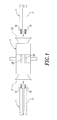
- the first step is to provide an aligner 2, which has a first inlet 21 and a second inlet 22 each disposed on a respective side thereof and has a positioning space 23 disposed therein and communicating with the inlets 21, 22.
- the second step is to remove the cladding at an end of each one of at least two plastic optical fibers 1, so as to bare the end fiber 12 of the plastic optical fiber 1.
- the third step is to put the at least two plastic optical fibers 1 with bare end fibers 12 into the aligner 2, respectively via the first inlet 21 and the second inlet 22, and position the at least two plastic optical fibers 1 in the positioning space 23 so as to precisely align the fibers 12 of the at least two plastic optical fibers 1, wherein the fibers 12 of the at least two plastic optical fibers 1 are bonded or almost bonded at the end faces thereof to be aligned with each other.
- the plastic optical fiber alignment can be accomplished according to the flow of processes as described above.
- FIG. 4 and FIG 5 are views for another one embodiment of the method for plastic optical fiber alignment.
- the step of removing the cladding 11 at an end of the plastic optical fiber 1 is skipped.
- the step is performed of inserting the at least two plastic optical fibers 1, respectively via the inlets 21, 22 of the aligner 2, till the at least two plastic optical fibers 1 are put in the positioning space 23.
- the positioning space 23 can be used for correcting the claddings 11 of the plastic optical fibers 1, so that the at least two plastic optical fibers 1 have the fibers 12 aligned directly or indirectly through the claddings 11.
- either the fibers 12 or the claddings 11 can be aligned with each other, whose positions are then corrected by using the positioning space 23. Both ways of plastic optical fiber alignment can make the fibers 12 precisely aligned directly or indirectly.
- the present invention is characterized by this precise alignment with each other so as to achieve excellent optical transport.
- the plastic optical fibers 1 being twin-core fibers are only those used in preferable embodiments, but not for limiting the scope, of the present invention. Single-core fibers or multiple-core fibers can be used as well.
- the method for plastic optical fiber alignment provided by the present invention as compared with conventional technologies, has the following advantages.
Landscapes
- Physics & Mathematics (AREA)
- General Physics & Mathematics (AREA)
- Optics & Photonics (AREA)
- Mechanical Coupling Of Light Guides (AREA)
Priority Applications (1)
| Application Number | Priority Date | Filing Date | Title |
|---|---|---|---|
| EP08157544A EP2131221A1 (de) | 2008-06-04 | 2008-06-04 | Verfahren zur Ausrichtung von Kunststoffglasfasern |
Applications Claiming Priority (1)
| Application Number | Priority Date | Filing Date | Title |
|---|---|---|---|
| EP08157544A EP2131221A1 (de) | 2008-06-04 | 2008-06-04 | Verfahren zur Ausrichtung von Kunststoffglasfasern |
Publications (1)
| Publication Number | Publication Date |
|---|---|
| EP2131221A1 true EP2131221A1 (de) | 2009-12-09 |
Family
ID=39789875
Family Applications (1)
| Application Number | Title | Priority Date | Filing Date |
|---|---|---|---|
| EP08157544A Withdrawn EP2131221A1 (de) | 2008-06-04 | 2008-06-04 | Verfahren zur Ausrichtung von Kunststoffglasfasern |
Country Status (1)
| Country | Link |
|---|---|
| EP (1) | EP2131221A1 (de) |
Citations (2)
| Publication number | Priority date | Publication date | Assignee | Title |
|---|---|---|---|---|
| EP0063954A1 (de) * | 1981-04-27 | 1982-11-03 | RAYCHEM CORPORATION (a Delaware corporation) | Verfahren, Gerät und Artikel für fiberoptische Systeme |
| EP1686402A1 (de) * | 2003-11-19 | 2006-08-02 | Tomoegawa Paper Co. Ltd. | Optische verbindungsstruktur und optisches verbindungsverfahren |
-
2008
- 2008-06-04 EP EP08157544A patent/EP2131221A1/de not_active Withdrawn
Patent Citations (2)
| Publication number | Priority date | Publication date | Assignee | Title |
|---|---|---|---|---|
| EP0063954A1 (de) * | 1981-04-27 | 1982-11-03 | RAYCHEM CORPORATION (a Delaware corporation) | Verfahren, Gerät und Artikel für fiberoptische Systeme |
| EP1686402A1 (de) * | 2003-11-19 | 2006-08-02 | Tomoegawa Paper Co. Ltd. | Optische verbindungsstruktur und optisches verbindungsverfahren |
Similar Documents
| Publication | Publication Date | Title |
|---|---|---|
| US7985026B1 (en) | Guiding connector for optical fiber extension | |
| US10324262B1 (en) | Field terminable fiber optic connectors | |
| CN115774305B (zh) | 一种光纤连接器和光纤插芯制备方法 | |
| CN104204882B (zh) | 平面光波导及其制造方法 | |
| WO2009075168A1 (ja) | 光デバイス及びレンズアッセンブリ | |
| CN105408789A (zh) | 用于光学连接器的插芯 | |
| CN103718075B (zh) | 包括其内具有稳定光纤长度的连接器的光缆组件 | |
| WO2007019460A3 (en) | Linear fiber array mount to a spectrometer | |
| US7567743B1 (en) | Field terminating method and device | |
| JP5916095B2 (ja) | 光ファイバの接続機構およびその方法 | |
| EP2131221A1 (de) | Verfahren zur Ausrichtung von Kunststoffglasfasern | |
| US8111967B2 (en) | Mechanical splice | |
| US7563034B2 (en) | Anti-wiggle optical receptacle | |
| US9541712B2 (en) | Optical fiber connector assembling device | |
| JP2005284150A (ja) | コア拡大光ファイバの製造方法、光ファイバ、及び光コネクタ | |
| WO2007068111A3 (en) | An apparatus and method for determining stray light emitted by a mechanical splice | |
| EP3054333A1 (de) | Optischer adapter zur montage an einem adapter zum optischen verbinden anschlussfertiger optischer kabel | |
| US20040252941A1 (en) | Micro-optic fiber device | |
| US8419290B2 (en) | Optical fiber fixing device and method for assembling optical fiber to optical connector using same | |
| WO2004008214A1 (ja) | 光ファイバ接続用部品、光ファイバ接続構造および光ファイバ接続方法 | |
| EP2138880A1 (de) | Kopplungsstruktur für Plastikfaserkabel | |
| JP4542824B2 (ja) | 光学接続構造及び光学接続構造の作製方法 | |
| WO2020081428A1 (en) | Ferruled fiber optic connectors and methods for positioning optical fibers in ferrules | |
| US20110299818A1 (en) | Method and apparatus for mechanically splicing two optic fibers | |
| US7490995B1 (en) | Optical connector assembly |
Legal Events
| Date | Code | Title | Description |
|---|---|---|---|
| PUAI | Public reference made under article 153(3) epc to a published international application that has entered the european phase |
Free format text: ORIGINAL CODE: 0009012 |
|
| AK | Designated contracting states |
Kind code of ref document: A1 Designated state(s): AT BE BG CH CY CZ DE DK EE ES FI FR GB GR HR HU IE IS IT LI LT LU LV MC MT NL NO PL PT RO SE SI SK TR |
|
| AX | Request for extension of the european patent |
Extension state: AL BA MK RS |
|
| AKY | No designation fees paid | ||
| STAA | Information on the status of an ep patent application or granted ep patent |
Free format text: STATUS: THE APPLICATION IS DEEMED TO BE WITHDRAWN |
|
| 18D | Application deemed to be withdrawn |
Effective date: 20100610 |
|
| REG | Reference to a national code |
Ref country code: DE Ref legal event code: 8566 |