EP2131503A1 - Vorrichtung und Verfahren zur Verarbeitung von drahtlos kommunizierten Daten und Uhrinformation in einer elektronischen Vorrichtung - Google Patents
Vorrichtung und Verfahren zur Verarbeitung von drahtlos kommunizierten Daten und Uhrinformation in einer elektronischen Vorrichtung Download PDFInfo
- Publication number
- EP2131503A1 EP2131503A1 EP09160345A EP09160345A EP2131503A1 EP 2131503 A1 EP2131503 A1 EP 2131503A1 EP 09160345 A EP09160345 A EP 09160345A EP 09160345 A EP09160345 A EP 09160345A EP 2131503 A1 EP2131503 A1 EP 2131503A1
- Authority
- EP
- European Patent Office
- Prior art keywords
- processor
- clock
- electronic device
- data
- information
- Prior art date
- Legal status (The legal status is an assumption and is not a legal conclusion. Google has not performed a legal analysis and makes no representation as to the accuracy of the status listed.)
- Ceased
Links
Images



Classifications
-
- G—PHYSICS
- G16—INFORMATION AND COMMUNICATION TECHNOLOGY [ICT] SPECIALLY ADAPTED FOR SPECIFIC APPLICATION FIELDS
- G16H—HEALTHCARE INFORMATICS, i.e. INFORMATION AND COMMUNICATION TECHNOLOGY [ICT] SPECIALLY ADAPTED FOR THE HANDLING OR PROCESSING OF MEDICAL OR HEALTHCARE DATA
- G16H40/00—ICT specially adapted for the management or administration of healthcare resources or facilities; ICT specially adapted for the management or operation of medical equipment or devices
- G16H40/60—ICT specially adapted for the management or administration of healthcare resources or facilities; ICT specially adapted for the management or operation of medical equipment or devices for the operation of medical equipment or devices
- G16H40/67—ICT specially adapted for the management or administration of healthcare resources or facilities; ICT specially adapted for the management or operation of medical equipment or devices for the operation of medical equipment or devices for remote operation
-
- H—ELECTRICITY
- H04—ELECTRIC COMMUNICATION TECHNIQUE
- H04B—TRANSMISSION
- H04B1/00—Details of transmission systems, not covered by a single one of groups H04B3/00 - H04B13/00; Details of transmission systems not characterised by the medium used for transmission
- H04B1/69—Spread spectrum techniques
- H04B1/713—Spread spectrum techniques using frequency hopping
- H04B1/7156—Arrangements for sequence synchronisation
-
- G—PHYSICS
- G16—INFORMATION AND COMMUNICATION TECHNOLOGY [ICT] SPECIALLY ADAPTED FOR SPECIFIC APPLICATION FIELDS
- G16H—HEALTHCARE INFORMATICS, i.e. INFORMATION AND COMMUNICATION TECHNOLOGY [ICT] SPECIALLY ADAPTED FOR THE HANDLING OR PROCESSING OF MEDICAL OR HEALTHCARE DATA
- G16H40/00—ICT specially adapted for the management or administration of healthcare resources or facilities; ICT specially adapted for the management or operation of medical equipment or devices
- G16H40/20—ICT specially adapted for the management or administration of healthcare resources or facilities; ICT specially adapted for the management or operation of medical equipment or devices for the management or administration of healthcare resources or facilities, e.g. managing hospital staff or surgery rooms
Definitions
- the present invention relates generally to electronic devices configured to wirelessly communicate with other electronic devices, and more specifically to processing wirelessly communicated data and clock information within either or both of the electronic devices.
- An electronic device for processing information that includes data and clock information and that is wirelessly received from another electronic device may comprise a first processor that controls only wireless communications with the another electronic device and excluding operations associated only with the electronic device, a second processor that controls the operations associated only with the electronic device and excluding the wireless communications with the another device, and means for extracting the clock information and the data from the wirelessly received information and providing a corresponding clock signal and the data to the second processor for synchronous receipt of the data by the second processor using the clock signal.
- the means for extracting the clock information and the data from the wirelessly received information may comprise a phase lock loop circuit having an input connected to the first processor, a first output connected to the second processor and a second output, and a decoder circuit having a first input connected to the first processor, a second input connected to the second output of the phase lock loop circuit and an output connected to the second processor.
- the first processor may provide the wirelessly received information to the inputs of the phase lock loop circuit and the decoder circuit.
- the phase lock loop circuit may extract the clock information from the wirelessly received information and produce the clock signal.
- the decoder circuit may decode the data from the wirelessly received information.
- the wirelessly received information may further comprise a preamble.
- the phase lock loop circuit may be configured to be responsive to the preamble to lock and run with a phase lock loop clock that operates at a phase lock loop clock rate.
- the decoder circuit may receive the phase lock loop clock via the second input thereof.
- the decoder circuit may be configured to decode the data from the wirelessly received information by removing the clock information from the wirelessly received information as a function of the phase lock loop clock.
- the phase lock loop circuit may be configured to be responsive to the transitions of the data contained in the wirelessly received information to update operation of the phase lock loop circuit.
- the means for extracting the clock information and the data from the wirelessly received information may comprise a phase lock loop circuit having an input connected to the first processor and an output connected to the second processor.
- the first processor may provide the wirelessly received information to the input of the phase lock loop circuit.
- the phase lock loop circuit may extract the clock information from the wirelessly received information and produces the clock signal.
- the second processor may include a memory having instructions stored therein that are executable by the second control circuit to decode the data from the wirelessly received information at a decode rate defined by the clock signal.
- the wirelessly received information may further comprise a preamble.
- the phase lock loop circuit may be configured to be responsive to the preamble to lock and run with a phase lock loop clock that operates at a phase lock loop clock rate. Operation of the phase lock loop circuit may be updated by transitions of the data contained in the wirelessly received information.
- the second processor may include a memory and the means for extracting the clock information and the data from the wirelessly received information may comprise instructions stored in the memory that are executable by the second processor to extract the clock information from the wirelessly received information to produce the clock signal and to decode the data from the wirelessly received information at a decode rate defined by the clock signal.
- the wirelessly received information may be received by the first processor in two separate channels in which a first channel contains the data and a second channel contains the clock information.
- the means for extracting the clock information and the data from the wirelessly received information may comprise means for processing the first channel to extract the data and means for processing the second channel to extract the clock signal from the clock information.
- the first processor may be configured to wirelessly receive information from the another electronic device according to a predefined communication protocol in which the first channel is an audio channel and in which the second channel is a data channel.
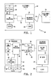
- FIG. 1 is a diagram of one illustrative embodiment of a wireless communication system configured for wireless data and clock communications between two separate electronic devices.
- FIG. 2 is a diagram of one illustrative embodiment of the device function module and the telemetry module of FIG. 1 that further includes a clock and data decoding circuit disposed between the two modules.
- FIG. 3 is a flowchart of one illustrative embodiment of a process for transmitting data from one electronic device in the form of wireless messages containing self-clocking codes to the device function processor of the other electronic device using the clock and data decoding circuit illustrated in FIG. 2 .
- FIG. 4 is a timing diagram illustrating operation of one embodiment of the decoder circuit of FIG. 2 .
- FIG. 5 is a diagram of another illustrative embodiment of the device function module and the telemetry module of FIG. 1 that includes a clock decoding circuit disposed between the two modules.
- FIG. 6 is a diagram of yet another illustrative embodiment of the device function module and the telemetry module of FIG. 1 that includes a single data line connected between the two modules.
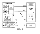
- FIG. 7 is a diagram of a further illustrative embodiment of the device function module and the telemetry module of FIG. 1 that includes a clock line and a data line connected between the two modules.
- FIG. 8 is a diagram of yet another illustrative embodiment of a wireless communication system configured for wireless data and clock communications between two separate electronic devices.
- the electronic device 12 is a medical device and the electronic device 14 is a remote electronic device.
- the medical device 12 may be, for example, an ambulatory medical device, although the medical device 12 may alternatively be or include a non-ambulatory medical device.
- Examples of such an ambulatory medical device may include, but should not be limited to, one or any combination of a medication or drug delivery device such as an infusion pump, a glucose meter, a body fluid analyte sensor system including one or more subcutaneous and/or implanted body fluid analyte sensors, a remote terminal representing a remote infusion pump display on which data from the infusion pump is displayed to a user, or the like.
- a medication or drug delivery device such as an infusion pump, a glucose meter, a body fluid analyte sensor system including one or more subcutaneous and/or implanted body fluid analyte sensors, a remote terminal representing a remote infusion pump display on which data from the infusion pump is displayed to a user, or the like.
- the remote electronic device 14, in this embodiment, may be or include, but should not be limited to, a conventional personal data assistant (PDA) device, an application-specific remote electronic device that may be hand-held, attachable or mountable to clothing, configured to be worn by a person such as on or about a limb or portion thereof, on or about a head or portion thereof, or on or about a body or portion thereof, attachable to a key ring, or the like, a portable wireless communication device with an on-board glucose meter, a smart phone, a personal computer (PC), a laptop, notebook or similar computer, or the like.
- PDA personal data assistant
- an application-specific remote electronic device that may be hand-held, attachable or mountable to clothing, configured to be worn by a person such as on or about a limb or portion thereof, on or about a head or portion thereof, or on or about a body or portion thereof, attachable to a key ring, or the like
- a portable wireless communication device with an on-board glucose meter a smart
- the electronic device 12 is an insulin infusion pump and the remote electronic device 14 is a hand-held smart phone.
- the functionality of the electronic devices 12 and 14 may be reversed, i.e., the electronic device 14 may be a medical device, ambulatory or otherwise, and the electronic device 12 may be a remote electronic device.
- the electronic devices 12 and 14 may both be medical devices, ambulatory or otherwise, and in further embodiments the electronic devices 12 and 14 may both be non-medical electronic devices.
- the electronic device 14 may or may not be configured identically to the electronic device 12, and in any case the electronic devices 12 and 14 are configured to communicate wirelessly with each other via a conventional communication medium 13.
- Examples of the communication medium 13 may include, but should not be limited to, radio frequency (RF), infrared (IR), microwave, inductive coupling, or the like.
- RF radio frequency
- IR infrared
- microwave inductive coupling
- the electronic devices 12 and 14 are each configured to communicate via RF according to a conventional BlueTooth® radio frequency communications protocol.
- the electronic device 12 includes a device function processor 16 that is configured to control all functional operations of the device 12 but not including telemetry operations, i.e., wireless communications with the electronic device 14.
- a clock circuit, 20 is electrically connected to the device function processor 16, and the timing of operation of the device function processor 16 is controlled by the clock circuit 20.
- the electronic device 12 further includes a telemetry processor 18 that is electrically coupled to the device function processor 16.
- the telemetry processor 18 is configured to control wireless communication with the electronic device 14, but not device functions, i.e., non-telemetry operations of the electronic device 12.
- Another clock circuit 22 is electrically connected to the telemetry processor 18, and the timing of operation of the telemetry processor 18 is controlled by the clock circuit 22.
- a clock and data decoding circuit 30 is illustratively connected between the device function processor 16 and the telemetry processor 18.
- the clock and data decoding circuit 30 is shown in FIG. 1 as a dashed line representation to indicate that in some embodiments all of the clock and data decoding circuitry is outside of and between the device function processor 16 and the telemetry processor 18, in other embodiments some or all of the clock and data decoding circuitry 30 may be located in the device function processor 16, and in still other embodiments some or all of the clock and data decoding circuitry 30 may be located in the telemetry processor 18.
- the clock and data decoding circuit 30 is configured to decode and separate clock signals and data signals from wireless messages sent by the electronic device 14 to the electronic device 12 via the communication medium 13, and to use the decoded clock signals to control transfer of the decoded data signals from the telemetry processor 18 to the device function processor 16.
- the electronic device 12 further includes a user interface 24 that is electrically connected to the device function processor 16.
- the user interface 24 illustrated in FIG. 1 illustratively includes a conventional key pad 26 and a conventional display unit 28.
- the device function processor 16 illustratively receives user input via the key pad 26, and provides notifications or messages to the user via the display unit 28.
- the key pad 26 may be or include one or more special purpose keys or buttons, a conventional full-function key board such as those typically found on a personal, laptop or notebook computer, or some number of keys or buttons between one key or button and a full-function key board.
- the display unit 28 may be a conventional liquid crystal display (LCD) unit, or may alternatively be or include a conventional vacuum fluorescent display unit, a conventional light emitting diode (LED) display, one or more conventional light emitting diodes or segments, or the like.
- the user interface 24 may include one or more additional information input devices for providing information from a user or another electronic system to the electronic device 12. Examples of such one or more additional information input devices include, but should not be limited to, a conventional touch-screen display, conventional voice-activated information input circuitry, a conventional wired or wireless data port configured to communicate with an external electronic system or the like.
- the user interface 24 may include one or more other notification or information transfer devices for providing information to a user or other electronic system. Examples of such one or more other notification or information transfer devices include, but should not be limited to, a conventional audio indication device, one or more conventional speakers, a conventional tactile indication device, a conventional wired or wireless data port configured to communicate with an external electronic system or the like.
- the device function processor 16 includes two separate processor circuits.
- a main processor 40 is electrically connected to a non-volatile memory 42, e.g., a conventional FLASH memory, a volatile memory 44, e.g., a random access memory (RAM) and a clock circuit 50.
- the main processor 40 may be, for example, a model V850SA1, 32-bit microcontroller that is commercially available from NEC corporation, although the main processor 40may alternatively be implemented using other conventional microprocessor-based or non-microprocessor-based circuits.
- the device function processor 16 further includes a supervisor processor 46 that is electrically connected to the main processor 40 and also to a clock circuit 48.
- the clock circuits 48 and 50 illustratively comprise the clock circuit 20 illustrated in FIG. 1 .
- the supervisor processor 46 may be, for example, a model PIC12C509, 8-bit microcontroller that is commercially available from Microchip Technology, Inc., although the supervisor processor 46 may alternatively be implemented using other conventional microprocessor-based or non-microprocessor-based circuits.
- the main processor 40 controls the functional operations of the electronic device 12 and the supervisor processor 46 continually monitors the main processor 40 and activates an alarm if the main processor 40 malfunctions.
- the telemetry processor 18 is electrically connected to the clock circuit 22, and includes a conventional base band and logic section 52 and a conventional radio frequency (RF) transceiver circuit 54.
- the telemetry processor 18 includes a main processor and a separate wireless communication processor.
- the wireless communication processor may, for example, be a BlueCore 4-ROM Plug-N-Go, single chip radio and baseband circuit that is commercially available from a number of suppliers such as CSR, and the main processor may be, for example, a model MSP430F2471 16-bit microcontroller as described above.
- the wireless communication processor handles the BlueTooth® communications, i.e., the lower layer of the BlueTooth® protocol stack, and the main processor handles the upper layer of the BlueTooth® protocol stack and, in some embodiments, an additional security layer.
- the main processor and the wireless communication processor may be substituted by a single telemetry processor, e.g., a single BlueCore 4-ROM Plug-N-Go, single chip radio and baseband circuit.
- the electronic device 14 controls all communication on the electronic device 12 between the device function processor 16 and the telemetry processor 18.
- the electronic device 14 generates a clock signal which is passed wirelessly along with data in the form of messages to the electronic device 12 via the wireless communication medium 13.
- the electronic device 12 demodulates the clock signal from the wireless messages, and the clock signal is then employed within the electronic device 12 to control the timing of communication of the data between the device function processor 16 and the telemetry processor 18. All communication between the device function processor 16 and the telemetry processor 18 is thus controlled by messages wirelessly transmitted by the electronic device 14 and received by the electronic device 12.
- the electronic device 14 may send polling requests, interrupts, triggers, synchronization and the like to the device function processor 16 via the telemetry processor 18.
- the device function processor 16 and the telemetry processor 18 operate separately and independently of each other.
- the device function processor 16 controls only the functions and operations of the electronic device 12 that are not telemetry related, and the telemetry processor 18 controls only the telemetry operations. No signals related to polling requests, interrupts, triggers, synchronization or the like are originated by and sent from the device function processor 16 to the telemetry processor 18 or vice versa.
- the device function processor 16 does not control any aspect of when or how the telemetry processor 18 transmits or receives messages or information packets, and the telemetry processor 18 does not control any aspect of when or how the device function processor 16 processes messages or information packets. Any message or information packet that is wirelessly transmitted by the electronic device 14 to the electronic device 12 is forwarded unchanged by the telemetry processor 18 to the device function processor 16.
- the electronic device 14 wirelessly transmits data and clock signals to the electronic device 12 using self-clocking codes.
- self-clocking codes combine data and a clock signal into one signal such that the coded signal can be decoded to determine the data and clock signal without a separate clock or other source of synchronization. This is typically accomplished by including synchronization information within the data portion of the message.
- the clock signal may typically be included as some type of run length limited code (e.g., one that limits the number of back-to-back ones or zeros), and the run length limit is generally selected to limit the run length of ones or zeros in such a way that the receiver of the message can maintain synchronization for the duration of the message. It will be understood, however, that the inclusion of clock signal information in wireless messages transmitted from the electronic device 14 to the electronic device 12 will generally increase the signal bandwidth over messages transmitted without embedded clock signals.
- the clock and data decoding circuit 30' is provided separately from the device function processor 16 and the telemetry processor 18.
- the clock and data decoding circuit 30' includes a conventional phase lock loop (PLL) 56 and a decoder circuit 58 each having an input electrically connected to and receiving information packets from the telemetry processor 18.
- PLL phase lock loop
- the telemetry processor 18 is operable to receive messages wirelessly transmitted by the electronic device 14, and to extract the information packets from the wirelessly received messages by unpacking the information packets from the wireless communication protocol, e.g., from the BlueTooth® communication protocol.
- the information packets include data and clock information in the form of self-clocking codes that are decoded by the PLL 56 and the decoder circuit 58.
- the PLL 58 is operable to extract the clock information from the information packets to produce clock signals, and to provide a PLL clock to the decoder circuit 58 as illustrated in FIG. 2 .
- the decoder circuit 58 is operable to decode the data from the information packets by removing the self-clocking codes embedded in the information packets using the PLL clock.
- Outputs of the PLL 56 and the decoder circuit 58 are electrically connected to the device function processor 16, and the resulting clock signal output of the PLL 56 and the decoded data signal output of the decoder circuit 58 are both provided to the main processor 40 of the device function processor 16.
- the main processor 40 uses the clock signal provided by the PLL 56 to read the data signal provided by the decoder circuit 58.
- the communication between the telemetry processor 18 and the device function processor 16 is thus synchronized by the clock signal generated and provided by the electronic device 14.
- FIG. 3 a flowchart is shown of one illustrative embodiment of a process for transmitting data from the electronic device 14 in the form of wireless messages containing self-clocking codes to the device function processor 16 of the electronic device 12 using the clock and data decoding circuit 30' illustrated in FIG. 2 .
- the flowchart of FIG. 3 is partitioned into the various entities and device/electrical components that carry out the various acts of the clock and data extracting process.
- the device function processor 16 will carry out some of the acts
- the clock and data decoding circuit 30' will carry out some of the acts
- the telemetry processor 18 will carry out some of the acts
- the electronic device 14 will carry out some of the acts.
- the illustrated process begins at step 60 where the electronic device 14 wirelessly transmits a preamble to the telemetry processor 18 of the electronic device 12 via the wireless communication medium 13.
- the telemetry processor 18 is operable to unpack the preamble from the wireless communication protocol structure and to provide the unpacked preamble to the clock and data decoding circuit 30' to wake up the communication channel between the telemetry processor 18 and the device function processor 16 at step 64.
- the information contained in the unpacked preamble locks the PLL 58 such that the PLL runs with the PLL clock operating at a predetermined PLL clock rate or frequency.
- the preamble contains a sequence of ones and zeros that changes state at each bit, e.g., 10101010, although this disclosure contemplates other preamble contents.
- the electronic device 14 then wirelessly transmits a start command with embedded self-clocking codes at step 68 to the telemetry processor 18 of the electronic device 12 via the wireless communication medium 13.
- the telemetry processor 18 is thereafter operable at step 70 to unpack the start command from the wireless communication protocol structure, and to provide the unpacked start command to the clock and data decoding circuit 30'.
- the decoder circuit 58 decodes the unpacked start command by removing the self-clocking codes from the unpacked start command using the PLL clock provided by the PLL 56.
- the resulting decoded start command is sent to the device function processor 16 at step 74. While the decoded start command is being sent to the device function processor 16, the PLL clock is updated at each high to low or low to high transition of the data transmission.
- the device function processor 16 is prepared to receive data until a stop command is received.
- the electronic device 14 After sending the start command, the electronic device 14 is operable to wirelessly transmit a first information packet with embedded self-clocking codes at step 76 1 .
- the telemetry processor 14 is thereafter operable at step 78 1 to unpack the first information packet from the wireless communication protocol structure, and to provide the unpacked first information packet to the clock and data decoding circuit 30'.
- the decoder circuit 58 decodes the unpacked information packet by removing the self-clocking codes from the unpacked first information packet using the PLL clock provided by the PLL 56.
- the resulting decoded first information packet is then sent to the device function processor 16 at step 82 1 .
- the device function processor 16 While the decoded first information packet is being sent to the device function processor 16, operation of the PLL 56 is updated at each high to low or low to high transition of the data transmission, e.g., by updating the PLL clock.
- the device function processor 16 When the decoded information packet is received by the device function processor 16, the device function processor 16 is acts upon the information contained in the first information packet as appropriate. This process is repeated for N information packets as illustrated in FIG. 3 , where N may be any positive integer.
- the electronic device 14 is operable at step 84 to wirelessly transmit a stop command with embedded self-clocking codes to the telemetry processor 18 of the electronic device 12 via the wireless communication medium 13.
- the telemetry processor 18 is thereafter operable at step 86 to unpack the stop command from the wireless communication protocol structure, and to provide the unpacked start command to the clock and data decoding circuit 30'.
- the decoder circuit 58 decodes the unpacked stop command by removing the self-clocking codes from the unpacked stop command using the PLL clock provided by the PLL 56.
- the resulting decoded stop command is sent to the device function processor 16 at step 90. While the decoded stop command is being sent to the device function processor 16, the PLL clock is updated at each high to low or low to high transition of the data transmission.
- the device function processor 16 is informed that no further information packets will follow until another start command is received.
- the PLL 56 thereafter loses its synchronization resulting from the absence of information packets supplied to the clock and data decoding circuit 30' by the telemetry processor 18, the communication channel between the telemetry processor 18 and the device function processor 16 goes back to a sleep state.
- FIG. 4 a timing diagram is shown illustrating operation of one illustrative embodiment of the decoding circuit 58.
- the clock signal exiting the PLL 56 and the data signal exiting the decoder circuit 58 are shown along with one illustrative set of decoding signals.
- the decoding signals are conventional Manchester decoding signals with one being the inverse of the other.
- the Manchester code illustrated in FIG. 4 illustratively encodes a "0" as a low to high transition in the middle of a clock cycle and a "1" as a high to low transition.
- the Manchester code is accordingly well suited for the illustrated communication scheme as each bit as a resynchronization transition.
- FIG. 5 another illustrative embodiment of the device function processor 16, the telemetry processor 18 and the clock and data decoding circuit 30" respectively is shown.
- the device function processor 16 and the telemetry processor 18 are identical to the device function processor 16 and the telemetry processor 18 illustrated and describe hereinabove with respect to FIG. 2 .
- Like numbers are therefore used in FIG. 5 to identify like components.
- the clock and data decoding circuit 30" differs from the clock and data decoding circuit 30' of FIG. 2 in that the portion of the clock and data decoding circuit 30" that is separate from and connected between the device function processor 16 and the telemetry processor 18 includes only the PLL 56.
- the decoding circuit 58 is included in the main processor 54 of the device function processor 16 in the form of instructions that are stored in the memory 42 and that are executable by the main processor 40 to decode the data from the wirelessly received information at a decode rate defined by the clock signal produced by the PLL circuit 56.
- a decoding scheme other than the Manchester decoding scheme is used to directly convert bit codes into commands or data.
- decoding schemes based on x-to-y coding e.g., 4B5B or 8B10B, may be used.
- FIG. 6 yet another illustrative embodiment of the device function processor 16, the telemetry processor 18 and the clock and data decoding circuit 30'" respectively is shown.
- the device function processor 16 and the telemetry processor 18 are identical to the device function processor 16 and the telemetry processor 18 illustrated and describe hereinabove with respect to FIG. 2 .
- Like numbers are therefore used in FIG. 5 to identify like components.
- the clock and data decoding circuit 30'" differs from the clock and data decoding circuits 30' of FIG. 2 and 30" of FIG.
- the entirety of the clocking and data decoding circuit 30'" is, in this embodiment, included in the main processor 54 of the device function processor 16 in the form of instructions that are stored in the memory 42 and that are executable by the main processor 40 to carry out the entirety of the operation of the clock and data decoding circuit 30' as described with respect to FIGS. 2-4 .
- the instructions stored in the memory 42 are executable by the main processor 40 to extract the clock information from the wirelessly received information to produce the clock signal that was produced in the previous embodiments by the PLL 56, and to decode the data from the wirelessly received information at a decode rate defined by the clock signal.
- the task of the telemetry processor 18, in this embodiment, is thus to receive messages wirelessly transmitted by the electronic device 14, to unpack the messages from the wireless communication protocol structure, and to send the unpacked messages in their entirety to the device function processor 16.
- the PLL implementation in the main processor 54 is illustratively accomplished using software that is based on interrupts and internal timers of the main processor 54.
- a decoding scheme other than the Manchester decoding scheme is illustratively used in this embodiment to directly convert bit codes into commands or data in the main processor 54.
- decoding schemes based on x-to-y coding e.g., 4B5B or 8B10B, may illustratively be used.
- the electronic device 14 wirelessly transmits data and clock signals to the electronic device 12 using two separate channels; one that transmits clock information and another that transmits data.
- the telemetry processor 18 in this embodiment is accordingly configured to process and decode the two incoming channels into two synchronous output channels; one that contains data extracted by the telemetry processor 18 from one of the two incoming channels and the other that contains a clock signal extracted by the telemetry processor 18 from the clock information in the other incoming channel.
- One of the synchronous output channels carries the decoded or extracted clock signal to the device function processor 16, and the other synchronous output channel carries the decoded data signal to the device function processor 16.
- information may be wirelessly transferred between the electronic device 12 and the electronic device 14 in the form of information packets or on a dedicated audio format (e.g., pulse code modulated) via a synchronous connection-oriented link (SCO) or an asynchronous connectionless link (ACL).
- clock and data decoding circuit 30"' in this embodiment includes a microcontroller connected to the BlueTooth® processor to extract bit streams of data from the information packets in the data channel. The audio channel may then be used to transmit a modulated audio signal, e.g., via phase or frequency modulation, to be used as the clock signal.
- a conventional transceiver may be included in the telemetry processor 18 to implement a radio frequency (RF) link which directly outputs received data bits on a dedicated pin.
- the transceiver may be, for example, a nRF2401 A transceiver that is commercially available from Nordic Semiconductor, although other transceiver circuits may alternatively be used.
- the RF link does not follow the BlueTooth® standard, however, and therefore does not support two simultaneous communication channels. Additional circuitry is thus required to convert the audio signal into a suitable clock signal.
- Those skilled in the art will be aware of conventional circuitry that can be used to convert the audio signal into a suitable clock signal and to synchronize the clock signal with the data bits on the RF link.
- the wireless communication system 100 illustrated in FIG.8 is configured for wireless communications between two separate electronic devices 12 and 14'.
- the electronic device 12 is a medical device and the electronic device 14' is a remote electronic device, although the electronic device 12 may alternatively be a wireless communication device and the electronic device 14' may be a medical device or the electronic devices 12 and 14' may both be medical devices or wireless communication devices.
- the electronic device 12 may be identical to the electronic device 12 illustrated and described with respect to FIG. 1 , with the exception that the device function processor 16 is directly connected to the telemetry processor 18, and in this embodiment the device function processor 16 may provide information to the telemetry system 18 for wireless transmission to the electronic device 14'. It will be understood, however, that apart from the processors 16, 18 and the clock and data decoding circuit 30 the electronic device 12 may alternatively include more or fewer electronic components than that illustrated and describe with respect to FIG. 1 .
- the electronic device 14' illustratively contains the same elements as the electronic device 12 with the same functions as the electronic device 12.
- the electronic device 14' illustratively includes a device function processor 116 that is configured to control all functional operations of the device 14' but not including telemetry operations, i.e., wireless communications with the electronic device 12, a clock circuit, 120 electrically connected to the device function processor 116, wherein the timing of operation of the device function processor 116 is controlled by the clock circuit 120.
- the electronic device 14' further includes a telemetry processor 118 that is electrically coupled to the device function processor 116 via a clock and data decoding circuit 130 and also via direct electrical connection.
- the telemetry processor 118 is configured to control wireless communication with the electronic device 12, but not device functions, i.e., non-telemetry operations of the electronic device 14'.
- the electronic device 14' may further includes a user interface 124 that may include a keypad 126 and/or a display device 128 as illustrated and described with respect to FIG. 1 .
- FIG. 8 is not limited to two identical electronic devices. It should also be understood that the two clock and data decoding circuits 30 and 130 need not be implemented identically, and either of the clock and data decoding circuits 30 and 130 may be implemented accordingly to any of the previous embodiments illustrated and described with respect to FIGS. 2-7 .
- the electronic devices 12 and 14' are each configured for two-way communications.
- the direct connection between the device function processor 16, 160 and the telemetry processor 30, 130 is used for transmitting data from the device function processor 16, 116 to the other device function processor 116, 16 in the form of wireless messages containing self-clocking codes.
- the communication system 100 allows for bi-directional communication between the electronic device 12 and the electronic device 14'.
Landscapes
- Engineering & Computer Science (AREA)
- Health & Medical Sciences (AREA)
- Biomedical Technology (AREA)
- Medical Informatics (AREA)
- Signal Processing (AREA)
- Business, Economics & Management (AREA)
- General Business, Economics & Management (AREA)
- Epidemiology (AREA)
- General Health & Medical Sciences (AREA)
- Computer Networks & Wireless Communication (AREA)
- Primary Health Care (AREA)
- Public Health (AREA)
- Mobile Radio Communication Systems (AREA)
- Selective Calling Equipment (AREA)
Applications Claiming Priority (1)
| Application Number | Priority Date | Filing Date | Title |
|---|---|---|---|
| US12/134,944 US8132037B2 (en) | 2008-06-06 | 2008-06-06 | Apparatus and method for processing wirelessly communicated data and clock information within an electronic device |
Publications (1)
| Publication Number | Publication Date |
|---|---|
| EP2131503A1 true EP2131503A1 (de) | 2009-12-09 |
Family
ID=41066025
Family Applications (1)
| Application Number | Title | Priority Date | Filing Date |
|---|---|---|---|
| EP09160345A Ceased EP2131503A1 (de) | 2008-06-06 | 2009-05-15 | Vorrichtung und Verfahren zur Verarbeitung von drahtlos kommunizierten Daten und Uhrinformation in einer elektronischen Vorrichtung |
Country Status (2)
| Country | Link |
|---|---|
| US (2) | US8132037B2 (de) |
| EP (1) | EP2131503A1 (de) |
Families Citing this family (115)
| Publication number | Priority date | Publication date | Assignee | Title |
|---|---|---|---|---|
| US8771183B2 (en) | 2004-02-17 | 2014-07-08 | Abbott Diabetes Care Inc. | Method and system for providing data communication in continuous glucose monitoring and management system |
| AU2003303597A1 (en) | 2002-12-31 | 2004-07-29 | Therasense, Inc. | Continuous glucose monitoring system and methods of use |
| US7587287B2 (en) * | 2003-04-04 | 2009-09-08 | Abbott Diabetes Care Inc. | Method and system for transferring analyte test data |
| US7679407B2 (en) * | 2003-04-28 | 2010-03-16 | Abbott Diabetes Care Inc. | Method and apparatus for providing peak detection circuitry for data communication systems |
| US7722536B2 (en) * | 2003-07-15 | 2010-05-25 | Abbott Diabetes Care Inc. | Glucose measuring device integrated into a holster for a personal area network device |
| CA3110101A1 (en) | 2004-06-04 | 2005-12-15 | Abbott Diabetes Care Inc. | Systems and methods for managing diabetes care data |
| US9351669B2 (en) | 2009-09-30 | 2016-05-31 | Abbott Diabetes Care Inc. | Interconnect for on-body analyte monitoring device |
| US9788771B2 (en) | 2006-10-23 | 2017-10-17 | Abbott Diabetes Care Inc. | Variable speed sensor insertion devices and methods of use |
| US8029441B2 (en) | 2006-02-28 | 2011-10-04 | Abbott Diabetes Care Inc. | Analyte sensor transmitter unit configuration for a data monitoring and management system |
| US7545272B2 (en) | 2005-02-08 | 2009-06-09 | Therasense, Inc. | RF tag on test strips, test strip vials and boxes |
| US7768408B2 (en) | 2005-05-17 | 2010-08-03 | Abbott Diabetes Care Inc. | Method and system for providing data management in data monitoring system |
| US7583190B2 (en) * | 2005-10-31 | 2009-09-01 | Abbott Diabetes Care Inc. | Method and apparatus for providing data communication in data monitoring and management systems |
| US8219173B2 (en) | 2008-09-30 | 2012-07-10 | Abbott Diabetes Care Inc. | Optimizing analyte sensor calibration |
| US9675290B2 (en) | 2012-10-30 | 2017-06-13 | Abbott Diabetes Care Inc. | Sensitivity calibration of in vivo sensors used to measure analyte concentration |
| US7620438B2 (en) | 2006-03-31 | 2009-11-17 | Abbott Diabetes Care Inc. | Method and system for powering an electronic device |
| US8478557B2 (en) | 2009-07-31 | 2013-07-02 | Abbott Diabetes Care Inc. | Method and apparatus for providing analyte monitoring system calibration accuracy |
| US7801582B2 (en) | 2006-03-31 | 2010-09-21 | Abbott Diabetes Care Inc. | Analyte monitoring and management system and methods therefor |
| US20080199894A1 (en) | 2007-02-15 | 2008-08-21 | Abbott Diabetes Care, Inc. | Device and method for automatic data acquisition and/or detection |
| US8123686B2 (en) | 2007-03-01 | 2012-02-28 | Abbott Diabetes Care Inc. | Method and apparatus for providing rolling data in communication systems |
| US10111608B2 (en) | 2007-04-14 | 2018-10-30 | Abbott Diabetes Care Inc. | Method and apparatus for providing data processing and control in medical communication system |
| CA2683962C (en) | 2007-04-14 | 2017-06-06 | Abbott Diabetes Care Inc. | Method and apparatus for providing data processing and control in medical communication system |
| US9615780B2 (en) | 2007-04-14 | 2017-04-11 | Abbott Diabetes Care Inc. | Method and apparatus for providing data processing and control in medical communication system |
| ES2461090T3 (es) | 2007-04-14 | 2014-05-16 | Abbott Diabetes Care Inc. | Procedimiento y aparato para proporcionar tratamiento y control de datos en un sistema de comunicación médica |
| US8461985B2 (en) | 2007-05-08 | 2013-06-11 | Abbott Diabetes Care Inc. | Analyte monitoring system and methods |
| US7928850B2 (en) | 2007-05-08 | 2011-04-19 | Abbott Diabetes Care Inc. | Analyte monitoring system and methods |
| US8665091B2 (en) | 2007-05-08 | 2014-03-04 | Abbott Diabetes Care Inc. | Method and device for determining elapsed sensor life |
| US8456301B2 (en) | 2007-05-08 | 2013-06-04 | Abbott Diabetes Care Inc. | Analyte monitoring system and methods |
| US8239166B2 (en) | 2007-05-14 | 2012-08-07 | Abbott Diabetes Care Inc. | Method and apparatus for providing data processing and control in a medical communication system |
| US10002233B2 (en) | 2007-05-14 | 2018-06-19 | Abbott Diabetes Care Inc. | Method and apparatus for providing data processing and control in a medical communication system |
| US8103471B2 (en) | 2007-05-14 | 2012-01-24 | Abbott Diabetes Care Inc. | Method and apparatus for providing data processing and control in a medical communication system |
| US8260558B2 (en) | 2007-05-14 | 2012-09-04 | Abbott Diabetes Care Inc. | Method and apparatus for providing data processing and control in a medical communication system |
| US8600681B2 (en) | 2007-05-14 | 2013-12-03 | Abbott Diabetes Care Inc. | Method and apparatus for providing data processing and control in a medical communication system |
| US8444560B2 (en) | 2007-05-14 | 2013-05-21 | Abbott Diabetes Care Inc. | Method and apparatus for providing data processing and control in a medical communication system |
| US8560038B2 (en) | 2007-05-14 | 2013-10-15 | Abbott Diabetes Care Inc. | Method and apparatus for providing data processing and control in a medical communication system |
| US9125548B2 (en) | 2007-05-14 | 2015-09-08 | Abbott Diabetes Care Inc. | Method and apparatus for providing data processing and control in a medical communication system |
| US8026382B2 (en) * | 2007-05-18 | 2011-09-27 | Heidi Kay | Lipid raft, caveolin protein, and caveolar function modulation compounds and associated synthetic and therapeutic methods |
| US8597188B2 (en) | 2007-06-21 | 2013-12-03 | Abbott Diabetes Care Inc. | Health management devices and methods |
| WO2008157821A1 (en) * | 2007-06-21 | 2008-12-24 | Abbott Diabetes Care, Inc. | Health monitor |
| US8160900B2 (en) | 2007-06-29 | 2012-04-17 | Abbott Diabetes Care Inc. | Analyte monitoring and management device and method to analyze the frequency of user interaction with the device |
| US8834366B2 (en) | 2007-07-31 | 2014-09-16 | Abbott Diabetes Care Inc. | Method and apparatus for providing analyte sensor calibration |
| US7826382B2 (en) | 2008-05-30 | 2010-11-02 | Abbott Diabetes Care Inc. | Close proximity communication device and methods |
| US9402544B2 (en) | 2009-02-03 | 2016-08-02 | Abbott Diabetes Care Inc. | Analyte sensor and apparatus for insertion of the sensor |
| US9226701B2 (en) | 2009-04-28 | 2016-01-05 | Abbott Diabetes Care Inc. | Error detection in critical repeating data in a wireless sensor system |
| US8368556B2 (en) | 2009-04-29 | 2013-02-05 | Abbott Diabetes Care Inc. | Method and system for providing data communication in continuous glucose monitoring and management system |
| WO2010138856A1 (en) | 2009-05-29 | 2010-12-02 | Abbott Diabetes Care Inc. | Medical device antenna systems having external antenna configurations |
| EP2473099A4 (de) | 2009-08-31 | 2015-01-14 | Abbott Diabetes Care Inc | Analytüberwachungssystem und -verfahren zur leistungs- und rauschverwaltung |
| WO2011025549A1 (en) | 2009-08-31 | 2011-03-03 | Abbott Diabetes Care Inc. | Medical devices and methods |
| US8521101B1 (en) | 2009-09-17 | 2013-08-27 | Rf Micro Devices, Inc. | Extracting clock information from a serial communications bus for use in RF communications circuitry |
| US20110184268A1 (en) * | 2010-01-22 | 2011-07-28 | Abbott Diabetes Care Inc. | Method, Device and System for Providing Analyte Sensor Calibration |
| CA2766685A1 (en) | 2010-03-24 | 2011-12-29 | Abbott Diabetes Care Inc. | Medical device inserters and processes of inserting and using medical devices |
| US20110248755A1 (en) * | 2010-04-08 | 2011-10-13 | Hasenplaugh William C | Cross-feedback phase-locked loop for distributed clocking systems |
| KR101208894B1 (ko) * | 2010-05-24 | 2012-12-06 | 주식회사 엠아이텍 | 생체이식형 의료기기의 데이터 송수신 장치 및 방법 |
| US8635046B2 (en) | 2010-06-23 | 2014-01-21 | Abbott Diabetes Care Inc. | Method and system for evaluating analyte sensor response characteristics |
| US9241635B2 (en) | 2010-09-30 | 2016-01-26 | Fitbit, Inc. | Portable monitoring devices for processing applications and processing analysis of physiological conditions of a user associated with the portable monitoring device |
| US9253168B2 (en) | 2012-04-26 | 2016-02-02 | Fitbit, Inc. | Secure pairing of devices via pairing facilitator-intermediary device |
| US8805646B2 (en) | 2010-09-30 | 2014-08-12 | Fitbit, Inc. | Methods, systems and devices for linking user devices to activity tracking devices |
| US8954290B2 (en) | 2010-09-30 | 2015-02-10 | Fitbit, Inc. | Motion-activated display of messages on an activity monitoring device |
| US9310909B2 (en) | 2010-09-30 | 2016-04-12 | Fitbit, Inc. | Methods, systems and devices for physical contact activated display and navigation |
| US11243093B2 (en) | 2010-09-30 | 2022-02-08 | Fitbit, Inc. | Methods, systems and devices for generating real-time activity data updates to display devices |
| US8712724B2 (en) | 2010-09-30 | 2014-04-29 | Fitbit, Inc. | Calendar integration methods and systems for presentation of events having combined activity and location information |
| US10004406B2 (en) | 2010-09-30 | 2018-06-26 | Fitbit, Inc. | Portable monitoring devices for processing applications and processing analysis of physiological conditions of a user associated with the portable monitoring device |
| US8954291B2 (en) | 2010-09-30 | 2015-02-10 | Fitbit, Inc. | Alarm setting and interfacing with gesture contact interfacing controls |
| US8762101B2 (en) | 2010-09-30 | 2014-06-24 | Fitbit, Inc. | Methods and systems for identification of event data having combined activity and location information of portable monitoring devices |
| US8694282B2 (en) | 2010-09-30 | 2014-04-08 | Fitbit, Inc. | Methods and systems for geo-location optimized tracking and updating for events having combined activity and location information |
| US9390427B2 (en) | 2010-09-30 | 2016-07-12 | Fitbit, Inc. | Methods, systems and devices for automatic linking of activity tracking devices to user devices |
| US8738321B2 (en) | 2010-09-30 | 2014-05-27 | Fitbit, Inc. | Methods and systems for classification of geographic locations for tracked activity |
| US8620617B2 (en) | 2010-09-30 | 2013-12-31 | Fitbit, Inc. | Methods and systems for interactive goal setting and recommender using events having combined activity and location information |
| US9148483B1 (en) | 2010-09-30 | 2015-09-29 | Fitbit, Inc. | Tracking user physical activity with multiple devices |
| US8762102B2 (en) | 2010-09-30 | 2014-06-24 | Fitbit, Inc. | Methods and systems for generation and rendering interactive events having combined activity and location information |
| US10983945B2 (en) | 2010-09-30 | 2021-04-20 | Fitbit, Inc. | Method of data synthesis |
| US8615377B1 (en) | 2010-09-30 | 2013-12-24 | Fitbit, Inc. | Methods and systems for processing social interactive data and sharing of tracked activity associated with locations |
| US8744803B2 (en) * | 2010-09-30 | 2014-06-03 | Fitbit, Inc. | Methods, systems and devices for activity tracking device data synchronization with computing devices |
| US8738323B2 (en) | 2010-09-30 | 2014-05-27 | Fitbit, Inc. | Methods and systems for metrics analysis and interactive rendering, including events having combined activity and location information |
| EP2624745A4 (de) | 2010-10-07 | 2018-05-23 | Abbott Diabetes Care, Inc. | Analytüberwachungsvorrichtungen und -verfahren |
| US8488732B2 (en) * | 2011-01-05 | 2013-07-16 | Himax Media Solutions, Inc. | Communication receiver and a receiving method |
| US10136845B2 (en) | 2011-02-28 | 2018-11-27 | Abbott Diabetes Care Inc. | Devices, systems, and methods associated with analyte monitoring devices and devices incorporating the same |
| CA3115682C (en) | 2011-02-28 | 2025-10-07 | Abbott Diabetes Care Inc. | DEVICES, SYSTEMS AND METHODS ASSOCIATED WITH ANALYTE MONITORING DEVICES, AND DEVICES COMPRISING SAID ANALYTE MONITORING DEVICES |
| US8738925B1 (en) | 2013-01-07 | 2014-05-27 | Fitbit, Inc. | Wireless portable biometric device syncing |
| US9974472B2 (en) | 2011-06-16 | 2018-05-22 | Abbott Diabetes Care Inc. | Temperature-compensated analyte monitoring devices, systems, and methods thereof |
| WO2013066849A1 (en) | 2011-10-31 | 2013-05-10 | Abbott Diabetes Care Inc. | Model based variable risk false glucose threshold alarm prevention mechanism |
| US9069536B2 (en) | 2011-10-31 | 2015-06-30 | Abbott Diabetes Care Inc. | Electronic devices having integrated reset systems and methods thereof |
| EP2775918B1 (de) | 2011-11-07 | 2020-02-12 | Abbott Diabetes Care Inc. | Analytüberwachungsvorrichtung und -verfahren |
| US9317656B2 (en) | 2011-11-23 | 2016-04-19 | Abbott Diabetes Care Inc. | Compatibility mechanisms for devices in a continuous analyte monitoring system and methods thereof |
| US8710993B2 (en) | 2011-11-23 | 2014-04-29 | Abbott Diabetes Care Inc. | Mitigating single point failure of devices in an analyte monitoring system and methods thereof |
| WO2013090215A2 (en) | 2011-12-11 | 2013-06-20 | Abbot Diabetes Care Inc. | Analyte sensor devices, connections, and methods |
| US9641239B2 (en) | 2012-06-22 | 2017-05-02 | Fitbit, Inc. | Adaptive data transfer using bluetooth |
| EP2890297B1 (de) | 2012-08-30 | 2018-04-11 | Abbott Diabetes Care, Inc. | Ausfallerkennung bei kontinuierlichen analytüberwachungsdaten bei datenabweichungen |
| US9968306B2 (en) | 2012-09-17 | 2018-05-15 | Abbott Diabetes Care Inc. | Methods and apparatuses for providing adverse condition notification with enhanced wireless communication range in analyte monitoring systems |
| US9907492B2 (en) | 2012-09-26 | 2018-03-06 | Abbott Diabetes Care Inc. | Method and apparatus for improving lag correction during in vivo measurement of analyte concentration with analyte concentration variability and range data |
| US8982999B2 (en) * | 2012-09-30 | 2015-03-17 | Intel Corporation | Jitter tolerant receiver |
| US9728059B2 (en) | 2013-01-15 | 2017-08-08 | Fitbit, Inc. | Sedentary period detection utilizing a wearable electronic device |
| US9039614B2 (en) | 2013-01-15 | 2015-05-26 | Fitbit, Inc. | Methods, systems and devices for measuring fingertip heart rate |
| US8738101B1 (en) * | 2013-02-06 | 2014-05-27 | Makor Issues And Rights Ltd. | Smartphone-tablet hybrid device |
| US10076285B2 (en) | 2013-03-15 | 2018-09-18 | Abbott Diabetes Care Inc. | Sensor fault detection using analyte sensor data pattern comparison |
| US10433773B1 (en) | 2013-03-15 | 2019-10-08 | Abbott Diabetes Care Inc. | Noise rejection methods and apparatus for sparsely sampled analyte sensor data |
| US9474475B1 (en) | 2013-03-15 | 2016-10-25 | Abbott Diabetes Care Inc. | Multi-rate analyte sensor data collection with sample rate configurable signal processing |
| US9031812B2 (en) | 2014-02-27 | 2015-05-12 | Fitbit, Inc. | Notifications on a user device based on activity detected by an activity monitoring device |
| US11990019B2 (en) | 2014-02-27 | 2024-05-21 | Fitbit, Inc. | Notifications on a user device based on activity detected by an activity monitoring device |
| WO2015153482A1 (en) | 2014-03-30 | 2015-10-08 | Abbott Diabetes Care Inc. | Method and apparatus for determining meal start and peak events in analyte monitoring systems |
| US9344546B2 (en) | 2014-05-06 | 2016-05-17 | Fitbit, Inc. | Fitness activity related messaging |
| AU2016260547B2 (en) | 2015-05-14 | 2020-09-03 | Abbott Diabetes Care Inc. | Compact medical device inserters and related systems and methods |
| US10213139B2 (en) | 2015-05-14 | 2019-02-26 | Abbott Diabetes Care Inc. | Systems, devices, and methods for assembling an applicator and sensor control device |
| EP3319518B1 (de) | 2015-07-10 | 2025-08-13 | Abbott Diabetes Care Inc. | System und vorrichtung zur dynamischen glukoseprofilreaktion auf physiologische parameter |
| US10080530B2 (en) | 2016-02-19 | 2018-09-25 | Fitbit, Inc. | Periodic inactivity alerts and achievement messages |
| EP4277322A3 (de) | 2016-07-20 | 2024-01-24 | Dexcom, Inc. | System und verfahren zur drahtlosen kommunikation von glucosedaten |
| US11019411B2 (en) * | 2016-10-18 | 2021-05-25 | Dexcom, Inc. | System and method for communication of analyte data |
| US11032855B2 (en) | 2016-10-18 | 2021-06-08 | Dexcom, Inc. | System and method for communication of analyte data |
| KR102576707B1 (ko) * | 2016-12-26 | 2023-09-08 | 삼성전자주식회사 | 전자 시스템 및 그 동작 방법 |
| CN115444410B (zh) | 2017-01-23 | 2025-08-15 | 雅培糖尿病护理公司 | 用于插入体内分析物传感器的施加器及组件 |
| EP4621804A3 (de) | 2017-03-21 | 2025-12-10 | Abbott Diabetes Care, Inc. | Verfahren, vorrichtungen und system zur bereitstellung von diagnose und therapie von diabetischen zuständen |
| US10705557B2 (en) * | 2018-03-30 | 2020-07-07 | Qualcomm Incorporated | On-chip clock generator calibration |
| WO2020131159A1 (en) | 2018-12-21 | 2020-06-25 | Abbott Diabetes Care Inc. | Systems, devices, and methods for analyte sensor insertion |
| CN115942909A (zh) | 2020-08-31 | 2023-04-07 | 雅培糖尿病护理公司 | 用于分析物传感器插入的系统、装置和方法 |
| ES3000715T3 (en) | 2020-09-15 | 2025-03-03 | Abbott Diabetes Care Inc | Device for analyte monitoring |
| MY202051A (en) | 2021-07-16 | 2024-03-30 | Abbott Diabetes Care Inc | Systems, devices, and methods for analyte monitoring |
Citations (5)
| Publication number | Priority date | Publication date | Assignee | Title |
|---|---|---|---|---|
| EP1164759A2 (de) * | 2000-06-12 | 2001-12-19 | Broadcom Corporation | Spiegelfrequenzunterdrückung in Quadraturdemodulatoren |
| EP1164692A2 (de) * | 2000-06-12 | 2001-12-19 | Broadcom Corporation | Empfängerstruktur mit niedriger Zwischenfrequenz und Mehrphasenfiltern |
| EP1335532A2 (de) * | 2002-02-12 | 2003-08-13 | Broadcom Corporation | Digital-/Analogkonverter mit Zeit-Dithering zum Ausblenden von Audiotönen |
| US20060198364A1 (en) * | 2005-03-07 | 2006-09-07 | Kunihide Fujii | Communication system, communication device, wired communication device, and communication method |
| US20070202827A1 (en) | 2000-06-12 | 2007-08-30 | Sherman Lee | Wireless data communications using FIFO for synchronization memory |
Family Cites Families (51)
| Publication number | Priority date | Publication date | Assignee | Title |
|---|---|---|---|---|
| US3654492A (en) * | 1970-08-24 | 1972-04-04 | Itt | Code communication frame synchronization system |
| US4493021A (en) * | 1981-04-03 | 1985-01-08 | The United States Of America As Represented By The Administrator Of The National Aeronautics And Space Administration | Multicomputer communication system |
| US5536249A (en) | 1994-03-09 | 1996-07-16 | Visionary Medical Products, Inc. | Pen-type injector with a microprocessor and blood characteristic monitor |
| US5582593A (en) | 1994-07-21 | 1996-12-10 | Hultman; Barry W. | Ambulatory medication delivery system |
| US5665065A (en) | 1995-05-26 | 1997-09-09 | Minimed Inc. | Medication infusion device with blood glucose data input |
| US5726650A (en) * | 1995-06-07 | 1998-03-10 | Silicon Systems, Inc. | Adaptive manchester decoding with adjustable delay and power saving mode |
| JP2831324B2 (ja) | 1996-03-28 | 1998-12-02 | アンリツ株式会社 | 無線機試験装置 |
| US6554798B1 (en) | 1998-08-18 | 2003-04-29 | Medtronic Minimed, Inc. | External infusion device with remote programming, bolus estimator and/or vibration alarm capabilities |
| US6540672B1 (en) | 1998-12-09 | 2003-04-01 | Novo Nordisk A/S | Medical system and a method of controlling the system for use by a patient for medical self treatment |
| ATE336198T1 (de) | 1998-11-30 | 2006-09-15 | Novo Nordisk As | Medizinische vorrichtung und verfahren der kontrolle der vorrichtung welche von einem patienten zur selbstbehandlung verwendet wird |
| US7369635B2 (en) | 2000-01-21 | 2008-05-06 | Medtronic Minimed, Inc. | Rapid discrimination preambles and methods for using the same |
| US6813519B2 (en) | 2000-01-21 | 2004-11-02 | Medtronic Minimed, Inc. | Ambulatory medical apparatus and method using a robust communication protocol |
| US6738670B1 (en) | 2000-06-19 | 2004-05-18 | Medtronic, Inc. | Implantable medical device telemetry processor |
| US6650951B1 (en) | 2000-06-19 | 2003-11-18 | International Business Machines Corporation | Method and insulin pump for providing a forgotten bolus warning |
| US20040260233A1 (en) | 2000-09-08 | 2004-12-23 | Garibotto John T. | Data collection assembly for patient infusion system |
| JP2004524869A (ja) | 2000-10-04 | 2004-08-19 | インシュレット コーポレイション | 患者の輸液システム用のデータ収集アセンブリ |
| US6634014B1 (en) | 2000-12-12 | 2003-10-14 | Lsi Logic Corporation | Delay/load estimation for use in integrated circuit design |
| JP2004532664A (ja) | 2000-12-21 | 2004-10-28 | インシュレット コーポレイション | 医療機器の遠隔制御装置及び方法 |
| IL152098A0 (en) | 2001-02-08 | 2003-07-31 | Inverness Medical Ltd | A personal conditional management system |
| DE60142801D1 (de) * | 2001-06-15 | 2010-09-23 | St Microelectronics Sa | Integrierte schaltung mit niedriger leistung und mit eindraht kommunikationsinterface |
| US7179226B2 (en) | 2001-06-21 | 2007-02-20 | Animas Corporation | System and method for managing diabetes |
| US20030009341A1 (en) | 2001-07-05 | 2003-01-09 | Tien-Yao Cheng | Humanistic devices and methods for same |
| WO2003009207A1 (en) | 2001-07-20 | 2003-01-30 | Medical Research Group | Ambulatory medical apparatus and method using a robust communication protocol |
| WO2003009208A1 (en) | 2001-07-20 | 2003-01-30 | Medical Research Group | Method and apparatus for communicating between an ambulatory medical device and a control device via telemetry using randomized data |
| ATE454846T1 (de) | 2001-08-13 | 2010-01-15 | Novo Nordisk As | System zur steuerung von drahtlosen dateninformationen zwischen zwei tragbaren medizinischen vorrichtungen und zur informationsübertragung an einen dritten teilnehmer |
| US20030065536A1 (en) | 2001-08-13 | 2003-04-03 | Hansen Henrik Egesborg | Portable device and method of communicating medical data information |
| JP3687599B2 (ja) * | 2001-12-06 | 2005-08-24 | ソニー株式会社 | 通信装置および方法、記録媒体、並びにプログラム |
| US7204823B2 (en) | 2001-12-19 | 2007-04-17 | Medtronic Minimed, Inc. | Medication delivery system and monitor |
| US6744350B2 (en) | 2002-02-28 | 2004-06-01 | Smiths Medical Md, Inc. | Insulin pump having missed meal bolus alarm |
| US8504179B2 (en) | 2002-02-28 | 2013-08-06 | Smiths Medical Asd, Inc. | Programmable medical infusion pump |
| GB2389419B (en) | 2002-06-05 | 2006-02-22 | Diabetes Diagnostics Inc | Analyte testing device |
| US20040068230A1 (en) | 2002-07-24 | 2004-04-08 | Medtronic Minimed, Inc. | System for providing blood glucose measurements to an infusion device |
| US8512276B2 (en) | 2002-07-24 | 2013-08-20 | Medtronic Minimed, Inc. | System for providing blood glucose measurements to an infusion device |
| US7278983B2 (en) | 2002-07-24 | 2007-10-09 | Medtronic Minimed, Inc. | Physiological monitoring device for controlling a medication infusion device |
| JP2007525241A (ja) | 2003-04-18 | 2007-09-06 | インシュレット コーポレイション | 注入ポンプ用リモコンのためのユーザーインターフェース及びそれの使用方法 |
| US20050090808A1 (en) | 2003-04-30 | 2005-04-28 | Luis Malave | Multi-processor medical device |
| US7936830B2 (en) * | 2003-05-29 | 2011-05-03 | Maxim Integrated Products, Inc. | Active rectifier with load impedance switching |
| US8066639B2 (en) | 2003-06-10 | 2011-11-29 | Abbott Diabetes Care Inc. | Glucose measuring device for use in personal area network |
| US8071028B2 (en) | 2003-06-12 | 2011-12-06 | Abbott Diabetes Care Inc. | Method and apparatus for providing power management in data communication systems |
| JP3916591B2 (ja) * | 2003-06-16 | 2007-05-16 | アンリツ株式会社 | 試験装置 |
| US7529565B2 (en) * | 2004-04-08 | 2009-05-05 | Starkey Laboratories, Inc. | Wireless communication protocol |
| US8095123B2 (en) * | 2005-06-13 | 2012-01-10 | Roche Diagnostics International Ag | Wireless communication system |
| US8249209B2 (en) * | 2005-06-20 | 2012-08-21 | Bloomberg Finance L.P. | Synchronous one-bit interface protocol or data structure |
| US20070060869A1 (en) | 2005-08-16 | 2007-03-15 | Tolle Mike C V | Controller device for an infusion pump |
| US20070060870A1 (en) | 2005-08-16 | 2007-03-15 | Tolle Mike Charles V | Controller device for an infusion pump |
| US7713240B2 (en) | 2005-09-13 | 2010-05-11 | Medtronic Minimed, Inc. | Modular external infusion device |
| US8102789B2 (en) | 2005-12-29 | 2012-01-24 | Medtronic, Inc. | System and method for synchronous wireless communication with a medical device |
| CN101207472B (zh) * | 2006-12-20 | 2012-03-14 | 国际商业机器公司 | 同步时钟信道和数据信道信号的通信系统及接收器和方法 |
| EP2132678B2 (de) | 2007-02-05 | 2018-04-04 | Medtronic MiniMed, Inc. | Drahtlose datenübertragungsprotokolle und -verfahren für ein drahtloses medizinisches gerätenetzwerk |
| GB2446622A (en) * | 2007-02-14 | 2008-08-20 | Sharp Kk | Wireless interface |
| FR2914807B1 (fr) * | 2007-04-06 | 2012-11-16 | Centre Nat Detudes Spatiales Cnes | Dispositif d'extraction d'horloge a asservissement numerique de phase sans reglage externe |
-
2008
- 2008-06-06 US US12/134,944 patent/US8132037B2/en active Active
-
2009
- 2009-05-15 EP EP09160345A patent/EP2131503A1/de not_active Ceased
-
2012
- 2012-02-02 US US13/364,546 patent/US8738957B2/en active Active
Patent Citations (5)
| Publication number | Priority date | Publication date | Assignee | Title |
|---|---|---|---|---|
| EP1164759A2 (de) * | 2000-06-12 | 2001-12-19 | Broadcom Corporation | Spiegelfrequenzunterdrückung in Quadraturdemodulatoren |
| EP1164692A2 (de) * | 2000-06-12 | 2001-12-19 | Broadcom Corporation | Empfängerstruktur mit niedriger Zwischenfrequenz und Mehrphasenfiltern |
| US20070202827A1 (en) | 2000-06-12 | 2007-08-30 | Sherman Lee | Wireless data communications using FIFO for synchronization memory |
| EP1335532A2 (de) * | 2002-02-12 | 2003-08-13 | Broadcom Corporation | Digital-/Analogkonverter mit Zeit-Dithering zum Ausblenden von Audiotönen |
| US20060198364A1 (en) * | 2005-03-07 | 2006-09-07 | Kunihide Fujii | Communication system, communication device, wired communication device, and communication method |
Non-Patent Citations (1)
| Title |
|---|
| BROADCOM: "Broadcom BCM2045", PRODUCT BRIEF, 10 May 2007 (2007-05-10), XP002547115, Retrieved from the Internet <URL:http://www.broadcom.com/collateral/pb/2045-PB03-R.pdf> [retrieved on 20090923] * |
Also Published As
| Publication number | Publication date |
|---|---|
| US20120166858A1 (en) | 2012-06-28 |
| US8132037B2 (en) | 2012-03-06 |
| US8738957B2 (en) | 2014-05-27 |
| US20090307517A1 (en) | 2009-12-10 |
Similar Documents
| Publication | Publication Date | Title |
|---|---|---|
| US8132037B2 (en) | Apparatus and method for processing wirelessly communicated data and clock information within an electronic device | |
| US8117481B2 (en) | Apparatus and method for processing wirelessly communicated information within an electronic device | |
| TWI596908B (zh) | 用於低功率接收器之無線通訊協定 | |
| TWI375436B (en) | High data rete interface apparatus and method | |
| US20100274218A1 (en) | Communications for medicinal fluid delivery system | |
| US9639499B2 (en) | Camera control interface extension bus | |
| EP1778336A4 (de) | Iv-arzneiabgabepumpe mit drahtloser kommunikation zu einem krankenhaus-informationsmanagementsystem | |
| WO2006133851A2 (en) | Wireless communication system for medical applications | |
| KR102097987B1 (ko) | 휴대 단말기에서 블루투스의 데이터를 처리하는 장치 및 방법 | |
| TW201421417A (zh) | 透過藍牙/Wi-Fi與行動電話裝置以傳輸生理偵測訊號的方法 | |
| US20090207893A1 (en) | Hf converter for mobile devices | |
| CN103997376B (zh) | 用于人体通信的数据通信系统及方法 | |
| KR20160133838A (ko) | PCI Interface을 이용한 VLC 송, 수신기 | |
| KR200447988Y1 (ko) | 근거리 무선통신 시스템 | |
| CN104983143A (zh) | 一种智能手环 | |
| CN101855848A (zh) | 时分双工通信设备及其操作方法 | |
| DE50002008D1 (de) | Sensor mit drahtloser datenübertragung mit geringer leistungsaufnahme | |
| CN100440900C (zh) | 用于自动释放服务锁的通信装置和方法 | |
| CN104052505B (zh) | 单芯片无线发射机、发射芯片及信号发射方法 | |
| Vijayalakshmi et al. | A design of body channel communication transceiver using Manchester decoder for high-speed applications | |
| KR20110128730A (ko) | 생체이식형 의료기기의 데이터 송수신 장치 및 방법 | |
| WO2018072346A1 (zh) | 数据转发设备,数据转发方法、装置和系统 | |
| US20080279225A1 (en) | Synchronized Receiver | |
| Stecklina et al. | A secure wake-up scheme for low power wireless sensor nodes | |
| CN210864343U (zh) | 基于433m通信系统的手表定位装置 |
Legal Events
| Date | Code | Title | Description |
|---|---|---|---|
| PUAI | Public reference made under article 153(3) epc to a published international application that has entered the european phase |
Free format text: ORIGINAL CODE: 0009012 |
|
| AK | Designated contracting states |
Kind code of ref document: A1 Designated state(s): AT BE BG CH CY CZ DE DK EE ES FI FR GB GR HR HU IE IS IT LI LT LU LV MC MK MT NL NO PL PT RO SE SI SK TR |
|
| 17P | Request for examination filed |
Effective date: 20100113 |
|
| 17Q | First examination report despatched |
Effective date: 20100211 |
|
| STAA | Information on the status of an ep patent application or granted ep patent |
Free format text: STATUS: THE APPLICATION HAS BEEN REFUSED |
|
| 18R | Application refused |
Effective date: 20121213 |