EP2132024B1 - Ausgleichselement zum verbinden von bauteilen - Google Patents
Ausgleichselement zum verbinden von bauteilen Download PDFInfo
- Publication number
- EP2132024B1 EP2132024B1 EP08716382A EP08716382A EP2132024B1 EP 2132024 B1 EP2132024 B1 EP 2132024B1 EP 08716382 A EP08716382 A EP 08716382A EP 08716382 A EP08716382 A EP 08716382A EP 2132024 B1 EP2132024 B1 EP 2132024B1
- Authority
- EP
- European Patent Office
- Prior art keywords
- compensation element
- component
- compensation
- sleeve
- heating
- Prior art date
- Legal status (The legal status is an assumption and is not a legal conclusion. Google has not performed a legal analysis and makes no representation as to the accuracy of the status listed.)
- Active
Links
Images



Classifications
-
- B—PERFORMING OPERATIONS; TRANSPORTING
- B29—WORKING OF PLASTICS; WORKING OF SUBSTANCES IN A PLASTIC STATE IN GENERAL
- B29C—SHAPING OR JOINING OF PLASTICS; SHAPING OF MATERIAL IN A PLASTIC STATE, NOT OTHERWISE PROVIDED FOR; AFTER-TREATMENT OF THE SHAPED PRODUCTS, e.g. REPAIRING
- B29C65/00—Joining or sealing of preformed parts, e.g. welding of plastics materials; Apparatus therefor
- B29C65/02—Joining or sealing of preformed parts, e.g. welding of plastics materials; Apparatus therefor by heating, with or without pressure
- B29C65/34—Joining or sealing of preformed parts, e.g. welding of plastics materials; Apparatus therefor by heating, with or without pressure using heated elements which remain in the joint, e.g. "verlorenes Schweisselement"
- B29C65/3404—Joining or sealing of preformed parts, e.g. welding of plastics materials; Apparatus therefor by heating, with or without pressure using heated elements which remain in the joint, e.g. "verlorenes Schweisselement" characterised by the type of heated elements which remain in the joint
- B29C65/342—Joining or sealing of preformed parts, e.g. welding of plastics materials; Apparatus therefor by heating, with or without pressure using heated elements which remain in the joint, e.g. "verlorenes Schweisselement" characterised by the type of heated elements which remain in the joint comprising at least a single wire, e.g. in the form of a winding
-
- B—PERFORMING OPERATIONS; TRANSPORTING
- B29—WORKING OF PLASTICS; WORKING OF SUBSTANCES IN A PLASTIC STATE IN GENERAL
- B29C—SHAPING OR JOINING OF PLASTICS; SHAPING OF MATERIAL IN A PLASTIC STATE, NOT OTHERWISE PROVIDED FOR; AFTER-TREATMENT OF THE SHAPED PRODUCTS, e.g. REPAIRING
- B29C65/00—Joining or sealing of preformed parts, e.g. welding of plastics materials; Apparatus therefor
- B29C65/02—Joining or sealing of preformed parts, e.g. welding of plastics materials; Apparatus therefor by heating, with or without pressure
- B29C65/34—Joining or sealing of preformed parts, e.g. welding of plastics materials; Apparatus therefor by heating, with or without pressure using heated elements which remain in the joint, e.g. "verlorenes Schweisselement"
- B29C65/3404—Joining or sealing of preformed parts, e.g. welding of plastics materials; Apparatus therefor by heating, with or without pressure using heated elements which remain in the joint, e.g. "verlorenes Schweisselement" characterised by the type of heated elements which remain in the joint
- B29C65/342—Joining or sealing of preformed parts, e.g. welding of plastics materials; Apparatus therefor by heating, with or without pressure using heated elements which remain in the joint, e.g. "verlorenes Schweisselement" characterised by the type of heated elements which remain in the joint comprising at least a single wire, e.g. in the form of a winding
- B29C65/3428—Joining or sealing of preformed parts, e.g. welding of plastics materials; Apparatus therefor by heating, with or without pressure using heated elements which remain in the joint, e.g. "verlorenes Schweisselement" characterised by the type of heated elements which remain in the joint comprising at least a single wire, e.g. in the form of a winding said at least a single wire having a waveform, e.g. a sinusoidal form
-
- B—PERFORMING OPERATIONS; TRANSPORTING
- B29—WORKING OF PLASTICS; WORKING OF SUBSTANCES IN A PLASTIC STATE IN GENERAL
- B29C—SHAPING OR JOINING OF PLASTICS; SHAPING OF MATERIAL IN A PLASTIC STATE, NOT OTHERWISE PROVIDED FOR; AFTER-TREATMENT OF THE SHAPED PRODUCTS, e.g. REPAIRING
- B29C65/00—Joining or sealing of preformed parts, e.g. welding of plastics materials; Apparatus therefor
- B29C65/02—Joining or sealing of preformed parts, e.g. welding of plastics materials; Apparatus therefor by heating, with or without pressure
- B29C65/34—Joining or sealing of preformed parts, e.g. welding of plastics materials; Apparatus therefor by heating, with or without pressure using heated elements which remain in the joint, e.g. "verlorenes Schweisselement"
- B29C65/36—Joining or sealing of preformed parts, e.g. welding of plastics materials; Apparatus therefor by heating, with or without pressure using heated elements which remain in the joint, e.g. "verlorenes Schweisselement" heated by induction
- B29C65/3604—Joining or sealing of preformed parts, e.g. welding of plastics materials; Apparatus therefor by heating, with or without pressure using heated elements which remain in the joint, e.g. "verlorenes Schweisselement" heated by induction characterised by the type of elements heated by induction which remain in the joint
- B29C65/3608—Joining or sealing of preformed parts, e.g. welding of plastics materials; Apparatus therefor by heating, with or without pressure using heated elements which remain in the joint, e.g. "verlorenes Schweisselement" heated by induction characterised by the type of elements heated by induction which remain in the joint comprising single particles, e.g. fillers or discontinuous fibre-reinforcements
- B29C65/3612—Joining or sealing of preformed parts, e.g. welding of plastics materials; Apparatus therefor by heating, with or without pressure using heated elements which remain in the joint, e.g. "verlorenes Schweisselement" heated by induction characterised by the type of elements heated by induction which remain in the joint comprising single particles, e.g. fillers or discontinuous fibre-reinforcements comprising fillers
-
- B—PERFORMING OPERATIONS; TRANSPORTING
- B29—WORKING OF PLASTICS; WORKING OF SUBSTANCES IN A PLASTIC STATE IN GENERAL
- B29C—SHAPING OR JOINING OF PLASTICS; SHAPING OF MATERIAL IN A PLASTIC STATE, NOT OTHERWISE PROVIDED FOR; AFTER-TREATMENT OF THE SHAPED PRODUCTS, e.g. REPAIRING
- B29C65/00—Joining or sealing of preformed parts, e.g. welding of plastics materials; Apparatus therefor
- B29C65/02—Joining or sealing of preformed parts, e.g. welding of plastics materials; Apparatus therefor by heating, with or without pressure
- B29C65/34—Joining or sealing of preformed parts, e.g. welding of plastics materials; Apparatus therefor by heating, with or without pressure using heated elements which remain in the joint, e.g. "verlorenes Schweisselement"
- B29C65/36—Joining or sealing of preformed parts, e.g. welding of plastics materials; Apparatus therefor by heating, with or without pressure using heated elements which remain in the joint, e.g. "verlorenes Schweisselement" heated by induction
- B29C65/3604—Joining or sealing of preformed parts, e.g. welding of plastics materials; Apparatus therefor by heating, with or without pressure using heated elements which remain in the joint, e.g. "verlorenes Schweisselement" heated by induction characterised by the type of elements heated by induction which remain in the joint
- B29C65/362—Joining or sealing of preformed parts, e.g. welding of plastics materials; Apparatus therefor by heating, with or without pressure using heated elements which remain in the joint, e.g. "verlorenes Schweisselement" heated by induction characterised by the type of elements heated by induction which remain in the joint comprising at least a single wire, e.g. in the form of a winding
- B29C65/3628—Joining or sealing of preformed parts, e.g. welding of plastics materials; Apparatus therefor by heating, with or without pressure using heated elements which remain in the joint, e.g. "verlorenes Schweisselement" heated by induction characterised by the type of elements heated by induction which remain in the joint comprising at least a single wire, e.g. in the form of a winding said at least a single wire having a waveform, e.g. a sinusoidal form
-
- B—PERFORMING OPERATIONS; TRANSPORTING
- B29—WORKING OF PLASTICS; WORKING OF SUBSTANCES IN A PLASTIC STATE IN GENERAL
- B29C—SHAPING OR JOINING OF PLASTICS; SHAPING OF MATERIAL IN A PLASTIC STATE, NOT OTHERWISE PROVIDED FOR; AFTER-TREATMENT OF THE SHAPED PRODUCTS, e.g. REPAIRING
- B29C65/00—Joining or sealing of preformed parts, e.g. welding of plastics materials; Apparatus therefor
- B29C65/02—Joining or sealing of preformed parts, e.g. welding of plastics materials; Apparatus therefor by heating, with or without pressure
- B29C65/34—Joining or sealing of preformed parts, e.g. welding of plastics materials; Apparatus therefor by heating, with or without pressure using heated elements which remain in the joint, e.g. "verlorenes Schweisselement"
- B29C65/36—Joining or sealing of preformed parts, e.g. welding of plastics materials; Apparatus therefor by heating, with or without pressure using heated elements which remain in the joint, e.g. "verlorenes Schweisselement" heated by induction
- B29C65/3604—Joining or sealing of preformed parts, e.g. welding of plastics materials; Apparatus therefor by heating, with or without pressure using heated elements which remain in the joint, e.g. "verlorenes Schweisselement" heated by induction characterised by the type of elements heated by induction which remain in the joint
- B29C65/364—Joining or sealing of preformed parts, e.g. welding of plastics materials; Apparatus therefor by heating, with or without pressure using heated elements which remain in the joint, e.g. "verlorenes Schweisselement" heated by induction characterised by the type of elements heated by induction which remain in the joint being a woven or non-woven fabric or being a mesh
-
- B—PERFORMING OPERATIONS; TRANSPORTING
- B29—WORKING OF PLASTICS; WORKING OF SUBSTANCES IN A PLASTIC STATE IN GENERAL
- B29C—SHAPING OR JOINING OF PLASTICS; SHAPING OF MATERIAL IN A PLASTIC STATE, NOT OTHERWISE PROVIDED FOR; AFTER-TREATMENT OF THE SHAPED PRODUCTS, e.g. REPAIRING
- B29C65/00—Joining or sealing of preformed parts, e.g. welding of plastics materials; Apparatus therefor
- B29C65/02—Joining or sealing of preformed parts, e.g. welding of plastics materials; Apparatus therefor by heating, with or without pressure
- B29C65/34—Joining or sealing of preformed parts, e.g. welding of plastics materials; Apparatus therefor by heating, with or without pressure using heated elements which remain in the joint, e.g. "verlorenes Schweisselement"
- B29C65/36—Joining or sealing of preformed parts, e.g. welding of plastics materials; Apparatus therefor by heating, with or without pressure using heated elements which remain in the joint, e.g. "verlorenes Schweisselement" heated by induction
- B29C65/3604—Joining or sealing of preformed parts, e.g. welding of plastics materials; Apparatus therefor by heating, with or without pressure using heated elements which remain in the joint, e.g. "verlorenes Schweisselement" heated by induction characterised by the type of elements heated by induction which remain in the joint
- B29C65/3644—Joining or sealing of preformed parts, e.g. welding of plastics materials; Apparatus therefor by heating, with or without pressure using heated elements which remain in the joint, e.g. "verlorenes Schweisselement" heated by induction characterised by the type of elements heated by induction which remain in the joint being a ribbon, band or strip
-
- B—PERFORMING OPERATIONS; TRANSPORTING
- B29—WORKING OF PLASTICS; WORKING OF SUBSTANCES IN A PLASTIC STATE IN GENERAL
- B29C—SHAPING OR JOINING OF PLASTICS; SHAPING OF MATERIAL IN A PLASTIC STATE, NOT OTHERWISE PROVIDED FOR; AFTER-TREATMENT OF THE SHAPED PRODUCTS, e.g. REPAIRING
- B29C66/00—General aspects of processes or apparatus for joining preformed parts
- B29C66/01—General aspects dealing with the joint area or with the area to be joined
- B29C66/02—Preparation of the material, in the area to be joined, prior to joining or welding
- B29C66/024—Thermal pre-treatments
- B29C66/0242—Heating, or preheating, e.g. drying
-
- B—PERFORMING OPERATIONS; TRANSPORTING
- B29—WORKING OF PLASTICS; WORKING OF SUBSTANCES IN A PLASTIC STATE IN GENERAL
- B29C—SHAPING OR JOINING OF PLASTICS; SHAPING OF MATERIAL IN A PLASTIC STATE, NOT OTHERWISE PROVIDED FOR; AFTER-TREATMENT OF THE SHAPED PRODUCTS, e.g. REPAIRING
- B29C66/00—General aspects of processes or apparatus for joining preformed parts
- B29C66/01—General aspects dealing with the joint area or with the area to be joined
- B29C66/05—Particular design of joint configurations
- B29C66/10—Particular design of joint configurations particular design of the joint cross-sections
- B29C66/11—Joint cross-sections comprising a single joint-segment, i.e. one of the parts to be joined comprising a single joint-segment in the joint cross-section
- B29C66/112—Single lapped joints
-
- B—PERFORMING OPERATIONS; TRANSPORTING
- B29—WORKING OF PLASTICS; WORKING OF SUBSTANCES IN A PLASTIC STATE IN GENERAL
- B29C—SHAPING OR JOINING OF PLASTICS; SHAPING OF MATERIAL IN A PLASTIC STATE, NOT OTHERWISE PROVIDED FOR; AFTER-TREATMENT OF THE SHAPED PRODUCTS, e.g. REPAIRING
- B29C66/00—General aspects of processes or apparatus for joining preformed parts
- B29C66/01—General aspects dealing with the joint area or with the area to be joined
- B29C66/05—Particular design of joint configurations
- B29C66/10—Particular design of joint configurations particular design of the joint cross-sections
- B29C66/11—Joint cross-sections comprising a single joint-segment, i.e. one of the parts to be joined comprising a single joint-segment in the joint cross-section
- B29C66/116—Single bevelled joints, i.e. one of the parts to be joined being bevelled in the joint area
-
- B—PERFORMING OPERATIONS; TRANSPORTING
- B29—WORKING OF PLASTICS; WORKING OF SUBSTANCES IN A PLASTIC STATE IN GENERAL
- B29C—SHAPING OR JOINING OF PLASTICS; SHAPING OF MATERIAL IN A PLASTIC STATE, NOT OTHERWISE PROVIDED FOR; AFTER-TREATMENT OF THE SHAPED PRODUCTS, e.g. REPAIRING
- B29C66/00—General aspects of processes or apparatus for joining preformed parts
- B29C66/01—General aspects dealing with the joint area or with the area to be joined
- B29C66/345—Progressively making the joint, e.g. starting from the middle
- B29C66/3452—Making complete joints by combining partial joints
-
- B—PERFORMING OPERATIONS; TRANSPORTING
- B29—WORKING OF PLASTICS; WORKING OF SUBSTANCES IN A PLASTIC STATE IN GENERAL
- B29C—SHAPING OR JOINING OF PLASTICS; SHAPING OF MATERIAL IN A PLASTIC STATE, NOT OTHERWISE PROVIDED FOR; AFTER-TREATMENT OF THE SHAPED PRODUCTS, e.g. REPAIRING
- B29C66/00—General aspects of processes or apparatus for joining preformed parts
- B29C66/50—General aspects of joining tubular articles; General aspects of joining long products, i.e. bars or profiled elements; General aspects of joining single elements to tubular articles, hollow articles or bars; General aspects of joining several hollow-preforms to form hollow or tubular articles
- B29C66/51—Joining tubular articles, profiled elements or bars; Joining single elements to tubular articles, hollow articles or bars; Joining several hollow-preforms to form hollow or tubular articles
- B29C66/52—Joining tubular articles, bars or profiled elements
- B29C66/522—Joining tubular articles
- B29C66/5221—Joining tubular articles for forming coaxial connections, i.e. the tubular articles to be joined forming a zero angle relative to each other
-
- B—PERFORMING OPERATIONS; TRANSPORTING
- B29—WORKING OF PLASTICS; WORKING OF SUBSTANCES IN A PLASTIC STATE IN GENERAL
- B29C—SHAPING OR JOINING OF PLASTICS; SHAPING OF MATERIAL IN A PLASTIC STATE, NOT OTHERWISE PROVIDED FOR; AFTER-TREATMENT OF THE SHAPED PRODUCTS, e.g. REPAIRING
- B29C66/00—General aspects of processes or apparatus for joining preformed parts
- B29C66/50—General aspects of joining tubular articles; General aspects of joining long products, i.e. bars or profiled elements; General aspects of joining single elements to tubular articles, hollow articles or bars; General aspects of joining several hollow-preforms to form hollow or tubular articles
- B29C66/51—Joining tubular articles, profiled elements or bars; Joining single elements to tubular articles, hollow articles or bars; Joining several hollow-preforms to form hollow or tubular articles
- B29C66/52—Joining tubular articles, bars or profiled elements
- B29C66/522—Joining tubular articles
- B29C66/5229—Joining tubular articles involving the use of a socket
-
- B—PERFORMING OPERATIONS; TRANSPORTING
- B29—WORKING OF PLASTICS; WORKING OF SUBSTANCES IN A PLASTIC STATE IN GENERAL
- B29C—SHAPING OR JOINING OF PLASTICS; SHAPING OF MATERIAL IN A PLASTIC STATE, NOT OTHERWISE PROVIDED FOR; AFTER-TREATMENT OF THE SHAPED PRODUCTS, e.g. REPAIRING
- B29C66/00—General aspects of processes or apparatus for joining preformed parts
- B29C66/90—Measuring or controlling the joining process
- B29C66/91—Measuring or controlling the joining process by measuring or controlling the temperature, the heat or the thermal flux
- B29C66/914—Measuring or controlling the joining process by measuring or controlling the temperature, the heat or the thermal flux by controlling or regulating the temperature, the heat or the thermal flux
- B29C66/9161—Measuring or controlling the joining process by measuring or controlling the temperature, the heat or the thermal flux by controlling or regulating the temperature, the heat or the thermal flux by controlling or regulating the heat or the thermal flux, i.e. the heat flux
- B29C66/91641—Measuring or controlling the joining process by measuring or controlling the temperature, the heat or the thermal flux by controlling or regulating the temperature, the heat or the thermal flux by controlling or regulating the heat or the thermal flux, i.e. the heat flux the heat or the thermal flux being non-constant over time
- B29C66/91643—Measuring or controlling the joining process by measuring or controlling the temperature, the heat or the thermal flux by controlling or regulating the temperature, the heat or the thermal flux by controlling or regulating the heat or the thermal flux, i.e. the heat flux the heat or the thermal flux being non-constant over time following a heat-time profile
- B29C66/91645—Measuring or controlling the joining process by measuring or controlling the temperature, the heat or the thermal flux by controlling or regulating the temperature, the heat or the thermal flux by controlling or regulating the heat or the thermal flux, i.e. the heat flux the heat or the thermal flux being non-constant over time following a heat-time profile by steps
-
- B—PERFORMING OPERATIONS; TRANSPORTING
- B29—WORKING OF PLASTICS; WORKING OF SUBSTANCES IN A PLASTIC STATE IN GENERAL
- B29C—SHAPING OR JOINING OF PLASTICS; SHAPING OF MATERIAL IN A PLASTIC STATE, NOT OTHERWISE PROVIDED FOR; AFTER-TREATMENT OF THE SHAPED PRODUCTS, e.g. REPAIRING
- B29C66/00—General aspects of processes or apparatus for joining preformed parts
- B29C66/90—Measuring or controlling the joining process
- B29C66/91—Measuring or controlling the joining process by measuring or controlling the temperature, the heat or the thermal flux
- B29C66/914—Measuring or controlling the joining process by measuring or controlling the temperature, the heat or the thermal flux by controlling or regulating the temperature, the heat or the thermal flux
- B29C66/9161—Measuring or controlling the joining process by measuring or controlling the temperature, the heat or the thermal flux by controlling or regulating the temperature, the heat or the thermal flux by controlling or regulating the heat or the thermal flux, i.e. the heat flux
- B29C66/91651—Measuring or controlling the joining process by measuring or controlling the temperature, the heat or the thermal flux by controlling or regulating the temperature, the heat or the thermal flux by controlling or regulating the heat or the thermal flux, i.e. the heat flux by controlling or regulating the heat generated by Joule heating or induction heating
-
- F—MECHANICAL ENGINEERING; LIGHTING; HEATING; WEAPONS; BLASTING
- F16—ENGINEERING ELEMENTS AND UNITS; GENERAL MEASURES FOR PRODUCING AND MAINTAINING EFFECTIVE FUNCTIONING OF MACHINES OR INSTALLATIONS; THERMAL INSULATION IN GENERAL
- F16L—PIPES; JOINTS OR FITTINGS FOR PIPES; SUPPORTS FOR PIPES, CABLES OR PROTECTIVE TUBING; MEANS FOR THERMAL INSULATION IN GENERAL
- F16L47/00—Connecting arrangements or other fittings specially adapted to be made of plastics or to be used with pipes made of plastics
- F16L47/02—Welded joints; Adhesive joints
- F16L47/03—Welded joints with an electrical resistance incorporated in the joint
-
- B—PERFORMING OPERATIONS; TRANSPORTING
- B29—WORKING OF PLASTICS; WORKING OF SUBSTANCES IN A PLASTIC STATE IN GENERAL
- B29C—SHAPING OR JOINING OF PLASTICS; SHAPING OF MATERIAL IN A PLASTIC STATE, NOT OTHERWISE PROVIDED FOR; AFTER-TREATMENT OF THE SHAPED PRODUCTS, e.g. REPAIRING
- B29C35/00—Heating, cooling or curing, e.g. crosslinking or vulcanising; Apparatus therefor
- B29C35/02—Heating or curing, e.g. crosslinking or vulcanizing during moulding, e.g. in a mould
- B29C35/08—Heating or curing, e.g. crosslinking or vulcanizing during moulding, e.g. in a mould by wave energy or particle radiation
- B29C35/0805—Heating or curing, e.g. crosslinking or vulcanizing during moulding, e.g. in a mould by wave energy or particle radiation using electromagnetic radiation
- B29C2035/0855—Heating or curing, e.g. crosslinking or vulcanizing during moulding, e.g. in a mould by wave energy or particle radiation using electromagnetic radiation using microwave
-
- B—PERFORMING OPERATIONS; TRANSPORTING
- B29—WORKING OF PLASTICS; WORKING OF SUBSTANCES IN A PLASTIC STATE IN GENERAL
- B29C—SHAPING OR JOINING OF PLASTICS; SHAPING OF MATERIAL IN A PLASTIC STATE, NOT OTHERWISE PROVIDED FOR; AFTER-TREATMENT OF THE SHAPED PRODUCTS, e.g. REPAIRING
- B29C65/00—Joining or sealing of preformed parts, e.g. welding of plastics materials; Apparatus therefor
- B29C65/02—Joining or sealing of preformed parts, e.g. welding of plastics materials; Apparatus therefor by heating, with or without pressure
- B29C65/14—Joining or sealing of preformed parts, e.g. welding of plastics materials; Apparatus therefor by heating, with or without pressure using wave energy, i.e. electromagnetic radiation, or particle radiation
- B29C65/1403—Joining or sealing of preformed parts, e.g. welding of plastics materials; Apparatus therefor by heating, with or without pressure using wave energy, i.e. electromagnetic radiation, or particle radiation characterised by the type of electromagnetic or particle radiation
- B29C65/1425—Microwave radiation
-
- B—PERFORMING OPERATIONS; TRANSPORTING
- B29—WORKING OF PLASTICS; WORKING OF SUBSTANCES IN A PLASTIC STATE IN GENERAL
- B29C—SHAPING OR JOINING OF PLASTICS; SHAPING OF MATERIAL IN A PLASTIC STATE, NOT OTHERWISE PROVIDED FOR; AFTER-TREATMENT OF THE SHAPED PRODUCTS, e.g. REPAIRING
- B29C65/00—Joining or sealing of preformed parts, e.g. welding of plastics materials; Apparatus therefor
- B29C65/02—Joining or sealing of preformed parts, e.g. welding of plastics materials; Apparatus therefor by heating, with or without pressure
- B29C65/34—Joining or sealing of preformed parts, e.g. welding of plastics materials; Apparatus therefor by heating, with or without pressure using heated elements which remain in the joint, e.g. "verlorenes Schweisselement"
- B29C65/3404—Joining or sealing of preformed parts, e.g. welding of plastics materials; Apparatus therefor by heating, with or without pressure using heated elements which remain in the joint, e.g. "verlorenes Schweisselement" characterised by the type of heated elements which remain in the joint
- B29C65/342—Joining or sealing of preformed parts, e.g. welding of plastics materials; Apparatus therefor by heating, with or without pressure using heated elements which remain in the joint, e.g. "verlorenes Schweisselement" characterised by the type of heated elements which remain in the joint comprising at least a single wire, e.g. in the form of a winding
- B29C65/3432—Joining or sealing of preformed parts, e.g. welding of plastics materials; Apparatus therefor by heating, with or without pressure using heated elements which remain in the joint, e.g. "verlorenes Schweisselement" characterised by the type of heated elements which remain in the joint comprising at least a single wire, e.g. in the form of a winding comprising several wires, e.g. in the form of several independent windings
-
- B—PERFORMING OPERATIONS; TRANSPORTING
- B29—WORKING OF PLASTICS; WORKING OF SUBSTANCES IN A PLASTIC STATE IN GENERAL
- B29C—SHAPING OR JOINING OF PLASTICS; SHAPING OF MATERIAL IN A PLASTIC STATE, NOT OTHERWISE PROVIDED FOR; AFTER-TREATMENT OF THE SHAPED PRODUCTS, e.g. REPAIRING
- B29C65/00—Joining or sealing of preformed parts, e.g. welding of plastics materials; Apparatus therefor
- B29C65/02—Joining or sealing of preformed parts, e.g. welding of plastics materials; Apparatus therefor by heating, with or without pressure
- B29C65/34—Joining or sealing of preformed parts, e.g. welding of plastics materials; Apparatus therefor by heating, with or without pressure using heated elements which remain in the joint, e.g. "verlorenes Schweisselement"
- B29C65/3404—Joining or sealing of preformed parts, e.g. welding of plastics materials; Apparatus therefor by heating, with or without pressure using heated elements which remain in the joint, e.g. "verlorenes Schweisselement" characterised by the type of heated elements which remain in the joint
- B29C65/3444—Joining or sealing of preformed parts, e.g. welding of plastics materials; Apparatus therefor by heating, with or without pressure using heated elements which remain in the joint, e.g. "verlorenes Schweisselement" characterised by the type of heated elements which remain in the joint being a ribbon, band or strip
- B29C65/3452—Joining or sealing of preformed parts, e.g. welding of plastics materials; Apparatus therefor by heating, with or without pressure using heated elements which remain in the joint, e.g. "verlorenes Schweisselement" characterised by the type of heated elements which remain in the joint being a ribbon, band or strip forming a sleeve, e.g. a wrap-around sleeve
-
- B—PERFORMING OPERATIONS; TRANSPORTING
- B29—WORKING OF PLASTICS; WORKING OF SUBSTANCES IN A PLASTIC STATE IN GENERAL
- B29C—SHAPING OR JOINING OF PLASTICS; SHAPING OF MATERIAL IN A PLASTIC STATE, NOT OTHERWISE PROVIDED FOR; AFTER-TREATMENT OF THE SHAPED PRODUCTS, e.g. REPAIRING
- B29C65/00—Joining or sealing of preformed parts, e.g. welding of plastics materials; Apparatus therefor
- B29C65/02—Joining or sealing of preformed parts, e.g. welding of plastics materials; Apparatus therefor by heating, with or without pressure
- B29C65/34—Joining or sealing of preformed parts, e.g. welding of plastics materials; Apparatus therefor by heating, with or without pressure using heated elements which remain in the joint, e.g. "verlorenes Schweisselement"
- B29C65/3472—Joining or sealing of preformed parts, e.g. welding of plastics materials; Apparatus therefor by heating, with or without pressure using heated elements which remain in the joint, e.g. "verlorenes Schweisselement" characterised by the composition of the heated elements which remain in the joint
- B29C65/3476—Joining or sealing of preformed parts, e.g. welding of plastics materials; Apparatus therefor by heating, with or without pressure using heated elements which remain in the joint, e.g. "verlorenes Schweisselement" characterised by the composition of the heated elements which remain in the joint being metallic
-
- B—PERFORMING OPERATIONS; TRANSPORTING
- B29—WORKING OF PLASTICS; WORKING OF SUBSTANCES IN A PLASTIC STATE IN GENERAL
- B29C—SHAPING OR JOINING OF PLASTICS; SHAPING OF MATERIAL IN A PLASTIC STATE, NOT OTHERWISE PROVIDED FOR; AFTER-TREATMENT OF THE SHAPED PRODUCTS, e.g. REPAIRING
- B29C65/00—Joining or sealing of preformed parts, e.g. welding of plastics materials; Apparatus therefor
- B29C65/02—Joining or sealing of preformed parts, e.g. welding of plastics materials; Apparatus therefor by heating, with or without pressure
- B29C65/34—Joining or sealing of preformed parts, e.g. welding of plastics materials; Apparatus therefor by heating, with or without pressure using heated elements which remain in the joint, e.g. "verlorenes Schweisselement"
- B29C65/3472—Joining or sealing of preformed parts, e.g. welding of plastics materials; Apparatus therefor by heating, with or without pressure using heated elements which remain in the joint, e.g. "verlorenes Schweisselement" characterised by the composition of the heated elements which remain in the joint
- B29C65/3484—Joining or sealing of preformed parts, e.g. welding of plastics materials; Apparatus therefor by heating, with or without pressure using heated elements which remain in the joint, e.g. "verlorenes Schweisselement" characterised by the composition of the heated elements which remain in the joint being non-metallic
- B29C65/3488—Joining or sealing of preformed parts, e.g. welding of plastics materials; Apparatus therefor by heating, with or without pressure using heated elements which remain in the joint, e.g. "verlorenes Schweisselement" characterised by the composition of the heated elements which remain in the joint being non-metallic being an electrically conductive polymer
-
- B—PERFORMING OPERATIONS; TRANSPORTING
- B29—WORKING OF PLASTICS; WORKING OF SUBSTANCES IN A PLASTIC STATE IN GENERAL
- B29C—SHAPING OR JOINING OF PLASTICS; SHAPING OF MATERIAL IN A PLASTIC STATE, NOT OTHERWISE PROVIDED FOR; AFTER-TREATMENT OF THE SHAPED PRODUCTS, e.g. REPAIRING
- B29C65/00—Joining or sealing of preformed parts, e.g. welding of plastics materials; Apparatus therefor
- B29C65/02—Joining or sealing of preformed parts, e.g. welding of plastics materials; Apparatus therefor by heating, with or without pressure
- B29C65/34—Joining or sealing of preformed parts, e.g. welding of plastics materials; Apparatus therefor by heating, with or without pressure using heated elements which remain in the joint, e.g. "verlorenes Schweisselement"
- B29C65/36—Joining or sealing of preformed parts, e.g. welding of plastics materials; Apparatus therefor by heating, with or without pressure using heated elements which remain in the joint, e.g. "verlorenes Schweisselement" heated by induction
- B29C65/3672—Joining or sealing of preformed parts, e.g. welding of plastics materials; Apparatus therefor by heating, with or without pressure using heated elements which remain in the joint, e.g. "verlorenes Schweisselement" heated by induction characterised by the composition of the elements heated by induction which remain in the joint
- B29C65/3676—Joining or sealing of preformed parts, e.g. welding of plastics materials; Apparatus therefor by heating, with or without pressure using heated elements which remain in the joint, e.g. "verlorenes Schweisselement" heated by induction characterised by the composition of the elements heated by induction which remain in the joint being metallic
-
- B—PERFORMING OPERATIONS; TRANSPORTING
- B29—WORKING OF PLASTICS; WORKING OF SUBSTANCES IN A PLASTIC STATE IN GENERAL
- B29C—SHAPING OR JOINING OF PLASTICS; SHAPING OF MATERIAL IN A PLASTIC STATE, NOT OTHERWISE PROVIDED FOR; AFTER-TREATMENT OF THE SHAPED PRODUCTS, e.g. REPAIRING
- B29C66/00—General aspects of processes or apparatus for joining preformed parts
- B29C66/50—General aspects of joining tubular articles; General aspects of joining long products, i.e. bars or profiled elements; General aspects of joining single elements to tubular articles, hollow articles or bars; General aspects of joining several hollow-preforms to form hollow or tubular articles
- B29C66/51—Joining tubular articles, profiled elements or bars; Joining single elements to tubular articles, hollow articles or bars; Joining several hollow-preforms to form hollow or tubular articles
- B29C66/52—Joining tubular articles, bars or profiled elements
- B29C66/522—Joining tubular articles
- B29C66/5229—Joining tubular articles involving the use of a socket
- B29C66/52291—Joining tubular articles involving the use of a socket said socket comprising a stop
- B29C66/52292—Joining tubular articles involving the use of a socket said socket comprising a stop said stop being internal
-
- B—PERFORMING OPERATIONS; TRANSPORTING
- B29—WORKING OF PLASTICS; WORKING OF SUBSTANCES IN A PLASTIC STATE IN GENERAL
- B29C—SHAPING OR JOINING OF PLASTICS; SHAPING OF MATERIAL IN A PLASTIC STATE, NOT OTHERWISE PROVIDED FOR; AFTER-TREATMENT OF THE SHAPED PRODUCTS, e.g. REPAIRING
- B29C66/00—General aspects of processes or apparatus for joining preformed parts
- B29C66/70—General aspects of processes or apparatus for joining preformed parts characterised by the composition, physical properties or the structure of the material of the parts to be joined; Joining with non-plastics material
- B29C66/71—General aspects of processes or apparatus for joining preformed parts characterised by the composition, physical properties or the structure of the material of the parts to be joined; Joining with non-plastics material characterised by the composition of the plastics material of the parts to be joined
-
- B—PERFORMING OPERATIONS; TRANSPORTING
- B29—WORKING OF PLASTICS; WORKING OF SUBSTANCES IN A PLASTIC STATE IN GENERAL
- B29C—SHAPING OR JOINING OF PLASTICS; SHAPING OF MATERIAL IN A PLASTIC STATE, NOT OTHERWISE PROVIDED FOR; AFTER-TREATMENT OF THE SHAPED PRODUCTS, e.g. REPAIRING
- B29C66/00—General aspects of processes or apparatus for joining preformed parts
- B29C66/90—Measuring or controlling the joining process
- B29C66/91—Measuring or controlling the joining process by measuring or controlling the temperature, the heat or the thermal flux
- B29C66/914—Measuring or controlling the joining process by measuring or controlling the temperature, the heat or the thermal flux by controlling or regulating the temperature, the heat or the thermal flux
- B29C66/9161—Measuring or controlling the joining process by measuring or controlling the temperature, the heat or the thermal flux by controlling or regulating the temperature, the heat or the thermal flux by controlling or regulating the heat or the thermal flux, i.e. the heat flux
- B29C66/91651—Measuring or controlling the joining process by measuring or controlling the temperature, the heat or the thermal flux by controlling or regulating the temperature, the heat or the thermal flux by controlling or regulating the heat or the thermal flux, i.e. the heat flux by controlling or regulating the heat generated by Joule heating or induction heating
- B29C66/91655—Measuring or controlling the joining process by measuring or controlling the temperature, the heat or the thermal flux by controlling or regulating the temperature, the heat or the thermal flux by controlling or regulating the heat or the thermal flux, i.e. the heat flux by controlling or regulating the heat generated by Joule heating or induction heating by controlling or regulating the current intensity
-
- B—PERFORMING OPERATIONS; TRANSPORTING
- B29—WORKING OF PLASTICS; WORKING OF SUBSTANCES IN A PLASTIC STATE IN GENERAL
- B29K—INDEXING SCHEME ASSOCIATED WITH SUBCLASSES B29B, B29C OR B29D, RELATING TO MOULDING MATERIALS OR TO MATERIALS FOR MOULDS, REINFORCEMENTS, FILLERS OR PREFORMED PARTS, e.g. INSERTS
- B29K2023/00—Use of polyalkenes or derivatives thereof as moulding material
-
- B—PERFORMING OPERATIONS; TRANSPORTING
- B29—WORKING OF PLASTICS; WORKING OF SUBSTANCES IN A PLASTIC STATE IN GENERAL
- B29K—INDEXING SCHEME ASSOCIATED WITH SUBCLASSES B29B, B29C OR B29D, RELATING TO MOULDING MATERIALS OR TO MATERIALS FOR MOULDS, REINFORCEMENTS, FILLERS OR PREFORMED PARTS, e.g. INSERTS
- B29K2023/00—Use of polyalkenes or derivatives thereof as moulding material
- B29K2023/04—Polymers of ethylene
- B29K2023/06—PE, i.e. polyethylene
-
- B—PERFORMING OPERATIONS; TRANSPORTING
- B29—WORKING OF PLASTICS; WORKING OF SUBSTANCES IN A PLASTIC STATE IN GENERAL
- B29K—INDEXING SCHEME ASSOCIATED WITH SUBCLASSES B29B, B29C OR B29D, RELATING TO MOULDING MATERIALS OR TO MATERIALS FOR MOULDS, REINFORCEMENTS, FILLERS OR PREFORMED PARTS, e.g. INSERTS
- B29K2023/00—Use of polyalkenes or derivatives thereof as moulding material
- B29K2023/10—Polymers of propylene
- B29K2023/12—PP, i.e. polypropylene
-
- B—PERFORMING OPERATIONS; TRANSPORTING
- B29—WORKING OF PLASTICS; WORKING OF SUBSTANCES IN A PLASTIC STATE IN GENERAL
- B29K—INDEXING SCHEME ASSOCIATED WITH SUBCLASSES B29B, B29C OR B29D, RELATING TO MOULDING MATERIALS OR TO MATERIALS FOR MOULDS, REINFORCEMENTS, FILLERS OR PREFORMED PARTS, e.g. INSERTS
- B29K2305/00—Use of metals, their alloys or their compounds, as reinforcement
-
- B—PERFORMING OPERATIONS; TRANSPORTING
- B29—WORKING OF PLASTICS; WORKING OF SUBSTANCES IN A PLASTIC STATE IN GENERAL
- B29K—INDEXING SCHEME ASSOCIATED WITH SUBCLASSES B29B, B29C OR B29D, RELATING TO MOULDING MATERIALS OR TO MATERIALS FOR MOULDS, REINFORCEMENTS, FILLERS OR PREFORMED PARTS, e.g. INSERTS
- B29K2995/00—Properties of moulding materials, reinforcements, fillers, preformed parts or moulds
- B29K2995/0003—Properties of moulding materials, reinforcements, fillers, preformed parts or moulds having particular electrical or magnetic properties, e.g. piezoelectric
- B29K2995/0005—Conductive
-
- B—PERFORMING OPERATIONS; TRANSPORTING
- B29—WORKING OF PLASTICS; WORKING OF SUBSTANCES IN A PLASTIC STATE IN GENERAL
- B29L—INDEXING SCHEME ASSOCIATED WITH SUBCLASS B29C, RELATING TO PARTICULAR ARTICLES
- B29L2031/00—Other particular articles
- B29L2031/712—Containers; Packaging elements or accessories, Packages
- B29L2031/7172—Fuel tanks, jerry cans
-
- Y—GENERAL TAGGING OF NEW TECHNOLOGICAL DEVELOPMENTS; GENERAL TAGGING OF CROSS-SECTIONAL TECHNOLOGIES SPANNING OVER SEVERAL SECTIONS OF THE IPC; TECHNICAL SUBJECTS COVERED BY FORMER USPC CROSS-REFERENCE ART COLLECTIONS [XRACs] AND DIGESTS
- Y10—TECHNICAL SUBJECTS COVERED BY FORMER USPC
- Y10T—TECHNICAL SUBJECTS COVERED BY FORMER US CLASSIFICATION
- Y10T428/00—Stock material or miscellaneous articles
- Y10T428/13—Hollow or container type article [e.g., tube, vase, etc.]
Definitions
- the invention relates to a compensating element for connecting components made of fusible plastic, which is designed as at least partially conical hollow cylinder, with at least one heating element which upon energization of the inner surface or the outer surface of the compensating element or both at least partially for producing a welded joint with the Components heats.
- Such compensating elements also referred to as heating sleeves or welding sleeves, have long been known. They are mainly used to make non-detachable connections between plastic pipes or plastic pipes and their fittings.
- the DE-A-24 19 893 discloses a pipe joint by means of a double sleeve whose inner sides are frusto-conical shaped.
- the pipes to be joined are pushed from both sides in the double sleeve and welded together by means of a non-descript conical connecting element, there referred to as a welded joint or welding member.
- the JP-B-52 066 582 also shows a conical welding sleeve, in which a continuous slot ensures that it can be changed in their radial dimensions.
- a compensating element or a sleeve of the aforementioned type is in particular from the WO 02/11973 known and serves to connect a pipe of a fuel line with a vehicle tank.
- the compensating element contains the heating element on the outer surface as well as on the inner surface and is brought to an annular gap between the components to be joined together, whereupon the welding takes place.
- the DE 10 81 288 discloses a method for connecting a pipe and a sleeve with the interposition of a wedge-shaped welding sleeve.
- a conical outer surface of the sleeve is fitted into the conical inner surface of the sleeve, so that the sleeve protrudes after the conclusive mating of pipe, sleeve and sleeve by a few millimeters from the sleeve.
- the sleeve is pressed by means of a pair of pliers into the cone of the sleeve.
- the JP 06 00 2797 A discloses a welding sleeve for joining components of fusible plastic, in which a welding portion for welding two pipe ends with the sleeve and two conical sections are provided with cuts for fixing the pipe ends to be welded.
- the compensating element of this sleeve technique is characterized in that, starting from each peripheral edge, incisions are made substantially in the axial direction, wherein at least a portion of the incisions extends close to or over a flexibility-securing plane of the compensating element.
- the hollow body is formed axially symmetrical about its central axis and its inner surface is parallel to its central axis, while its outer surface extends at a certain angle to the central axis.
- first incisions, which emanate from the first peripheral edge, and second incisions, which emanate from the second peripheral edge are present, which extend in each case to near or beyond the flexibility-securing plane.
- a flexibilticianberichtnde level is defined in advance, containing as a cutting surface with the compensation element a complete circle or a complete ellipse whose surface normal so parallel to the central axis of the hollow body or forms a certain angle with it.
- the surface normal of the flexibility-securing plane will generally be parallel to the central axis of the hollow body, so that it is itself parallel to the peripheral edges of the hollow body.
- the flexibility-securing plane may be the equatorial plane of the hollow body.
- the compensation element is sufficiently flexible that it can, so to speak, migrate in the pipe to close any gaps occurring.
- the supposed disadvantage compared to a standard socket weld, namely the double welding, so the welding on both sides of the compensation element, compensated, so that the welding time is even rather shorter because of the smaller gap.
- the outgoing from a first peripheral edge incisions are arranged offset relative to the outgoing edge of the second edge incisions in the circumferential direction of the compensating element, more preferably also alternately, wherein alternately an incision extends from the first peripheral edge of or on the flexibility-securing plane, then an incision from the second edge, forth again a section from the first edge, etc.
- the incisions may be perpendicular to the respective peripheral edge extending or obliquely thereto. They may be equal or different in length, for example, it may be provided that only every second or third of the incisions extends from one of the marginal edges beyond the flexibility-securing level addition.
- the shape of the cuts is at most subject to manufacturing limits. They can be straight or curved, they can have the same width or a varying width over their course. It has been found that best results are achieved when the cuts are formed with a keyhole-like contour.
- metal mesh metal filaments, metal particles or metal wires are suitable, but also a layer or a conductor of electrically conductive plastic, wherein the introduction of energy by means of current flow or induction or microwave technology.
- the at least one heating element is a heating coil, so that it can be worked with a proven technology.
- the heating element can be designed as a bifilar element, in which the contact terminals for applying energy are close to each other.
- heating elements can be used, which are to be energized independently of each other.
- the compensating element is preferably used in conjunction with an outer sleeve to form a sleeve, wherein sleeve is to be understood here as a component for uninterrupted connection, for example, two pipes.
- the outer sleeve is basically variable in length and therefore versatile. It can also be used, for example, to connect a non-wound T-piece with a pipe.
- the outer sleeve may also be constructed so that the sleeve angles are arranged at an angle to each other. It can also have the sleeve ends as the outer sleeves have different inner diameter. For the branching of several pipelines Y- or T-shaped sleeves are possible.
- a stop for example in the form of an annular flange, the ensures that the components assume a defined position in the outer sleeve.
- armoring the outer sleeve with fibers is appropriate.
- the outer sleeve and the compensation element itself consist of a fusible plastic, which is compatible with the fusible plastic of the components.
- steps c) and d) can be performed simultaneously or interchanged.
- Complete pushing means that the outer sleeve together with the two compensating elements sit on the first component.
- a sleeve is pulled over both exposed pipe ends.
- a repair piece is then placed between the two pipe ends, then the sleeves, as described in step d), pushed over the contact points of pipe ends and repair piece.
- the displacement of the compensating elements for wedging can be done mechanically or hydraulically.
- a T-piece or another component can be used.
- FIG. 1 shows highly schematized and partially cut away a tube 1, which is inserted into a connector or a sleeve body 2. Due to manufacturing tolerances and assembly conditions usually a mounting gap 3 between the tube 1 and the connector 2 is formed, which must be sealed for a fluid-tight connection.
- FIG. 2 shows a cone-like compensating element 4, here a sliding sleeve, first on the pipe first pushed, whereupon then the connector 2 is placed. The compensating element 4 is brought into the transition region between tube 1 and tube 2 and welded there.
- the basic geometry of a compensating element 4 to be used as a sliding sleeve is shown in FIG FIG. 3 shown in a longitudinal sectional view.
- the compensating element 4 consists of a conically shaped hollow cylinder 40, which is axially symmetrical about its central axis 42.
- the inner surface 44 is parallel to the central axis 42, while the outer surface 46 extends at a certain angle to the central axis 42.
- At least one heating element 50, 52 is provided on the inner surface 44 and the outer surface 46 of the hollow body 40.
- metal mesh metal filaments, metal particles or metal wires are suitable, but also a layer or a conductor of electrically conductive plastic.
- the compensating element 4 may also consist overall of conductive plastic. It is expedient to provide for inner surface 44 and the outer surface 46 separately energized heating elements 50 and 52, but it is also possible to make a conductive contact between the heating elements 50 and 52, so that they are only acted upon together with energy.
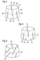
- FIG. 4 shows a compensation element according to a first embodiment of the invention.
- incisions 70 are formed starting from its lower edge 60, which extend in the direction of the upper edge 62 continuously from the inner surface 44 to the outer surface 46, but before this end, wherein they extend at least beyond the equatorial plane 64, ie the plane bisecting the length of the hollow body and perpendicular to the central axis 42 (FIG. FIG. 3 ) runs.
- incisions 72 extending in the direction of the lower edge 60 are formed, which terminate before the lower edge 60, but in turn extend beyond the equatorial plane 64. Both the cuts 70 and the incisions 72 are perpendicular to the lower edge 60 and to the upper edge 62 of the hollow body 40. In this case, incisions 70 and 72 alternate around the circumference of the hollow body 40.
- incisions 70, 72 are formed with the same length
- Incisions 74 which are significantly shorter than the incisions 70 and 72 and also do not extend to the equatorial plane 64. These shorter cuts 74 serve to further improve the flexibility of the compensation element in the region of the lower edge 60, without significantly impairing the overall strength.
- FIG. 6 Another embodiment is in FIG. 6 shown in the oblique incisions 76, 78 each extend to the opposite edge and thereby extend beyond a plane of flexibility 66 which lies below the equatorial plane 64.
- a plane of flexibility 66 which lies below the equatorial plane 64.
- Such a plane does not necessarily have to be perpendicular to the central axis 42 (FIG. FIG. 3 ) of the hollow body 40, but may be inclined to this.
- FIG. 7 in which a flexibility-securing plane 68 or its surface normal lies at an angle to the central axis and thus also does not run parallel to the lower edge 60 or upper edge 62 of the hollow body 40.
- This arrangement can be advantageous if, in certain areas of the connection to be produced between two components, a particularly large welding area is necessary.
- the cuts have been shown as elongated slots with parallel boundary walls.
- the slots can expand to the lower edge or the upper edge of the hollow body, have different widths, etc.
- the embodiment of an incision has been particularly advantageous exposed in the FIG. 8 is shown.
- the incision 90 is keyhole-like in plan view, ie, starting from, for example, the lower edge 60 of the hollow body 40, the incision 90 tapers in the direction of the flexibility-securing plane and opens into a circular cutout 92, which essentially serves to displace displaced material of the Take compensating element.
- FIG. 9 shows an embodiment of a compensating element similar to that of FIG. 4 in which on the inner surface 44 and on the outer surface 46 in each case a heating coil 54 or 56 is applied, which is guided meander-shaped around the circumference of the hollow body 40.
- the meander is guided so that the main length of the Schuetzldrähte substantially in the direction of the central axis 42 (FIG. FIG. 3 ) or in the longitudinal direction of the incisions 70, 72 extends.
- This embodiment has the advantage that almost the entire surface of the compensating element can be covered with heating wire; However, it is difficult to realize manufacturing technology, since the tool must often be performed by a 180 ° -Kehre for introducing the heating coil.
- FIG. 10 shows how the heating coil is formed as a bifilar element, in which the contact terminals for applying energy are close to each other.
- FIG. 11 a modular structure of the heating coil, in which a plurality of heating elements independently energized and used for welding.
- FIG. 12 illustrating a compensation element according to FIG. 4 shows.
- the main length of the wires extends substantially in the direction of the equatorial plane 64. Since no 180 ° -Kehren are provided except for a Wendeschleife, this type of arrangement is technically easier to accomplish.
- the heating element on the inner surface 44 of the compensating element is guided congruent to the heating element on the outer surface 46 of the compensating element.
Landscapes
- Engineering & Computer Science (AREA)
- Mechanical Engineering (AREA)
- Physics & Mathematics (AREA)
- Thermal Sciences (AREA)
- General Engineering & Computer Science (AREA)
- Textile Engineering (AREA)
- Lining Or Joining Of Plastics Or The Like (AREA)
- Crystals, And After-Treatments Of Crystals (AREA)
Description
- Die Erfindung betrifft ein Ausgleichselement zum Verbinden von Bauteilen aus schmelzbarem Kunststoff, das als zumindest abschnittsweise konisch gestalteter Hohlzylinder ausgebildet ist, mit wenigstens einem Heizelement, das bei Beaufschlagung mit Energie die Innenfläche oder die Außenfläche des Ausgleichselementes oder beide mindestens bereichsweise zum Herstellen einer Schweißverbindung mit den Bauteilen heizt.
- Derartige Ausgleichselemente, auch als Heizmuffen oder Schweißmuffen bezeichnet, sind seit langem bekannt. Sie dienen hauptsächlich zur Herstellung nicht lösbarer Verbindungen zwischen Kunststoffrohren oder Kunststoffrohren und ihrer Fittings.
- So zeigt die
FR-A-1 416 207 - Die
DE-A-24 19 893 offenbart eine Rohrverbindung mit Hilfe einer Doppelmuffe, deren Innenseiten kegelstumpfförmig gestaltet sind. Die zu verbindenden Rohre werden von beiden Seiten in die Doppelmuffe geschoben und mittels eines nicht näher beschriebenen konischen Verbindungselementes, dort als Schweißverbindung oder Schweißglied bezeichnet, miteinander verschweißt. - Bei der Vorgehensweise gemäß der
DE-A-34 22 074 werden, ähnlich wie bei derFR-A-1 416 207 - Die
JP-B-52 066 582 - Eine weitere konische Schweißmuffe, die gelocht oder als Netz ausgebildet sein kann, ist in der
US 3 061 503 gezeigt. - Ein Ausgleichselement bzw. eine Muffe der eingangs genannten Gattung ist insbesondere aus der
WO 02/11973 - Die
DE 10 81 288 offenbart ein Verfahren zum Verbinden eines Rohres und einer Muffe unter Zwischenschaltung einer keilförmigen Schweißhülse. Eine konische Außenfläche der Hülse ist dabei in die konische Innenfläche der Muffe eingepaßt, so daß die Hülse nach dem schlüssigen Zusammenstecken von Rohr, Muffe und Hülse um einige Millimeter aus der Muffe herausragt. Während des Schweißvorganges wird die Hülse mittels einer Zange in den Konus der Muffe hineingedrückt. - Die
JP 06 00 2797 A - Bei geringen Rohrdurchmessern haben sich derartige Ausgleichselemente durchaus bewährt. Bei höheren Rohrdurchmessern jedoch, die durchaus in der Größenordnung von 1000 mm oder darüber liegen können, sind die Fertigungstoleranzen so groß, daß Spalte zwischen den Bauteilen auftreten, welche das fluiddichte Verschweißen erschweren, wenn nicht gar verhindern, und dies trotz der Konizität der Muffe, welche auch ohne vorangehende Kalibrierung der zu verbindenden Bauteile für einen gewissen Toleranzausgleich sorgt. Das Problem verschärft sich noch, wenn beispielsweise ein Rohr unrund ist.
- Dieses Problem wird durch eine Muffentechnik gelöst, bei der ein Ausgleichselement mit den Merkmalen des Anspruchs 1 verwendet wird. Vorteilhafte Ausgestaltungen sind Gegenstand der rückbezogenen Unteransprüche. Verfahren zum Verbinden von Bauteilen aus schmelzbarem Kunststoff, bei denen die erfindungsgemäßen Ausgleichselemente verwendet werden, sind Gegenstand der Ansprüche 11 bis 14.
- Das Ausgleichselement dieser Muffentechnik zeichnet sich dadurch aus, daß, ausgehend von jeder Randkante, Einschnitte im wesentlichen in axialer Richtung eingebracht sind, wobei zumindest ein Teil der Einschnitte sich bis nahe an oder über eine flexibilitätssichernde Ebene des Ausgleichselementes hinaus erstreckt. Erfindungsgemäß ist vorgesehen, dass der Hohlkörper um seine Mittelachse axialsymmetrisch ausgebildet ist und seine Innenfläche parallel zu seiner Mittelachse verläuft, während seine Außenfläche unter einem bestimmten Winkel zu der Mittelachse verläuft. Des weiteren sollen erste Einschnitte, die von der ersten Randkante ausgehen, und zweite Einschnitte, die von der zweiten Randkante ausgehen, vorliegen, die sich jeweils bis nahe an oder über die flexibilitätssichernde Ebene hinaus erstrecken. Um zu vermeiden, daß bei ungünstiger Anordnung der Einschnitte ein die Flexibilität des Ausgleichselementes nachteilig beeinflussender, das Ausgleichselement umlaufender Bereich verbleibt, wird vorab eine flexibilitätssichernde Ebene definiert, die als Schnittfläche mit dem Ausgleichselement einen vollständigen Kreis oder eine vollständige Ellipse enthält, deren Flächennormale also parallel zur Mittelachse des Hohlkörpers ist oder einen bestimmten Winkel mit ihr bildet. Aus fertigungstechnischen Gründen, auch was das Einbringen der Einschnitte betrifft, wird die Flächennormale der flexibilitätssichernden Ebene im Regelfall parallel zur Mittelachse des Hohlkörpers liegen, so daß sie selbst parallel zu den Randkanten des Hohlkörpers ist. Beispielweise kann die flexibilitätssichernde Ebene die Äquatorebene des Hohlkörpers sein.
- Wesentlich ist immer, daß sich ein Teil der Einschnitte jeweils bis mindestens nahe an oder über die flexibilitätssichernde Ebene erstreckt. Durch die somit gezielte Führung der Einschnitte in axialer Richtung wird das Ausgleichselement in hinreichendem Maße flexibel, daß es sozusagen im Rohr wandern kann, um jegliche auftretende Spalte zu schließen. So wird der vermeintliche Nachteil gegenüber einer Standard-Muffenschweißung, nämlich das Doppelschweißen, also das Schweißen auf beiden Seiten des Ausgleichselementes, ausgeglichen, so daß die Schweißzeit wegen des geringeren Spaltes sogar eher kürzer wird.
- Überdies können auch Sonderrohre, wie Mehrschichtrohre, Verbundrohre usw., die aufgrund ihrer Bauart nur geringe Spalte über Wärmeausdehnung ausgleichen bzw. überbrücken, mit der neuen Muffentechnik einfach geschweißt werden.
- Nach einer vorteilhaften Ausgestaltung sind die von einer ersten Randkante ausgehenden Einschnitte gegenüber den von der zweiten Randkante ausgehenden Einschnitten in Umfangsrichtung des Ausgleichselementes versetzt angeordnet, weiter bevorzugt auch alternierend, wobei abwechselnd ein Einschnitt von der ersten Randkante aus an oder über die flexibilitätssichernde Ebene verläuft, dann ein Einschnitt von der zweiten Randkante her, wieder ein Abschnitt von der ersten Randkante her usw.
- Die Einschnitte können senkrecht zur jeweiligen Randkante verlaufend angeordnet sein oder schräg dazu verlaufen. Sie können gleich oder unterschiedlich lang sein, beispielsweise kann vorgesehen sein, daß nur jeder zweite oder dritte der Einschnitte sich von einer der Randkanten her über die flexibilitätssichernde Ebene hinaus erstreckt.
- Auch die Formgebung der Einschnitte ist allenfalls fertigungstechnischen Grenzen unterworfen. Sie können gradlinig sein oder gekrümmt, sie können über ihren Verlauf die gleiche Breite oder eine variierende Breite aufweisen. Es hat sich herausgestellt, daß beste Ergebnisse erreicht werden, wenn die Einschnitte mit einer schlüssellochartigen Kontur gebildet sind.
- Als Heizelement sind Metallgitter, Metallfäden, Metallpartikel oder Metalldrähte geeignet, aber auch eine Schicht oder ein Leiter aus elektrisch leitendem Kunststoff, wobei die Einbringung der Energie mittels Stromfluß oder Induktion oder Mikrowellentechnologie erfolgt.
- Vorzugsweise ist das mindestens eine Heizelement eine Heizwendel, so daß mit einer bewährten Technologie gearbeitet werden kann. Um eine ausreichende Heizfläche zur Verfügung zu stellen, ist es zweckmäßig, die Heizwendel mäanderförmig zwischen den Einschnitten zu führen. Dies kann geschehen, indem das Mäander so geführt wird, daß die Hauptlänge der Drähte sich im wesentlichen in die Richtung der Äquatorebene erstreckt oder aber, daß sich die Hauptlänge im wesentlichen senkrecht dazu erstreckt.
- Das Heizelement kann dabei als bifilares Element ausgebildet sein, bei dem sich die Kontaktanschlüsse zum Beaufschlagen mit Energie nahe beieinander befinden.
- Mehrere Heizelemente können verwendet werden, die unabhängig voneinander mit Energie zu beaufschlagen sind.
- Das Ausgleichselement wird vorzugsweise in Verbindung mit einer Außenhülse verwendet, um eine Muffe zu bilden, wobei Muffe hier als ein Bauteil zur unterbrechungsfreien Verbindung beispielsweise zweier Rohre zu verstehen ist. Die Außenhülse ist grundsätzlich längenvariabel und daher vielseitig einsetzbar. Sie kann zum Beispiel auch dazu dienen, ein nicht bewickeltes T-Stück mit einem Rohr zu verbinden. Die Außenhülse kann auch so aufgebaut sein, daß die Hülsenwinkel unter einem Winkel zueinander angeordnet sind. Es können auch die Hülsenenden wie die Außenhülsen unterschiedliche Innendurchmesser aufweisen. Für die Verzweigung mehrerer Rohrleitungen sind Y- oder T-förmige Hülsen möglich. Außen wie auch innen in der Außenhülse kann ein Anschlag ausgebildet sein, beispielsweise in Form eines Ringflansches, der dafür sorgt, daß die Bauteile eine definierte Position in der Außenhülse annehmen. Bei Hochdruckanwendungen ist eine Armierung der Außenhülse mit Fasern zweckmäßig. Die Außenhülse und das Ausgleichselement bestehen selbst aus einem schmelzbaren Kunststoff, der mit dem schmelzbaren Kunststoff der Bauteile kompatibel ist.
- Ein Verfahren zum Verbinden von Bauteilen aus schmelzbarem Kunststoff weist folgende Schritte auf:
- a) Bereitstellen einer Muffe aus einer Außenhülse und einem darinliegenden Ausgleichselement nach einem der Ansprüche 1 bis 10;
- b) Aufschieben der Muffe auf ein Bauteil, wobei sich die Außenhülse und das Ausgleichselement axial gegenläufig verschieben und Spalte zwischen Bauteil und Ausgleichselement sowie zwischen Ausgleichselement und Außenhülse minimiert werden;
- c) Beaufschlagen des Heizelementes der Innenfläche des Ausgleichselementes mit Energie, um das Bauteil und das Ausgleichselement miteinander zu verschweißen;
- d) Beaufschlagen des Heizelementes der Außenfläche des Ausgleichselementes mit Energie, um die Außenhülse und das Ausgleichselement miteinander zu verschweißen.
- Die Schritte c) und d) können gleichzeitig oder auch vertauscht durchgeführt werden.
- Bei diesem Verfahren kann der Schritt c) aus den Teilschritten
- c1) Beaufschlagen des Heizelementes der Innenfläche des Ausgleichselementes mit einer ersten Energiemenge, um das Bauteil vorzuwärmen; und
- c2) Beaufschlagen des Heizelementes der Innenfläche des Ausgleichselementes mit einer zweiten Energiemenge, um das Bauteil und das Ausgleichselement miteinander zu verschweißen bestehen.
- Ebenso kann der Schritt d) aus den Teilschritten
- d1) Beaufschlagen des Heizelementes der Außenfläche des Ausgleichselementes mit einer ersten Energiemenge, um die Außenhülse vorzuwärmen; und
- d2) Beaufschlagen des Heizelementes der Außenfläche des Ausgleichselementes mit einer zweiten Energiemenge, um das Bauteil und das Ausgleichselement miteinander zu verschweißen,
- So besteht die Möglichkeit, die Bauteilanpassung durch die axiale Verschiebung des keilförmigen Ausgleichselementes mittels Wärmeeintrag zu unterstützen, ohne daß Rundungsschellen nötig wären. Auch das Abschälen der Ovalität, wie es im Stand der Technik ist, mit dem Nachteil, daß das Bauteil geschwächt wird, ist nicht mehr erforderlich.
- Ein weiteres Verfahren zum Verbinden von Bauteilen aus schmelzbarem Kunststoff, das bei Reparaturen und nachträglichem Einbau einzusetzen ist, weist folgende Schritte auf:
- a) Bereitstellen einer Muffe aus einer Außenhülse und zwei darinliegenden Ausgleichselementen nach einem der Ansprüche 1 bis 10;
- b) vollständiges Aufschieben der Muffe auf ein erstes Bauteil;
- c) Anlegen eines zweiten Bauteils an das erste Bauteil;
- d) Verschieben der Muffe in axialer Richtung über die Anlagestelle zwischen dem ersten Bauteil und dem zweiten Bauteil, so daß eines der Ausgleichselemente über dem ersten Bauteil liegt und das andere Ausgleichselement über dem zweiten Bauteil liegt;
- e) gleichzeitiges oder aufeinanderfolgendes Verschieben der Ausgleichselemente in axialer Richtung aufeinander zu; und
- f) Beaufschlagen der Heizelemente von Innenfläche und Außenfläche der Ausgleichselemente gleichzeitig oder nacheinander mit Energie, um das erste Bauteil, die Muffe und das zweite Bauteil miteinander zu verschweißen.
- "Vollständiges Aufschieben" meint dabei, daß die Außenhülse mitsamt den beiden Ausgleichselementen auf dem ersten Bauteil sitzen.
- Muß beispielsweise eine Rohrleitung repariert werden, so kann der Bereich, der die Leckage zeigt, herausgetrennt werden, anschließend wird über beide freiliegenden Rohrenden jeweils eine Muffe gezogen. Ein Reparaturstück wird dann zwischen die beiden Rohrenden gesetzt, anschließend werden die Muffen, wie im Schritt d) beschrieben, über die Anlagestellen von Rohrenden und Reparaturstück geschoben. Das Verschieben der Ausgleichselemente zum Verkeilen kann mechanisch oder hydraulisch geschehen. Anstelle des Reparaturstückes kann auch ein T-Stück oder ein anderes Bauteil eingesetzt werden.
- Im folgenden soll die Erfindung anhand der beigefügten Zeichnung näher erläutert werden, wobei:
- Figur 1
- in schematischer Weise zeigt, wie beim Einsetzen eines Rohres in ein Anschlußstück ein Montagespalt entsteht;
- Figur 2
- die Verwendung der Muffentechnik zeigt;
- Figur 3
- eine Längsschnittansicht eines als Schiebemuffe ausgebildeten konischen Augleichselementes ist;
- Figur 4
- eine perspektivische Ansicht einer ersten Ausführungsform eines Ausgleichselementes gemäß der vorliegenden Erfindung ist;
- Figur 5
- eine perspektivische Darstellung einer zweiten Ausführungsform eines Ausgleichselementes gemäß der vorliegenden Erfindung ist;
- Figur 6
- eine perspektivische Darstellung einer dritten Ausführungsform eines Ausgleichselementes gemäß der vorliegenden Erfindung ist;
- Figur 7
- eine Darstellung einer vierten Ausführungsform eines Ausgleichselementes gemäß der vorliegenden Erfindung ist;
- Figur 8
- eine Draufsicht auf eine vorteilhafte Schlitzgeometrie ist.
- Figur 9
- eine perspektivische Darstellung eines Ausgleichselementes gemäß der vorliegenden Erfindung ist, bei einer Heizwendelanordnung gemäß einer ersten Ausführungsform der Erfindung verwendet werden;
- Figur 10
- eine Detaildarstellung der Heizwendel ist, die bei dem Ausgleichselement der
Figur 8 verwendet wird; - Figur 11
- einen modularen Heizwendelaufbau zeigt; und
- Figur 12
- ein Ausgleichselement nach
Figur 4 zeigt, bei der eine Heizwendelanordnung nach einer zweiten Ausführungsform der Erfindung eingebracht ist. - Die Zeichnungen sind schematische Darstellungen und nicht notwendig maßstabsgetreu.
-
Figur 1 zeigt stark schematisiert und teilweise weggeschnitten ein Rohr 1, das in ein Anschlußstück oder einen Muffenkörper 2 eingeschoben ist. Aufgrund von Fertigungstoleranzen und Montagebedingungen wird üblicherweise ein Montagespalt 3 zwischen dem Rohr 1 und dem Anschlußstück 2 entstehen, der für eine fluiddichte Verbindung verschlossen werden muß. Zum Verbinden eines Rohres 1 mit einem Anschlußstück oder einem Muffenkörper 2 wird, wieFigur 2 zeigt, ein konusartiges Ausgleichselement 4, hier eine Schiebemuffe, zunächst über das Rohr 1 geschoben, woraufhin dann das Anschlußstück 2 aufgesetzt wird. Die Ausgleichselement 4 wird in den Übergangsbereich zwischen Rohr 1 und Rohr 2 gebracht und dort verschweißt. - Die grundsätzliche Geometrie eines als Schiebemuffe zu verwendenden Ausgleichselementes 4 ist in
Figur 3 in einer Längsschnittansicht gezeigt. Das Ausgleichselement 4 besteht aus einem konisch gestalteten Hohlzylinder 40, der um seine Mittelachse 42 axial symmetrisch ausgebildet ist. Die Innenfläche 44 ist parallel zu der Mittelachse 42, während die Außenfläche 46 unter einem bestimmten Winkel zur Mittelachse 42 verläuft. Mindestens ein Heizelement 50, 52, sehr schematisch angedeutet durch die Punkt-Strich-Linie bzw. die Punkt-Doppelstrich-Linie ist auf der Innenfläche 44 bzw. der Außenfläche 46 des Hohlkörpers 40 vorgesehen. Als Heizelement sind Metallgitter, Metallfäden, Metallpartikel oder Metalldrähte geeignet, aber auch eine Schicht oder ein Leiter aus elektrisch leitendem Kunststoff. Das Ausgleichselement 4 kann auch insgesamt aus leitendem Kunststoff bestehen. Es ist zweckmäßig, für Innenfläche 44 und der Außenfläche 46 getrennt mit Energie beaufschlagbare Heizelemente 50 bzw. 52 vorzusehen, es ist aber auch möglich, einen leitenden Kontakt zwischen den Heizelementen 50 und 52 herzustellen, so daß diese nur gemeinsam mit Energie zu beaufschlagen sind. - Wenn im folgenden von "Unterkante" und "Oberkante" die Rede ist, so sollen darunter jeweils die Randkanten des Ausgleichselementes verstanden werden, die beim Betrachten der Zeichnungsfiguren unten bzw. oben liegen. Es ist also die Unterkante des Ausgleichselementes diejenige, die beim konisch gestalteten Hohlkörper den größeren Radius hat, die Oberkante ist die mit dem kleineren Radius.
-
Figur 4 zeigt ein Ausgleichselement nach einer ersten Ausführungsform der Erfindung. In den konisch gestalteten Hohlkörper 40 sind ausgehend von seiner Unterkante 60 Einschnitte 70 ausgebildet, die sich in Richtung auf die Oberkante 62 durchgehend von der Innenfläche 44 zur Außenfläche 46 erstrecken, aber vor dieser enden, wobei sie mindestens über die Äquatorialebene 64 hinaus verlaufen, also der Ebene, die die Länge des Hohlkörpers halbiert und senkrecht zu der Mittelachse 42 (Figur 3 ) verläuft. Ebenso sind ausgehend von der Oberkante 62 des Hohlkörpers 40 sich in Richtung auf die Unterkante 60 erstreckende Einschnitte 72 ausgebildet, die vor der Unterkante 60 enden, sich aber wiederum über die Äquatorialebene 64 hinaus erstrecken. Sowohl die Einschnitte 70 als auch die Einschnitte 72 verlaufen senkrecht zur Unterkante 60 bzw. zur Oberkante 62 des Hohlkörpers 40. Dabei wechseln sich Einschnitte 70 und 72 um den Umfang des Hohlkörpers 40 ab. - Während bei der Ausführungsform der
Figur 5 alle Einschnitte 70, 72 mit gleicher Länge gebildet sind, weist die Ausführungsform nachFigur 5 Einschnitte 74 auf, die deutlich kürzer sind als die Einschnitte 70 und 72 und sich auch nicht bis zur Äquatorialebene 64 erstrecken. Diese kürzeren Einschnitte 74 dienen dazu, die Flexibilität des Ausgleichselementes im Bereich der Unterkante 60 weiter zu verbessern, ohne die Festigkeit insgesamt wesentlich zu beeinträchtigen. - Wie bereits eingangs erläutert ist es erfindungswesentlich, daß nirgendwo im Hohlkörper ein geschlossener, umlaufender "Ring" entsteht, der nur schwer verformbar wäre. Die Ausführungsformen nach den
Figuren 4 und 5 stellen dies dadurch sicher, daß die Einschnitte 70 und 72 sich jeweils von unterschiedlicher Richtung her über die Äquatorialebene 64 hinaus erstrecken. Unter bestimmten Umständen, beispielsweise bei relativ geringen Wanddicken, kann auch daran gedacht werden, daß die Einschnitte kurz vor der flexibilitätssichernde Ebene enden, wodurch zwar ein geschlossener, aber dennoch verformbarer "Ring" verbleibt. - Eine weitere Ausführungsform ist in
Figur 6 gezeigt, bei der schräg verlaufende Einschnitte 76, 78 sich jeweils auf die gegenüberliegende Kante hin erstrecken und dabei über eine Flexibilitätsebene 66 hinaus verlaufen, die unterhalb der Äquatorialebene 64 liegt. Eine solche Ebene muß nicht notwendigerweise senkrecht zur Mittelachse 42 (Figur 3 ) des Hohlkörpers 40 verlaufen, sondern kann zu dieser geneigt sein. Diese Situation ist inFigur 7 dargestellt, bei der eine flexibilitätssichernde Ebene 68 bzw. ihre Flächennormale unter einem Winkel zur Mittelachse liegt und somit auch nicht zur Unterkante 60 bzw. Oberkante 62 des Hohlkörpers 40 parallel verläuft. Dieser Anordnung kann dann vorteilhaft sein, wenn in bestimmten Bereichen der herzustellenden Verbindung zwischen zwei Bauteilen eine besonders große Schweißfläche nötig ist. - Bei den bisher gezeigten Ausführungsformen eines Ausgleichselementes gemäß der vorliegenden Erfindung sind die Einschnitte als langgestreckte Schlitze mit parallelen Begrenzungswänden dargestellt worden. Grundsätzlich sind auch andere Ausgestaltungen der Schlitze möglich, sie können sich zur Unterkante oder zur Oberkante des Hohlkörpers aufweiten, unterschiedliche Breiten aufweisen usw. Als besonders vorteilhaft hat sich jedoch die Ausgestaltung eines Einschnittes herausgestellt, die in
Figur 8 dargestellt ist. Hier ist der Einschnitt 90 in Draufsicht schlüssellochartig, d.h. ausgehend von beispielsweise der Unterkante 60 des Hohlkörpers 40 verjüngt sich der Einschnitt 90 in Richtung auf die flexibilitätssichernde Ebene zu und mündet in einem kreisförmigen Ausschnitt 92, die im wesentlichen dazu dient, beim Zusammenfügen verdrängtes Material des Ausgleichselementes aufzunehmen. -
Figur 9 zeigt ein Ausführungsbeispiel eines Ausgleichselementes ähnlich dem derFigur 4 , bei dem auf der Innenfläche 44 und auf der Außenfläche 46 jeweils eine Heizwendel 54 bzw. 56 aufgebracht ist, die mäanderförmig um den Umfang des Hohlkörpers 40 geführt ist. Bei dieser Ausführungsform ist das Mäander so geführt, daß sich die Hauptlänge der Heizwendeldrähte im wesentlichen in die Richtung der Mittelachse 42 (Figur 3 ) bzw. in die Längsrichtung der Einschnitte 70, 72 erstreckt. Diese Ausgestaltung hat den Vorteil, daß nahezu die gesamte Oberfläche des Ausgleichselementes mit Heizdraht belegt werden kann; sie ist allerdings fertigungstechnisch schwierig zu realisieren, da zum Einbringen der Heizwendel das Werkzeug oftmals um eine 180°-Kehre geführt werden muß. -
Figur 10 zeigt, wie die Heizwendel als bifilares Element ausgebildet ist, bei dem sich die Kontaktanschlüsse zum Beaufschlagen mit Energie nahe beieinander befinden. - Dies ermöglicht, wie in
Figur 11 dargestellt, einen modularen Aufbau der Heizwendel, bei dem mehrere Heizelemente unabhängig voneinander mit Energie beaufschlagt und zur Schweißung verwendet werden können. - Eine weitere Möglichkeit, Heizelemente 58, 58' in Form von Heizdrähten mäanderförmig zwischen den Einschnitten 70, 72 zu führen, ist in
Figur 12 veranschaulicht, die eine Ausgleichselement gemäßFigur 4 zeigt. Hier erstreckt sich die Hauptlänge der Drähte im wesentlichen in die Richtung der Äquatorebene 64. Da bis auf eine Wendeschleife keine 180°-Kehren vorgesehen sind, ist diese Art der Anordnung werkzeugtechnisch einfacher zu bewerkstelligen. Das Heizelement auf der Innenfläche 44 des Ausgleichselementes ist dabei kongruent zu dem Heizelement auf der Außenfläche 46 des Ausgleichselementes geführt. Zwar sind in der Zeichnung lediglich fünf untereinander äquidistant verlaufende Heizdrahtführungen gezeigt, es versteht sich aber, daß bei der praktischen Ausgestaltung so viele Drähte nebeneinander angeordnet werden, daß die für das sichere Verschweißen erforderliche Schweißfläche erreicht wird.
Claims (13)
- Ausgleichselement zum Verbinden von Bauteilen aus schmelzbarem Kunststoff, das als zumindest abschnittsweise konisch gestalteter Hohlkörper (40) ausgebildet ist, wobei der Hohlkörper (40) um seine Mittelachse (42) axialsymmetrisch ausgebildet ist und seine Innenfläche (44) parallel zu seiner Mittelachse (42) verläuft, während seine Außenfläche (46) unter einem bestimmten Winkel zu der Mittelachse (42) verläuft, mit wenigstens einem Heizelement (50, 52, 54, 56, 58, 58'), das darauf ausgelegt ist, bei Beaufschlagung mit Energie die Innenfläche (44) oder die Außenfläche (46) des Ausgleichselementes oder beide mindestens bereichsweise zum Herstellen mit einer Schweißverbindung mit den Bauteilen zu heizen, dadurch gekennzeichnet, dass,
ausgehend von jeder Randkante (60, 62) des Hohlkörpers (40) Einschnitte (70, 72, 74, 76, 80) eingebracht sind, wobei sich zumindest ein Teil der Einschnitte bis nahe an oder über eine vordefinierte flexibilitätssichernde Ebene (64, 66, 68) des Ausgleichselementes hinaus erstreckt, und erste Einschnitte (70), die von der ersten Randkante (60) im wesentlichen in axialer Richtung ausgehen, und zweite Einschnitte (72), die von der zweiten Randkante (62) im wesentlichen in axialer Richtung ausgehen, vorliegen, die sich jeweils bis nahe an oder über die flexibilitätssichernde Ebene hinaus erstrecken;
wobei die flexibilitätssichernde Ebene (64, 66, 68) als Schnittfläche mit dem Ausgleichselement einen vollständigen Kreis oder eine vollständige Ellipse enthält, deren Flächennormale parallel zur Mittelachse (42) des Hohlkörpers (40) verläuft oder einen bestimmten Winkel mit ihr bildet, derart, dass nirgendwo im Hohlkörper (40) ein geschlossener, umlaufender Ring entsteht. - Ausgleichselement nach Anspruch 1, dadurch gekennzeichnet, dass die von einer ersten Randkante (60) ausgehenden Einschnitte (70, 74) gegenüber den von der zweiten Randkante (62) ausgehenden Einschnitten (72) in Umfangsrichtung des Ausgleichselementes versetzt angeordnet sind.
- Ausgleichselement nach Anspruch 1, dadurch gekennzeichnet, dass die Einschnitte (70, 72, 75) senkrecht zu den Randkanten (60, 62) sind.
- Ausgleichselement nach Anspruch 1, dadurch gekennzeichnet, dass die Einschnitte (90) zumindest teilweise mit einer schlüssellochartigen Kontur (90, 92) gebildet sind.
- Ausgleichselement nach Anspruch 1, dadurch gekennzeichnet, dass als Heizelement Metallgitter, Metallfäden, Metallpartikel oder Metalldrähte oder eine Schicht oder ein Leiter aus elektrisch leitendem Kunststoff vorgesehen sind oder dass der Hohlkörper (40) aus elektrisch leitendem Kunststoff besteht, wobei das Heizelement auf die Einbringung der Energie mittels Stromfluss oder Induktion oder Mikrowellentechnologie ausgelegt ist.
- Ausgleichselement nach Anspruch 1, dadurch gekennzeichnet, dass das mindestens eine Heizelement (50, 52, 54, 56, 58, 58') eine Heizwendel ist.
- Ausgleichselement nach Anspruch 6, dadurch gekennzeichnet, dass die Heizwendel mäanderförmig zwischen den Einschnitten (70, 72) geführt ist.
- Ausgleichselement nach Anspruch 1, dadurch gekennzeichnet, dass das Heizelement als ein bifilares Element ausgebildet ist.
- Ausgleichselement nach Anspruch 1, dadurch gekennzeichnet, dass es mehrere Heizelemente aufweist, die unabhängig von einander mit Energie zu beaufschlagen sind.
- Verfahren zum Verbinden von Bauteilen aus schmelzbarem Kunststoff, mit den Schritten:a) Bereitstellen einer Muffe aus einer Außenhülse und einem darin liegenden Ausgleichselement (4) nach einem der Ansprüche 1 bis 9, wobei das Ausgleichselement sowohl auf seiner Innenfläche (44) als auch auf seiner Außenfläche (46) ein Heizelement (50, 52, 54, 56, 58, 58') aufweist;b) Aufschieben der Muffe (4) auf ein Bauteil, wobei sich die Außenhülse und das Ausgleichselement axial gegenläufig verschieben und Spalte zwischen Bauteil und Ausgleichselement sowie zwischen Ausgleichselement und Außenhülse minimiert werden;c) Beaufschlagen des Heizelementes (50, 54, 58) der Innenfläche (44) des Ausgleichselementes mit Energie, um das Bauteil und das Ausgleichselement miteinander zu verschweißen;d) Beaufschlagen des Heizelementes (52, 56, 58') der Außenfläche (46) des Ausgleichselementes mit Energie, um die Außenhülse und das Ausgleichselement miteinander zu verschweißen.
- Verfahren nach Anspruch 10, dadurch gekennzeichnet, dass der Schritt c) folgende Schritte aufweist:c1) Beaufschlagen des Heizelementes (50, 54, 58) der Innenfläche (44) des Ausgleichselementes mit einer ersten Energiemenge, um das erste Bauteil vorzuwärmen;c2) Beaufschlagen des Heizelementes (50, 54, 58) der Innenfläche des Ausgleichselementes mit einer zweiten Energiemenge, um das erste Bauteil und die Ausgleichselement miteinander zu verschweißen.
- Verfahren nach Anspruch 10, dadurch gekennzeichnet, dass der Schritt d) folgende Schritte aufweist:d1) Beaufschlagen des Heizelementes (52, 56, 58') der Außenfläche (46) des Ausgleichselementes mit einer ersten Energiemenge, um die Außenhülse vorzuwärmen; undd2) Beaufschlagen des Heizelementes (52, 56, 58') der Außenfläche des Ausgleichselementes mit einer zweiten Energiemenge, um die Außenhülse und das Ausgleichselement miteinander zu verschweißen.
- Verfahren zum Verbinden von Bauteilen aus schmelzbarem Kunststoff, mit folgenden Schritten:a) Bereitstellen einer Muffe aus einer Außenhülse und zwei darin liegenden Ausgleichselementen nach einem der Ansprüche 1 bis 9, wobei jedes der Ausgleichselemente sowohl auf seiner Innenfläche (44) als auch auf seiner Außenfläche (46) ein Heizelement (50, 52, 54, 56, 58, 58') aufweist;b) vollständiges Aufschieben der Muffe auf ein erstes Bauteil;c) Anlegen eines zweiten Bauteils an das erste Bauteil;d) Verschieben der Muffe in axialer Richtung über die Anlagestelle zwischen dem ersten Bauteil und dem zweiten Bauteil, so dass eines der Ausgleichselemente über dem ersten Bauteil liegt und das andere Ausgleichselement über dem zweiten Bauteil liegt;e) gleichzeitiges oder aufeinanderfolgendes Verschieben der Ausgleichselemente in axialer Richtung aufeinander zu; undf) Beaufschlagen der Heizelemente von Innenfläche und Außenfläche der Ausgleichselemente mit Energie, wodurch das erste Bauteil, die Muffe und das zweite Bauteil miteinander verschweißt werden.
Priority Applications (1)
| Application Number | Priority Date | Filing Date | Title |
|---|---|---|---|
| PL08716382T PL2132024T3 (pl) | 2007-03-21 | 2008-03-08 | Element kompensacyjny do łączenia elementów budowlanych |
Applications Claiming Priority (2)
| Application Number | Priority Date | Filing Date | Title |
|---|---|---|---|
| DE102007014049A DE102007014049B3 (de) | 2007-03-21 | 2007-03-21 | Ausgleichselement zum Verbinden von Bauteilen |
| PCT/EP2008/001870 WO2008113488A2 (de) | 2007-03-21 | 2008-03-08 | Ausgleichselement zum verbinden von bauteilen |
Publications (2)
| Publication Number | Publication Date |
|---|---|
| EP2132024A2 EP2132024A2 (de) | 2009-12-16 |
| EP2132024B1 true EP2132024B1 (de) | 2011-09-28 |
Family
ID=39367707
Family Applications (1)
| Application Number | Title | Priority Date | Filing Date |
|---|---|---|---|
| EP08716382A Active EP2132024B1 (de) | 2007-03-21 | 2008-03-08 | Ausgleichselement zum verbinden von bauteilen |
Country Status (9)
| Country | Link |
|---|---|
| US (1) | US8455067B2 (de) |
| EP (1) | EP2132024B1 (de) |
| CN (1) | CN101715388B (de) |
| AT (1) | ATE526142T1 (de) |
| DE (1) | DE102007014049B3 (de) |
| ES (1) | ES2374416T3 (de) |
| PL (1) | PL2132024T3 (de) |
| RU (1) | RU2453434C2 (de) |
| WO (1) | WO2008113488A2 (de) |
Cited By (1)
| Publication number | Priority date | Publication date | Assignee | Title |
|---|---|---|---|---|
| EP2672162A1 (de) | 2012-06-08 | 2013-12-11 | Georg Fischer Wavin AG | Gerillte Elektroschweissmuffe |
Families Citing this family (11)
| Publication number | Priority date | Publication date | Assignee | Title |
|---|---|---|---|---|
| FR2963654B1 (fr) † | 2010-08-06 | 2013-12-13 | Saipem Sa | Conduite comportant un chemisage interne et un manchon tubulaire de jonction en matiere plastique |
| EP2450176A1 (de) * | 2010-11-04 | 2012-05-09 | Georg Fischer Rohrleitungssysteme AG | Heizwendelschweissfitting |
| DE202013101300U1 (de) | 2013-03-26 | 2013-05-10 | Friatec Aktiengesellschaft | System zum Verbinden von Rohren mit unterschiedlichen Außendurchmessern |
| JP2014188998A (ja) * | 2013-03-28 | 2014-10-06 | Mitsubishi Aircraft Corp | 被修理部の修理方法、修理結果物、および修理装置 |
| US10864683B2 (en) * | 2015-09-18 | 2020-12-15 | Honda Motor Co., Ltd. | Thermal caulking method, thermal caulking device, and caulked material |
| CN107486995B (zh) * | 2016-06-13 | 2019-04-26 | 北京化工大学 | 一种连接件以及利用该连接件粘接聚烯烃导管的方法 |
| US10539174B2 (en) | 2016-12-12 | 2020-01-21 | Goodrich Corporation | Composite joint assembly |
| EP3392025B1 (de) * | 2017-04-20 | 2022-06-22 | Georg Fischer Wavin AG | Heizelementgeometrie zur verwendung in einem bohrsattel |
| EP3839319B1 (de) * | 2018-05-29 | 2023-07-05 | Georg Fischer Rohrleitungssysteme AG | Elektroschweissband, verwendung und verfahren |
| RU2751682C1 (ru) * | 2020-11-18 | 2021-07-15 | Александр Ефимович Прокофьев | Способ сварки пластиковых труб |
| EP4631703A1 (de) * | 2024-04-12 | 2025-10-15 | Ipex Technologies Inc. | Rohrarmatur mit schmelzbarer hülse |
Family Cites Families (25)
| Publication number | Priority date | Publication date | Assignee | Title |
|---|---|---|---|---|
| US3061503A (en) * | 1956-10-29 | 1962-10-30 | Dow Chemical Co | Method of joining pipes by means of an electrically heatable sleeve |
| DE1081288B (de) * | 1958-02-20 | 1960-05-05 | Heinrich Schulz Dipl Ing | Huelsen-Schweissverbindung fuer Kunststoffrohre |
| FR1416217A (fr) | 1964-11-24 | 1965-10-29 | Perfectionnements aux outils de refoulement | |
| FR1416207A (fr) * | 1964-11-30 | 1965-10-29 | American Metal Prod | Accouplement de conduites en matière plastique |
| NL157539B (nl) * | 1973-04-27 | 1978-08-15 | Wavin Bv | Buiskoppelstuk. |
| SE428596B (sv) * | 1975-04-09 | 1983-07-11 | Raychem Corp | Anordning for hopkoppling av substrat exv ror omfattande ett organ av minnesmetall |
| US4387845A (en) * | 1980-10-30 | 1983-06-14 | Mefferd Roy J | Method and apparatus for holding and cooling a metal tube during welding |
| US4436988A (en) * | 1982-03-01 | 1984-03-13 | R & G Sloane Mfg. Co., Inc. | Spiral bifilar welding sleeve |
| DE3422074A1 (de) * | 1984-06-14 | 1986-01-23 | Manfred 6000 Frankfurt Eck | Verfahren zur herstellung nicht loesbarer rohrverbindungen von kunststoffrohren |
| SU1268862A1 (ru) * | 1985-01-10 | 1986-11-07 | Предприятие П/Я Р-6594 | Фасонна часть из пластмассы |
| US4695335A (en) * | 1985-11-08 | 1987-09-22 | R. W. Lyall & Company, Inc. | Method for developing a predetermined fusing temperature in thermoplastic items |
| CH671819A5 (de) * | 1986-07-31 | 1989-09-29 | Meier Schenk Ag | |
| FR2648077B1 (fr) | 1989-06-09 | 1991-10-18 | Boulet D Auria Terlizzi | Procede de raccordement de deux elements tubulaires en matiere plastique par electro-soudage et raccord d'electro-soudage pour la mise en oeuvre de ce procede |
| JPH062797A (ja) | 1992-06-19 | 1994-01-11 | Sekisui Chem Co Ltd | 熱融着継手 |
| GB9226489D0 (en) * | 1992-12-19 | 1993-02-10 | Univ Manchester | A joint |
| GB2319576B (en) * | 1996-11-20 | 2001-02-07 | Uponor Bv | Pipe connector |
| SE509120C2 (sv) * | 1997-04-21 | 1998-12-07 | Kungsoers Plast Ab | Sätt och anordning för att avleda statisk elektricitet vid skarvade plaströr |
| WO1999013256A1 (en) | 1997-09-09 | 1999-03-18 | Moshe Kotzer | Plastic pipe joints and formation thereof |
| WO1999022170A1 (en) | 1997-10-29 | 1999-05-06 | Moshe Kotzer | Pipe joints |
| JPH11270771A (ja) * | 1998-03-23 | 1999-10-05 | Nkk Corp | 複合管の継手構造 |
| DE50106044D1 (de) * | 2000-08-04 | 2005-06-02 | Friatec Ag | Vorrichtung zum verbinden von bauteilen aus schmelzbarem kunststoff |
| DE10211703B4 (de) | 2002-03-16 | 2011-03-10 | Brugg Rohr Ag, Holding | Verfahren zur Herstellung einer feuchtigkeitsdichten Verbindung |
| US6925152B2 (en) * | 2003-05-13 | 2005-08-02 | Ge Medical Systems Global Technology Co., Llc | Target attachment assembly |
| RU2245481C1 (ru) * | 2003-07-23 | 2005-01-27 | Осипов Алексей Петрович | Соединение полимерных армированных труб |
| GB2425337A (en) | 2005-04-22 | 2006-10-25 | Uponor Innovation Ab | Electrofusion fitting to seal barrier layer of composite pipe |
-
2007
- 2007-03-21 DE DE102007014049A patent/DE102007014049B3/de not_active Expired - Fee Related
-
2008
- 2008-03-08 RU RU2009138445/05A patent/RU2453434C2/ru active
- 2008-03-08 ES ES08716382T patent/ES2374416T3/es active Active
- 2008-03-08 PL PL08716382T patent/PL2132024T3/pl unknown
- 2008-03-08 US US12/450,359 patent/US8455067B2/en not_active Expired - Fee Related
- 2008-03-08 WO PCT/EP2008/001870 patent/WO2008113488A2/de not_active Ceased
- 2008-03-08 EP EP08716382A patent/EP2132024B1/de active Active
- 2008-03-08 CN CN200880016703.6A patent/CN101715388B/zh not_active Expired - Fee Related
- 2008-03-08 AT AT08716382T patent/ATE526142T1/de active
Cited By (1)
| Publication number | Priority date | Publication date | Assignee | Title |
|---|---|---|---|---|
| EP2672162A1 (de) | 2012-06-08 | 2013-12-11 | Georg Fischer Wavin AG | Gerillte Elektroschweissmuffe |
Also Published As
| Publication number | Publication date |
|---|---|
| RU2009138445A (ru) | 2011-04-27 |
| CN101715388A (zh) | 2010-05-26 |
| WO2008113488A3 (de) | 2009-01-22 |
| DE102007014049B3 (de) | 2008-12-04 |
| RU2453434C2 (ru) | 2012-06-20 |
| CN101715388B (zh) | 2014-04-30 |
| US20100101718A1 (en) | 2010-04-29 |
| EP2132024A2 (de) | 2009-12-16 |
| PL2132024T3 (pl) | 2012-02-29 |
| WO2008113488A2 (de) | 2008-09-25 |
| ATE526142T1 (de) | 2011-10-15 |
| US8455067B2 (en) | 2013-06-04 |
| ES2374416T3 (es) | 2012-02-16 |
Similar Documents
| Publication | Publication Date | Title |
|---|---|---|
| DE102007014049B3 (de) | Ausgleichselement zum Verbinden von Bauteilen | |
| EP0531750B1 (de) | Verfahren zum Verschweissen von aus thermoplastischem Kunststoff bestehenden Rohren | |
| DE69311428T2 (de) | Verfahren zur Herstellung eines Widerstandes zum Verschweissen in Form eines Netzes, eine mit diesem Verfahren hergestellter Widerstand für das Zusammenfügen paralleller oder transversaler Kunststoffröhren und damit ausgerüstete Rohrverzweigung | |
| DE69900161T2 (de) | Elektroschweisskupplung | |
| EP1756464B1 (de) | Verbindungsanordnung, insbesondere zum kraftschlüssigen anbinden von mindestens einem faserverbund-bauteil an ein weiteres bauteil | |
| EP0619176A2 (de) | Verfahren zum Verschweissen von aus thermoplastischem Kunststoff bestehenden Rohrstücken | |
| EP2725659B1 (de) | Koaxialkabelbuchse | |
| DE69703856T2 (de) | Kupplung für zwei Metallrohre | |
| EP1396672A1 (de) | Kunststoffrohr | |
| DE102012009615B4 (de) | Verfahren zum Löten und Baugruppe | |
| DE202014003776U1 (de) | Kunststoffrohr | |
| DE4214279C2 (de) | Verbindungselement zum Verschweißen von Rohren | |
| EP3298316B1 (de) | Flanschverbindung für bauteile aus kunststoff, insbesondere für rohrförmige bauteile aus kunststoff | |
| DE102013108881B4 (de) | Muffenverbindung | |
| DE10309695B4 (de) | Montagesystem und Verfahren zur Verbindung von Kunststoffrohren | |
| EP3281737B1 (de) | Verfahren zum verschweissen zweier bauteile, vorzugsweise einer abgasanlage einer brennkraftmaschine, miteinander durch widerstandsschweissen | |
| EP2463080B1 (de) | Heizelement und Verfahren zum Verschweißen von rohrförmigen Kunststoffbauteilen mit einem Heizelement sowie System aus rohrförmigen Bauteilen und Heizelement | |
| DE3600156A1 (de) | Verfahren zur herstellung einer schweissverbindung zwischen kunststoffrohren, mittel zur durchfuehrung dieses verfahrens und rohrverbindung | |
| DE102010027868B4 (de) | Kunststoffrohr | |
| EP0780620A1 (de) | Rohr oder dgl. Formstück mit Elektromuffe, Verfahren zur Herstellung der Elektromuffe und Verfahren zur Herstellung einer Verbindung derartiger Rohre oder dgl. Formstücke | |
| CH690990A5 (de) | Verfahren, Heizmatte und Manschette zum Verbinden von Kunststoffrohren. | |
| DE19818733B4 (de) | Verfahren zum Herstellen eines Verbundrohres sowie Verbundrohr | |
| DE102006004828A1 (de) | Kunststoffrohr für die Durchleitung eines Heiz- oder Kühlmediums, unter Verwendung derartiger Rohre hergestellte Matte sowie Verbindung zwischen der Stirnseite eines derartigen Rohres und einem Kunststoffkörper | |
| WO2013013664A2 (de) | Verbundkomponenten-koppelsystem und verfahren zum vorbereiten der kopplung einer verbundkomponente an eine weitere komponente | |
| DE102016110769A1 (de) | Fügeverbindung und -verfahren für Schweißbrennerbauteile |
Legal Events
| Date | Code | Title | Description |
|---|---|---|---|
| PUAI | Public reference made under article 153(3) epc to a published international application that has entered the european phase |
Free format text: ORIGINAL CODE: 0009012 |
|
| 17P | Request for examination filed |
Effective date: 20090922 |
|
| AK | Designated contracting states |
Kind code of ref document: A2 Designated state(s): AT BE BG CH CY CZ DE DK EE ES FI FR GB GR HR HU IE IS IT LI LT LU LV MC MT NL NO PL PT RO SE SI SK TR |
|
| 17Q | First examination report despatched |
Effective date: 20100331 |
|
| GRAP | Despatch of communication of intention to grant a patent |
Free format text: ORIGINAL CODE: EPIDOSNIGR1 |
|
| DAX | Request for extension of the european patent (deleted) | ||
| GRAS | Grant fee paid |
Free format text: ORIGINAL CODE: EPIDOSNIGR3 |
|
| GRAA | (expected) grant |
Free format text: ORIGINAL CODE: 0009210 |
|
| AK | Designated contracting states |
Kind code of ref document: B1 Designated state(s): AT BE BG CH CY CZ DE DK EE ES FI FR GB GR HR HU IE IS IT LI LT LU LV MC MT NL NO PL PT RO SE SI SK TR |
|
| REG | Reference to a national code |
Ref country code: GB Ref legal event code: FG4D Free format text: NOT ENGLISH |
|
| REG | Reference to a national code |
Ref country code: CH Ref legal event code: EP Ref country code: CH Ref legal event code: NV Representative=s name: KAMINSKI HARMANN PATENTANWAELTE EST. |
|
| REG | Reference to a national code |
Ref country code: IE Ref legal event code: FG4D |
|
| REG | Reference to a national code |
Ref country code: DE Ref legal event code: R096 Ref document number: 502008005029 Country of ref document: DE Effective date: 20111222 |
|
| REG | Reference to a national code |
Ref country code: NL Ref legal event code: VDEP Effective date: 20110928 |
|
| PG25 | Lapsed in a contracting state [announced via postgrant information from national office to epo] |
Ref country code: HR Free format text: LAPSE BECAUSE OF FAILURE TO SUBMIT A TRANSLATION OF THE DESCRIPTION OR TO PAY THE FEE WITHIN THE PRESCRIBED TIME-LIMIT Effective date: 20110928 Ref country code: FI Free format text: LAPSE BECAUSE OF FAILURE TO SUBMIT A TRANSLATION OF THE DESCRIPTION OR TO PAY THE FEE WITHIN THE PRESCRIBED TIME-LIMIT Effective date: 20110928 Ref country code: NO Free format text: LAPSE BECAUSE OF FAILURE TO SUBMIT A TRANSLATION OF THE DESCRIPTION OR TO PAY THE FEE WITHIN THE PRESCRIBED TIME-LIMIT Effective date: 20111228 Ref country code: SE Free format text: LAPSE BECAUSE OF FAILURE TO SUBMIT A TRANSLATION OF THE DESCRIPTION OR TO PAY THE FEE WITHIN THE PRESCRIBED TIME-LIMIT Effective date: 20110928 Ref country code: LT Free format text: LAPSE BECAUSE OF FAILURE TO SUBMIT A TRANSLATION OF THE DESCRIPTION OR TO PAY THE FEE WITHIN THE PRESCRIBED TIME-LIMIT Effective date: 20110928 |
|
| REG | Reference to a national code |
Ref country code: SK Ref legal event code: T3 Ref document number: E 10511 Country of ref document: SK |
|
| REG | Reference to a national code |
Ref country code: ES Ref legal event code: FG2A Ref document number: 2374416 Country of ref document: ES Kind code of ref document: T3 Effective date: 20120216 |
|
| LTIE | Lt: invalidation of european patent or patent extension |
Effective date: 20110928 |
|
| PG25 | Lapsed in a contracting state [announced via postgrant information from national office to epo] |
Ref country code: CY Free format text: LAPSE BECAUSE OF FAILURE TO SUBMIT A TRANSLATION OF THE DESCRIPTION OR TO PAY THE FEE WITHIN THE PRESCRIBED TIME-LIMIT Effective date: 20110928 Ref country code: LV Free format text: LAPSE BECAUSE OF FAILURE TO SUBMIT A TRANSLATION OF THE DESCRIPTION OR TO PAY THE FEE WITHIN THE PRESCRIBED TIME-LIMIT Effective date: 20110928 Ref country code: SI Free format text: LAPSE BECAUSE OF FAILURE TO SUBMIT A TRANSLATION OF THE DESCRIPTION OR TO PAY THE FEE WITHIN THE PRESCRIBED TIME-LIMIT Effective date: 20110928 |
|
| REG | Reference to a national code |
Ref country code: PL Ref legal event code: T3 |
|
| REG | Reference to a national code |
Ref country code: GR Ref legal event code: EP Ref document number: 20110402793 Country of ref document: GR Effective date: 20120117 |
|
| REG | Reference to a national code |
Ref country code: IE Ref legal event code: FD4D |
|
| PG25 | Lapsed in a contracting state [announced via postgrant information from national office to epo] |
Ref country code: IS Free format text: LAPSE BECAUSE OF FAILURE TO SUBMIT A TRANSLATION OF THE DESCRIPTION OR TO PAY THE FEE WITHIN THE PRESCRIBED TIME-LIMIT Effective date: 20120128 |
|
| PG25 | Lapsed in a contracting state [announced via postgrant information from national office to epo] |
Ref country code: EE Free format text: LAPSE BECAUSE OF FAILURE TO SUBMIT A TRANSLATION OF THE DESCRIPTION OR TO PAY THE FEE WITHIN THE PRESCRIBED TIME-LIMIT Effective date: 20110928 Ref country code: RO Free format text: LAPSE BECAUSE OF FAILURE TO SUBMIT A TRANSLATION OF THE DESCRIPTION OR TO PAY THE FEE WITHIN THE PRESCRIBED TIME-LIMIT Effective date: 20110928 Ref country code: NL Free format text: LAPSE BECAUSE OF FAILURE TO SUBMIT A TRANSLATION OF THE DESCRIPTION OR TO PAY THE FEE WITHIN THE PRESCRIBED TIME-LIMIT Effective date: 20110928 Ref country code: PT Free format text: LAPSE BECAUSE OF FAILURE TO SUBMIT A TRANSLATION OF THE DESCRIPTION OR TO PAY THE FEE WITHIN THE PRESCRIBED TIME-LIMIT Effective date: 20120130 |
|
| PG25 | Lapsed in a contracting state [announced via postgrant information from national office to epo] |
Ref country code: DK Free format text: LAPSE BECAUSE OF FAILURE TO SUBMIT A TRANSLATION OF THE DESCRIPTION OR TO PAY THE FEE WITHIN THE PRESCRIBED TIME-LIMIT Effective date: 20110928 Ref country code: IE Free format text: LAPSE BECAUSE OF FAILURE TO SUBMIT A TRANSLATION OF THE DESCRIPTION OR TO PAY THE FEE WITHIN THE PRESCRIBED TIME-LIMIT Effective date: 20110928 |
|
| PLBE | No opposition filed within time limit |
Free format text: ORIGINAL CODE: 0009261 |
|
| STAA | Information on the status of an ep patent application or granted ep patent |
Free format text: STATUS: NO OPPOSITION FILED WITHIN TIME LIMIT |
|
| 26N | No opposition filed |
Effective date: 20120629 |
|
| BERE | Be: lapsed |
Owner name: FRIATEC A.G. Effective date: 20120331 |
|
| REG | Reference to a national code |
Ref country code: DE Ref legal event code: R097 Ref document number: 502008005029 Country of ref document: DE Effective date: 20120629 |
|
| PG25 | Lapsed in a contracting state [announced via postgrant information from national office to epo] |
Ref country code: MC Free format text: LAPSE BECAUSE OF NON-PAYMENT OF DUE FEES Effective date: 20120331 |
|
| REG | Reference to a national code |
Ref country code: DE Ref legal event code: R119 Ref document number: 502008005029 Country of ref document: DE Effective date: 20121002 |
|
| PG25 | Lapsed in a contracting state [announced via postgrant information from national office to epo] |
Ref country code: BE Free format text: LAPSE BECAUSE OF NON-PAYMENT OF DUE FEES Effective date: 20120331 |
|
| PG25 | Lapsed in a contracting state [announced via postgrant information from national office to epo] |
Ref country code: BG Free format text: LAPSE BECAUSE OF FAILURE TO SUBMIT A TRANSLATION OF THE DESCRIPTION OR TO PAY THE FEE WITHIN THE PRESCRIBED TIME-LIMIT Effective date: 20111228 |
|
| PG25 | Lapsed in a contracting state [announced via postgrant information from national office to epo] |
Ref country code: MT Free format text: LAPSE BECAUSE OF FAILURE TO SUBMIT A TRANSLATION OF THE DESCRIPTION OR TO PAY THE FEE WITHIN THE PRESCRIBED TIME-LIMIT Effective date: 20110928 |
|
| PG25 | Lapsed in a contracting state [announced via postgrant information from national office to epo] |
Ref country code: LU Free format text: LAPSE BECAUSE OF NON-PAYMENT OF DUE FEES Effective date: 20120308 |
|
| PG25 | Lapsed in a contracting state [announced via postgrant information from national office to epo] |
Ref country code: HU Free format text: LAPSE BECAUSE OF FAILURE TO SUBMIT A TRANSLATION OF THE DESCRIPTION OR TO PAY THE FEE WITHIN THE PRESCRIBED TIME-LIMIT Effective date: 20080308 |
|
| PG25 | Lapsed in a contracting state [announced via postgrant information from national office to epo] |
Ref country code: DE Free format text: LAPSE BECAUSE OF FAILURE TO SUBMIT A TRANSLATION OF THE DESCRIPTION OR TO PAY THE FEE WITHIN THE PRESCRIBED TIME-LIMIT Effective date: 20121002 |
|
| REG | Reference to a national code |
Ref country code: FR Ref legal event code: PLFP Year of fee payment: 9 |
|
| PGFP | Annual fee paid to national office [announced via postgrant information from national office to epo] |
Ref country code: CZ Payment date: 20160303 Year of fee payment: 9 Ref country code: ES Payment date: 20160229 Year of fee payment: 9 Ref country code: SK Payment date: 20160304 Year of fee payment: 9 |
|
| PGFP | Annual fee paid to national office [announced via postgrant information from national office to epo] |
Ref country code: GR Payment date: 20160229 Year of fee payment: 9 Ref country code: FR Payment date: 20160223 Year of fee payment: 9 |
|
| PG25 | Lapsed in a contracting state [announced via postgrant information from national office to epo] |
Ref country code: CZ Free format text: LAPSE BECAUSE OF NON-PAYMENT OF DUE FEES Effective date: 20170308 |
|
| REG | Reference to a national code |
Ref country code: SK Ref legal event code: MM4A Ref document number: E 10511 Country of ref document: SK Effective date: 20170308 |
|
| REG | Reference to a national code |
Ref country code: FR Ref legal event code: ST Effective date: 20171130 |
|
| PG25 | Lapsed in a contracting state [announced via postgrant information from national office to epo] |
Ref country code: SK Free format text: LAPSE BECAUSE OF NON-PAYMENT OF DUE FEES Effective date: 20170308 Ref country code: FR Free format text: LAPSE BECAUSE OF NON-PAYMENT OF DUE FEES Effective date: 20170331 |
|
| PG25 | Lapsed in a contracting state [announced via postgrant information from national office to epo] |
Ref country code: GR Free format text: LAPSE BECAUSE OF NON-PAYMENT OF DUE FEES Effective date: 20171005 |
|
| REG | Reference to a national code |
Ref country code: ES Ref legal event code: FD2A Effective date: 20180706 |
|
| PG25 | Lapsed in a contracting state [announced via postgrant information from national office to epo] |
Ref country code: ES Free format text: LAPSE BECAUSE OF NON-PAYMENT OF DUE FEES Effective date: 20170309 |
|
| REG | Reference to a national code |
Ref country code: CH Ref legal event code: NV Representative=s name: 24IP LAW GROUP SONNENBERG FORTMANN, CH |
|
| REG | Reference to a national code |
Ref country code: CH Ref legal event code: NV Representative=s name: BOVARD SA NEUCHATEL CONSEILS EN PROPRETE INTEL, CH Ref country code: CH Ref legal event code: PFA Owner name: FRIATEC GMBH, DE Free format text: FORMER OWNER: FRIATEC AKTIENGESELLSCHAFT, DE |
|
| REG | Reference to a national code |
Ref country code: CH Ref legal event code: NV Representative=s name: 24IP LAW GROUP SONNENBERG FORTMANN, CH |
|
| REG | Reference to a national code |
Ref country code: AT Ref legal event code: PC Ref document number: 526142 Country of ref document: AT Kind code of ref document: T Owner name: FRIATEC GMBH, DE Effective date: 20190612 |
|
| REG | Reference to a national code |
Ref country code: CH Ref legal event code: PFA Owner name: ALIAXIS DEUTSCHLAND GMBH, DE Free format text: FORMER OWNER: FRIATEC GMBH, DE |
|
| REG | Reference to a national code |
Ref country code: AT Ref legal event code: HC Ref document number: 526142 Country of ref document: AT Kind code of ref document: T Owner name: ALIAXIS DEUTSCHLAND GMBH, DE Effective date: 20200723 |
|
| P01 | Opt-out of the competence of the unified patent court (upc) registered |
Effective date: 20230524 |
|
| PGFP | Annual fee paid to national office [announced via postgrant information from national office to epo] |
Ref country code: AT Payment date: 20240318 Year of fee payment: 17 |
|
| PGFP | Annual fee paid to national office [announced via postgrant information from national office to epo] |
Ref country code: GB Payment date: 20240322 Year of fee payment: 17 |
|
| PGFP | Annual fee paid to national office [announced via postgrant information from national office to epo] |
Ref country code: TR Payment date: 20240228 Year of fee payment: 17 Ref country code: PL Payment date: 20240228 Year of fee payment: 17 Ref country code: IT Payment date: 20240329 Year of fee payment: 17 |
|
| PGFP | Annual fee paid to national office [announced via postgrant information from national office to epo] |
Ref country code: CH Payment date: 20240401 Year of fee payment: 17 |
|
| REG | Reference to a national code |
Ref country code: CH Ref legal event code: H13 Free format text: ST27 STATUS EVENT CODE: U-0-0-H10-H13 (AS PROVIDED BY THE NATIONAL OFFICE) Effective date: 20251023 |
|
| REG | Reference to a national code |
Ref country code: AT Ref legal event code: MM01 Ref document number: 526142 Country of ref document: AT Kind code of ref document: T Effective date: 20250308 |
|
| GBPC | Gb: european patent ceased through non-payment of renewal fee |
Effective date: 20250308 |
|
| PG25 | Lapsed in a contracting state [announced via postgrant information from national office to epo] |
Ref country code: GB Free format text: LAPSE BECAUSE OF NON-PAYMENT OF DUE FEES Effective date: 20250308 |
|
| PG25 | Lapsed in a contracting state [announced via postgrant information from national office to epo] |
Ref country code: AT Free format text: LAPSE BECAUSE OF NON-PAYMENT OF DUE FEES Effective date: 20250308 |
|
| PG25 | Lapsed in a contracting state [announced via postgrant information from national office to epo] |
Ref country code: IT Free format text: LAPSE BECAUSE OF NON-PAYMENT OF DUE FEES Effective date: 20250308 |
|
| PG25 | Lapsed in a contracting state [announced via postgrant information from national office to epo] |
Ref country code: CH Free format text: LAPSE BECAUSE OF NON-PAYMENT OF DUE FEES Effective date: 20250331 |