EP2132576B1 - Adaptateur pour fiole a echantillon - Google Patents
Adaptateur pour fiole a echantillon Download PDFInfo
- Publication number
- EP2132576B1 EP2132576B1 EP08727116.9A EP08727116A EP2132576B1 EP 2132576 B1 EP2132576 B1 EP 2132576B1 EP 08727116 A EP08727116 A EP 08727116A EP 2132576 B1 EP2132576 B1 EP 2132576B1
- Authority
- EP
- European Patent Office
- Prior art keywords
- assembly
- lumen
- vent tube
- sample
- sub
- Prior art date
- Legal status (The legal status is an assumption and is not a legal conclusion. Google has not performed a legal analysis and makes no representation as to the accuracy of the status listed.)
- Active
Links
Images




Classifications
-
- B—PERFORMING OPERATIONS; TRANSPORTING
- B01—PHYSICAL OR CHEMICAL PROCESSES OR APPARATUS IN GENERAL
- B01L—CHEMICAL OR PHYSICAL LABORATORY APPARATUS FOR GENERAL USE
- B01L3/00—Containers or dishes for laboratory use, e.g. laboratory glassware; Droppers
- B01L3/56—Labware specially adapted for transferring fluids
- B01L3/563—Joints or fittings; Separable fluid transfer means to transfer fluids between at least two containers, e.g. connectors
- B01L3/5635—Joints or fittings; Separable fluid transfer means to transfer fluids between at least two containers, e.g. connectors connecting two containers face to face, e.g. comprising a filter
-
- A—HUMAN NECESSITIES
- A61—MEDICAL OR VETERINARY SCIENCE; HYGIENE
- A61B—DIAGNOSIS; SURGERY; IDENTIFICATION
- A61B5/00—Measuring for diagnostic purposes; Identification of persons
- A61B5/15—Devices for taking samples of blood
- A61B5/150007—Details
- A61B5/150015—Source of blood
- A61B5/15003—Source of blood for venous or arterial blood
-
- A—HUMAN NECESSITIES
- A61—MEDICAL OR VETERINARY SCIENCE; HYGIENE
- A61B—DIAGNOSIS; SURGERY; IDENTIFICATION
- A61B5/00—Measuring for diagnostic purposes; Identification of persons
- A61B5/15—Devices for taking samples of blood
- A61B5/150007—Details
- A61B5/150206—Construction or design features not otherwise provided for; manufacturing or production; packages; sterilisation of piercing element, piercing device or sampling device
- A61B5/150213—Venting means
-
- A—HUMAN NECESSITIES
- A61—MEDICAL OR VETERINARY SCIENCE; HYGIENE
- A61B—DIAGNOSIS; SURGERY; IDENTIFICATION
- A61B5/00—Measuring for diagnostic purposes; Identification of persons
- A61B5/15—Devices for taking samples of blood
- A61B5/150007—Details
- A61B5/150351—Caps, stoppers or lids for sealing or closing a blood collection vessel or container, e.g. a test-tube or syringe barrel
-
- A—HUMAN NECESSITIES
- A61—MEDICAL OR VETERINARY SCIENCE; HYGIENE
- A61B—DIAGNOSIS; SURGERY; IDENTIFICATION
- A61B5/00—Measuring for diagnostic purposes; Identification of persons
- A61B5/15—Devices for taking samples of blood
- A61B5/150992—Blood sampling from a fluid line external to a patient, such as a catheter line, combined with an infusion line; Blood sampling from indwelling needle sets, e.g. sealable ports, luer couplings or valves
-
- A—HUMAN NECESSITIES
- A61—MEDICAL OR VETERINARY SCIENCE; HYGIENE
- A61B—DIAGNOSIS; SURGERY; IDENTIFICATION
- A61B5/00—Measuring for diagnostic purposes; Identification of persons
- A61B5/15—Devices for taking samples of blood
- A61B5/153—Devices specially adapted for taking samples of venous or arterial blood, e.g. with syringes
- A61B5/154—Devices using pre-evacuated means
-
- B—PERFORMING OPERATIONS; TRANSPORTING
- B01—PHYSICAL OR CHEMICAL PROCESSES OR APPARATUS IN GENERAL
- B01L—CHEMICAL OR PHYSICAL LABORATORY APPARATUS FOR GENERAL USE
- B01L2200/00—Solutions for specific problems relating to chemical or physical laboratory apparatus
- B01L2200/06—Fluid handling related problems
- B01L2200/0684—Venting, avoiding backpressure, avoid gas bubbles
Definitions
- the invention relates generally to adaptors for transfer of fluids from a container to an instrument, and methods thereof. More particularly, the invention relates to a sample vial adaptor for interfacing a sample vial with the sample port of a diagnostic instrument, in particular a sample vial containing a patient body fluid sample with the sample port and sample pathway of a multi-use diagnostic instrument.
- Renal function testing uses a panel of analytes including Na, iCa, Cl, K, HCO 3 , glucose, lactate, blood urea nitrogen (BUN) and creatinine.
- the renal panel incorporates three measurements also included in a typical electrolyte/metabolite panel, i.e., creatinine, BUN and measured HCO 3 .
- Acute renal failure is defined as an abrupt or rapid decline in renal function. A rise in BUN or creatinine concentrations is usually evidence of ARF. ARF is often transient and completely reversible.
- HCO 3 is a critical parameter in assessing acid-base balance as it relates to renal function. While carbon dioxide (CO 2 ) is the respiratory component in acid-base balance, bicarbonate (HCO 3 ) is the renal component.
- a blood sample vial e.g., a Vacutainer ® (BD) vial, is used for collecting blood samples from patients.
- a blood sample is drawn into a heparinized vial, e.g., a Vacutainer ® vial, aliquotted into syringe(s), and capped prior to transport or upon receipt in the laboratory.
- a heparinized vial e.g., a Vacutainer ® vial
- the sample is prepared in either syringes or poured into smaller cuvettes to accommodate the short sampling probe lengths typical of diagnostic instruments. The short probe length prohibits direct sampling by the diagnostic instrument from an open Vacutainer ® vessel.
- Most multi-use, high volume diagnostic instruments have sample ports that are primarily designed to interface with syringes.
- a common sampling error occurs when a diagnostic instrument aspirates a sample from a capped airtight sample vial. As a volume of sample is withdrawn from the sample vial by the diagnostic instrument, a vacuum is introduced in the vial. When the vial is removed from the sample port of the diagnostic instrument, the pressure in the sample pathway of the instrument equilibrates with the atmosphere causing air to rush into the sample pathway and the sample to be pulled further into the sample pathway past the sample sensor area. A sampling error is triggered and the sample is not measured.
- US 2006/0263250 discloses a telescoping closed-tube sampling assembly for use in a clinical diagnostic sample analyser.
- the analyser includes a telescoping closed-tube assembly with a sample probe concentrically housed within a piercing probe and a venting mechanism.
- the assembly is designed to prevent cross-contamination of blood samples and reduces clogging of both the piercing and sampling mechanisms.”
- sample vial adaptor described herein resolves the sampling error, reduces sample cross-contamination, operator biohazard exposure, and the large sample size needed for current devices and methods for introducing a sample into a diagnostic instrument. Additionally, one end of the sample vial adaptor described herein according to the invention interfaces with a diagnostic instrument sample port in a manner consistent with a capillary sample device.
- the invention relates to a device for removal of a body fluid from a vial, comprising an elongate body sub-assembly including a first portion, a second portion, and an intermediate portion extending from the first portion to the second portion.
- the first portion of the elongate body sub-assembly includes a first cylindrical chamber having a wall surrounding a lumen and at least one hole extending from the lumen through the wall to the exterior of the elongate body.
- the intermediate portion of the elongate body sub-assembly comprises a channel extending from the first cylindrical chamber to the second portion of the elongate body sub-assembly.
- the second portion of the elongate body sub-assembly includes a second chamber narrower than the first chamber.
- the second chamber includes a wall surrounding a lumen.
- the lumen is in fluid communication with the exterior of the elongate body sub-assembly.
- a threaded sub-assembly of the device comprises a first end having a threaded exterior surface, and a second end positioned within the lumen of the first chamber of said elongate body sub-assembly.
- the device according to the invention further includes a vent tube comprising a lumen, a first end, and a second end.
- the vent tube is axially positioned and fixed in the threaded sub-assembly.
- the second end of the vent tube is in fluid communication with the lumen of the first chamber.
- the first end of the vent tube comprises a bevel and extends beyond the first end of the threaded sub-assembly.
- the device further includes a collection tube comprising a lumen, a first end, and a second end.
- the collection tube is axially disposed in the lumen of the vent tube.
- the second end of the collection tube is in fluid communication with the second chamber of the elongate body sub-assembly and the first end of the collection tube extends beyond the first end of the first tube.
- a gap is disposed between the vent tube and the collection tube. The gap is uniform in width and extends along the length of the vent tube.
- the invention relates to a sample vial adaptor for interfacing a sample vial, for example, a sample vial containing a body fluid from a patient, with a sample port of a multi-use, typically high volume diagnostic instrument such as the GEM 4000 marketed by Instrumentation Laboratory Company (Lexington, MA).
- a sample vial adaptor for interfacing a sample vial, for example, a sample vial containing a body fluid from a patient, with a sample port of a multi-use, typically high volume diagnostic instrument such as the GEM 4000 marketed by Instrumentation Laboratory Company (Lexington, MA).
- All of the following embodiments of the sample vial adaptor according to the invention generally have common features including a short exterior vent tube having one end in communication with a chamber having a vent, an interior collection tube that is longer than the short exterior vent tube, axially positioned in the lumen of the short exterior vent tube and extending to a capillary outlet that is located on the portion of the inner collection tube that is outside of the short exterior vent tube and outside the vented chamber.
- the sample vial adaptor according to the invention is advantageous over prior art devices because air flows back into the sample vial, away from the sample input through the vent thereby equilibrating the vial to room atmospheric conditions.
- This equilibration allows an unrestricted flow of sample from the vial into a sample port in the diagnostic instrument and consequently proper sample positioning in the instrument. Without a "breathing" vent, residual vacuum will build up in the closed sample vial during sample aspiration, and upon removal of the sample container, the equalization of the sample path to atmospheric pressure causes the sample to be pulled past the sensor area, triggering a sample detection flag and reported system error.
- sample vial adaptor utilizes a collection tube and vent tube arranged concentrically which minimizes the outer dimension of the combined tubes and permits accurate targeting to and penetration of the center of the vial cap where puncturing is most desirable.
- the concentric arrangement of the tubes enhances their rigidity and aids in penetration of the tubes through the cap.
- the concentric arrangement also aids in manufacturing and ease of assembly of the adaptor.
- the sample vial adaptor 10 includes an elongate body sub-assembly 12, a threaded sub-assembly 14, a vent tube 16, and a collection tube 18.
- the exemplary elongate body sub-assembly 12 has a first portion 20, a second portion 22, and an intermediate portion 24 extending from the first portion 20 to the second portion 22.
- the first portion 20 of the elongate body sub-assembly 12 includes a first chamber 26, for example, a cylindrical chamber.
- the first chamber 26 includes a vent 28 such as a hole that extends from the lumen 30 of the first chamber 26 through the wall 33 of the elongate body sub-assembly 12 to the surface 31 of the elongate body sub-assembly 12.
- the vent 28 allows communication of atmospheric air from outside the first chamber 26 with the first chamber lumen 30.
- the first chamber 26 also serves as a receptacle for the threaded subassembly described below.
- the exemplary vent 28 may be positioned anywhere on the first chamber wall 33.
- the first chamber 26 may have more than one vent 28 such as two, three, four or more vents.
- the shape of the vent 28 may be, for example, cylindrical, rectangular, or funnel shaped, to name a few shapes. Other vent shapes are also contemplated and the vent shape is not limited to the shapes disclosed.
- elongate body sub-assembly 12 includes a channel 32 longitudinally disposed in the intermediate portion 24. Referring to the illustrative embodiment shown in FIG. 2 , the channel 32 extends from the first chamber 26 to the second portion 22 of the elongate body sub-assembly 12. The channel 32 is in fluid communication with the lumen 30 of the first chamber 26. Channel 32 may also receive a portion of the collection tube 18.
- An additional feature of the elongate body sub-assembly 12 includes a second chamber 34, illustrated in FIG. 2 , positioned at the end of the channel 32 opposite to the end of the channel 32 that is in fluid communication with the first chamber 26.
- the second chamber 34 is positioned in the second portion 22 of the elongate body sub-assembly 12 and is in fluid communication with the channel 32.
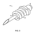
- FIG.3 is a perspective view of an illustrative embodiment of the threaded sub-assembly according to the invention.
- the threaded sub-assembly 14 includes a threaded member 36, a first end 38, and a second end 40.
- the threaded member 36 includes threads spiraling outwardly from the external surface of the threaded member 36. The threads begin at the first end 38 and extend towards but not to the second end 40. The spiral may be right handed or left handed.
- the second end 40 of the threaded member 36 does not include threads and is generally shaped to be received in the first chamber 26 at the first end 20 of the elongate body sub-assembly 12.
- the threads may interlock with a receptacle, for example, a cylindrical holder discussed below with respect to Figure 7 , having corresponding interlocking threads.
- the threaded sub-assembly may include other external interlocking devices such as a snap-lock or other devices in addition to or in place of the threads for interlocking with a corresponding interlocking piece.
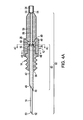
- FIG. 4A is a longitudinal cross-sectional view
- FIGS. 4B and 4C are transverse cross-sectional views of an illustrative embodiment of the sample vial adaptor.
- the exemplary vent tube 16 is axially disposed in the threaded sub-assembly 14.
- the vent tube 16 has a first end 46, a second end 48, a lumen 42, a wall 44 and a length 50.
- the first end 46 typically includes a beveled opening 45 in communication with the vent tube lumen 42 and ends in a point, i.e., a tip having an acute angle.
- the first end 46 is positioned at a fixed distance outside of the first end 38 of the threaded sub-assembly 14.
- the second end 48 of the vent tube 16 includes an opening 49 to the lumen 42 and is positioned near the second end 40 of the threaded sub-assembly 14.
- the opening 49 of the second end 48 of the vent tube 16 is positioned near the vent 28 in fluid communication with the first chamber 26 of the elongate member sub-assembly 12.
- the collection tube 18 is axially disposed in the lumen 42 of the vent tube 16.
- a gap separates the exterior of the collection tube 18 from the wall of the vent tube 16.
- the gap is uniform along the length of the vent tube 16.
- the collection tube 18 has a first end 52, a second end 54, a lumen 56, a wall 58, and a length 60.
- the first end 52 typically includes a beveled opening 53 in communication with the lumen 56 and terminates with a point, i.e., a tip having an acute angle.
- the first end 52 of the collection tube 18 is positioned outside of the lumen 42 of the vent tube 16 at a fixed distance beyond the first end 46 of the vent tube 16.
- the second end 54 of the collection tube 18 is positioned at a fixed distance from the second end 48 of the vent tube 16 within the channel 32 (see Figure 2 ) of the elongate body sub-assembly 12.
- the second end 54 includes an opening 55 in fluid communication with the lumen 56 and is positioned adjacent to and in fluid communication with the second chamber 34.
- the one or more vents 28 may house a porous material, for example, a porous plug 62 made from, for example a porated polymer.
- a porous material for example, a porous plug 62 made from, for example a porated polymer.
- the porous material permit the transfer of air but not fluid through the vent 28.
- the invention recites a method using the sample vial adaptor described herein for introducing a fluid sample from a sample vial into the sample port of a multi-use diagnostic instrument, for example, the GEM 4000 diagnostic instrument manufactured and sold by Instrumentation Laboratory Company (Lexington, MA).
- a multi-use diagnostic instrument for example, the GEM 4000 diagnostic instrument manufactured and sold by Instrumentation Laboratory Company (Lexington, MA).
- FIG. 6A illustrates an exemplary sample vial adaptor 10 and a sample vial 102 including an airtight cap 104.
- the pointed end 52 of the collection tube 18 is inserted into the cap 104, such as a rubber, plastic, or other stopper, of the vial 102.
- FIG. 6B illustrates the sample vial adaptor 10 shown in FIG. 6A as the sample tube 18 of the sample vial adaptor 10 is pushed further into the vial 102 through the cap 104.
- FIG. 6C illustrates the sample vial adaptor shown in FIG. 6B with the pointed first end 46 of the vent tube 16 pushed through the cap 104 into the vial 102.
- the tip of the first end 46 of the vent tube 16 is positioned between the cap 104 and the sample fluid.
- FIG. 6D illustrates an exemplary aspirator assembly 100 of a multi-use diagnostic instrument 120, and a sample vial 102 joined with an exemplary sample vial adaptor 10, as shown in FIG. 6C .
- the sample vial adaptor 10 in combination with the sample vial 102 is introduced into a sample port 122 of the aspirator assembly 100 of the multi-use diagnostic instrument 120.
- the elongate body sub-assembly 12 is inserted into the sample port 122.
- the sample port 122 is inserted into the second chamber of the elongate body sub-assembly 12.
- the sample fluid is aspirated from the vial 102, through the lumen of the collection tube, and into the sample port 122.
- FIG. 7 illustrates a vial holder for aiding in alignment of a sample vial 102 and vial cap 104 for puncturing the vial cap 104 by the end 52 of the collection tube 18 and the end 46 of the vent tube 16.
- the holder 75 features a cylinder open at a first end 77 and reversibly connected at a second end 79 to the first end 38 of the threaded member 14.
- the holder 75 may feature threads at the second end 79 that reversibly interface and mate with the first end of the threaded member 14.
- the holder 75 such as a cylinder, encloses the vent tube 14 and the collection tube 18.
Landscapes
- Health & Medical Sciences (AREA)
- Life Sciences & Earth Sciences (AREA)
- Engineering & Computer Science (AREA)
- Molecular Biology (AREA)
- Animal Behavior & Ethology (AREA)
- Pathology (AREA)
- Physics & Mathematics (AREA)
- Biomedical Technology (AREA)
- Heart & Thoracic Surgery (AREA)
- Medical Informatics (AREA)
- Hematology (AREA)
- Surgery (AREA)
- Biophysics (AREA)
- General Health & Medical Sciences (AREA)
- Public Health (AREA)
- Veterinary Medicine (AREA)
- Manufacturing & Machinery (AREA)
- Clinical Laboratory Science (AREA)
- Chemical & Material Sciences (AREA)
- Chemical Kinetics & Catalysis (AREA)
- Sampling And Sample Adjustment (AREA)
- Automatic Analysis And Handling Materials Therefor (AREA)
Claims (12)
- Dispositif d'échantillonnage de fluide corporel dans un flacon, comprenant :un sous-assemblage en organe allongé (12) comprenant une chambre cylindrique (26) comportant une paroi (33) entourant une lumière (30) et au moins un orifice (28) s'étendant à partir de la lumière à travers la paroi jusqu'à l'extérieur du sous-assemblage en organe allongé ;un tube d'évent (16) comprenant une lumière (42), une première extrémité (46) et une deuxième extrémité (48), la deuxième extrémité dudit tube d'évent étant en communication fluide avec la lumière de ladite chambre cylindrique (26) ;un tube de collecte (18) comprenant une lumière (56), une première extrémité (52) et une deuxième extrémité (54), ledit tube de collecte étant sensiblement parallèle à et disposé axialement dans la lumière dudit tube d'évent et comprenant un espacement entre l'extérieur du tube de collecte et la paroi du tube d'évent, ladite première extrémité (52) dudit tube de collecte s'étendant au-delà de ladite première extrémité (46) dudit tube d'évent et ladite deuxième extrémité (54) dudit tube de collecte étant en communication fluide avec l'extérieur du dispositif où ladite lumière dudit tube d'évent est en communication fluide avec ladite lumière de ladite chambre cylindrique (26) et ledit orifice s'étendant à partir de la lumière de la chambre cylindrique jusqu'à l'extérieur dudit dispositif
- Dispositif selon la revendication 1 dans lequel ledit sous-assemblage comprend une première portion, une deuxième portion et une portion intermédiaire s'étendant entre la première portion et la deuxième portion, ladite chambre cylindrique étant située dans la première portion du sous-assemblage.
- Dispositif selon la revendication 2 dans lequel ladite portion intermédiaire comprend un canal s'étendant de la chambre cylindrique à la deuxième portion.
- Dispositif selon la revendication 3 dans lequel ladite deuxième portion comprend une deuxième chambre comprenant une lumière.
- Dispositif selon la revendication 4 dans lequel la deuxième chambre est en communication fluide avec ledit tube de collecte et l'extérieur du sous-assemblage.
- Dispositif selon la revendication 1 comprenant un deuxième sous-assemblage fileté comprenant une première extrémité et une deuxième extrémité, la deuxième extrémité étant à l'intérieur de la lumière de la chambre cylindrique.
- Dispositif selon la revendication 6 dans lequel ledit tube d'évent est positionné axialement dans le deuxième sous-assemblage fileté.
- Dispositif selon la revendication 1 dans lequel ladite première extrémité dudit tube d'évent comprend un biseau et un embout avec une pointe.
- Dispositif selon la revendication 7 ou 8 dans lequel ladite première extrémité dudit tube d'évent s'étend à l'extérieur dudit deuxième sous-assemblage fileté.
- Dispositif selon la revendication 1 comprenant de plus un cylindre renfermant ledit tube d'évent et ledit tube de collecte.
- Dispositif selon la revendication 3 dans lequel ladite lumière dudit tube de collecte est en communication fluide avec ledit canal, ladite deuxième chambre et l'extérieur dudit dispositif.
- Dispositif selon la revendication 1 dans lequel ledit sous-assemblage à organe allongé comprend une première portion, une deuxième portion, et une portion intermédiaire s'étendant de la première portion à la deuxième portion, ladite première portion comprenant ladite chambre cylindrique, ladite portion intermédiaire comprenant un canal s'étendant de ladite chambre cylindrique à la deuxième portion dudit sous-assemblage à organe allongé, ladite deuxième portion dudit sous-assemblage à organe allongé comprenant une deuxième chambre plus étroite que la chambre cylindrique, ladite deuxième chambre comprenant une paroi entourant une lumière, ladite lumière étant en communication fluide avec l'extérieur du sous-assemblage à organe allongé ;
un sous-assemblage fileté comprenant une première extrémité comprenant une surface extérieure filetée, et une deuxième extrémité positionnée à l'intérieur de la lumière de la chambre cylindrique dudit sous-assemblage à organe allongé ;
ledit tube d'évent étant positionné axialement et fixé dans le sous-assemblage fileté, ladite première extrémité dudit tube d'évent comprenant un biseau et s'étendant au-delà de ladite première extrémité dudit sous-assemblage fileté ; et
un espacement disposé entre ledit tube d'évent et ledit tube de collecte dans lequel ledit espacement est uniforme en largeur et s'étend sur la longueur du tube d'évent.
Applications Claiming Priority (2)
| Application Number | Priority Date | Filing Date | Title |
|---|---|---|---|
| US92095107P | 2007-03-30 | 2007-03-30 | |
| PCT/US2008/003839 WO2008121256A1 (fr) | 2007-03-30 | 2008-03-24 | Adaptateur pour fiole à échantillon |
Publications (3)
| Publication Number | Publication Date |
|---|---|
| EP2132576A1 EP2132576A1 (fr) | 2009-12-16 |
| EP2132576A4 EP2132576A4 (fr) | 2010-07-28 |
| EP2132576B1 true EP2132576B1 (fr) | 2016-08-17 |
Family
ID=39794707
Family Applications (1)
| Application Number | Title | Priority Date | Filing Date |
|---|---|---|---|
| EP08727116.9A Active EP2132576B1 (fr) | 2007-03-30 | 2008-03-24 | Adaptateur pour fiole a echantillon |
Country Status (7)
| Country | Link |
|---|---|
| US (1) | US7858037B2 (fr) |
| EP (1) | EP2132576B1 (fr) |
| JP (1) | JP5232218B2 (fr) |
| AU (1) | AU2008233220B2 (fr) |
| CA (1) | CA2682175C (fr) |
| ES (1) | ES2590762T3 (fr) |
| WO (1) | WO2008121256A1 (fr) |
Families Citing this family (20)
| Publication number | Priority date | Publication date | Assignee | Title |
|---|---|---|---|---|
| US8372354B2 (en) * | 2010-07-19 | 2013-02-12 | Chevron U.S.A. Inc. | Multiphase contact and distribution apparatus for hydroprocessing |
| NL2008737C2 (nl) * | 2012-05-01 | 2013-11-04 | Consultatie Implementatie Tech Beheer B V | Afsluitelement voor het afsluiten van een houder voor monsters. |
| KR102260253B1 (ko) * | 2012-12-28 | 2021-06-04 | 액세스 바이오 인코포레이티드 | 피펫 |
| US9380973B2 (en) | 2013-04-15 | 2016-07-05 | Becton, Dickinson And Company | Biological fluid sampling transfer device and biological fluid separation and testing system |
| WO2014172247A1 (fr) | 2013-04-15 | 2014-10-23 | Becton, Dickinson And Company | Dispositif de transfert d'échantillon de sang |
| EP3513727B1 (fr) | 2013-04-15 | 2020-09-09 | Becton, Dickinson and Company | Dispositif d'échantillonnage de fluide biologique |
| BR112015026246B1 (pt) | 2013-04-15 | 2022-10-18 | Becton, Dickinson And Company | Dispositivo de transferência de coleta de sangue, sistema de separação e teste de sangue e sistema de transferência de coleta de sangue |
| EP2986383B1 (fr) | 2013-04-15 | 2020-08-26 | Becton, Dickinson and Company | Dispositif de séparation de fluide biologique et séparation de fluide biologique et système de test |
| BR112015026241B1 (pt) | 2013-04-15 | 2022-02-08 | Becton, Dickinson And Company | Sistema de amostragem de fluido biológico e sistema de separação e exame de fluido biológico para uma amostra de sangue de múltiplos componentes |
| ES2958415T3 (es) | 2013-04-15 | 2024-02-08 | Becton Dickinson Co | Dispositivo de separación de fluidos biológicos y sistema de separación y análisis de fluidos biológicos |
| ES2662110T3 (es) | 2013-04-15 | 2018-04-05 | Becton, Dickinson And Company | Dispositivo de transferencia de muestras de fluidos biológicos y sistema de separación y de análisis de fluidos biológicos |
| US9597028B2 (en) | 2013-04-15 | 2017-03-21 | Becton, Dickinson And Company | Biological fluid collection device and biological fluid separation and testing system |
| JP6339663B2 (ja) | 2013-04-15 | 2018-06-06 | ベクトン・ディキンソン・アンド・カンパニーBecton, Dickinson And Company | 生体液採集装置、および、生体液採集検査システム |
| JP6177996B2 (ja) | 2013-04-15 | 2017-08-09 | ベクトン・ディキンソン・アンド・カンパニーBecton, Dickinson And Company | 生体液収集装置および生体液分離試験システム |
| WO2014172239A1 (fr) | 2013-04-15 | 2014-10-23 | Becton, Dickinson And Company | Dispositif de collecte de fluide biologique et système de séparation et d'analyse de fluide biologique |
| MX2015014472A (es) * | 2013-04-15 | 2016-02-05 | Becton Dickinson Co | Dispositivo medico para la recogida de una muestra biologica. |
| ES2832756T3 (es) | 2013-04-15 | 2021-06-11 | Becton Dickinson Co | Dispositivo de toma de muestra de fluido biológico |
| KR102351111B1 (ko) * | 2014-01-13 | 2022-01-14 | 써멀린 다이어비티즈, 엘엘씨 | 초속효성 인슐린 제형 및 약제학적 전달 시스템 |
| US10925532B2 (en) | 2015-08-06 | 2021-02-23 | Becton, Dickinson And Company | Biological fluid collection device and biological fluid collection system |
| CN110787849B (zh) * | 2019-11-18 | 2024-10-01 | 睿科集团(厦门)股份有限公司 | 一种可平衡气压的穿刺针 |
Family Cites Families (27)
| Publication number | Priority date | Publication date | Assignee | Title |
|---|---|---|---|---|
| US3931815A (en) * | 1973-08-29 | 1976-01-13 | Jintan Terumo Company, Ltd. | Assembly having an adapter and a holder with a double ended needle |
| US4387076A (en) * | 1981-10-14 | 1983-06-07 | Coulter Electronics, Inc. | Sample feeding arrangement |
| US4435177A (en) * | 1982-06-09 | 1984-03-06 | Cutter Laboratories, Inc. | Needle assembly |
| US4512766A (en) * | 1982-12-08 | 1985-04-23 | Whitman Medical Corporation | Catheter valve |
| US4559043A (en) * | 1984-10-29 | 1985-12-17 | Drs Infusion Systems, Inc. | Assembly with septum fitting for connecting adaptor and fluid tube |
| US5049129A (en) * | 1986-05-29 | 1991-09-17 | Zdeb Brian D | Adapter for passive drug delivery system |
| US4731059A (en) * | 1986-10-14 | 1988-03-15 | Medical Safety Products, Inc. | Combination needle shield/needle guard device positively locked onto detachable needle assemblies for an evacuated blood collection system and a hypodermic syringe |
| US4886495A (en) * | 1987-07-08 | 1989-12-12 | Duoject Medical Systems Inc. | Vial-based prefilled syringe system for one or two component medicaments |
| JPH04898Y2 (fr) * | 1987-04-10 | 1992-01-13 | ||
| JPS63315033A (ja) * | 1987-06-18 | 1988-12-22 | Terumo Corp | 血液試料の採取方法及びその装置 |
| JPH0325369A (ja) * | 1989-06-22 | 1991-02-04 | Toshiba Corp | 自動化学分析装置用チェックバルブ |
| JPH0710292Y2 (ja) * | 1989-06-29 | 1995-03-08 | 株式会社島津製作所 | 全有機炭素計用試料吸入器 |
| US5074839A (en) * | 1989-08-24 | 1991-12-24 | Hemotrans, Inc. | Blood transfer apparatus |
| US5284570A (en) * | 1991-06-26 | 1994-02-08 | Ppg Industries, Inc. | Fluid sample analyte collector and calibration assembly |
| JP2605345Y2 (ja) * | 1992-05-01 | 2000-07-10 | 株式会社大塚製薬工場 | 薬剤容器 |
| JPH06265448A (ja) * | 1993-03-15 | 1994-09-22 | Hitachi Ltd | 液体供給装置 |
| US5397303A (en) * | 1993-08-06 | 1995-03-14 | River Medical, Inc. | Liquid delivery device having a vial attachment or adapter incorporated therein |
| JP3300121B2 (ja) * | 1993-09-13 | 2002-07-08 | アロカ株式会社 | 試料採取装置 |
| IL114960A0 (en) * | 1995-03-20 | 1995-12-08 | Medimop Medical Projects Ltd | Flow control device |
| JP3641509B2 (ja) * | 1995-05-26 | 2005-04-20 | アロカ株式会社 | 血液試料採取装置 |
| US6036680A (en) * | 1997-01-27 | 2000-03-14 | Baxter International Inc. | Self-priming solution lines and a method and system for using same |
| DE29915878U1 (de) * | 1999-09-09 | 2000-10-26 | Disetronic Licensing Ag, Burgdorf | Vorrichtung zur Umfüllung von Arzneimitteln und Kanülenanordnung |
| JP2001183262A (ja) * | 1999-12-24 | 2001-07-06 | Shimadzu Corp | 試料採取用ニードル |
| JP4372310B2 (ja) * | 2000-04-10 | 2009-11-25 | ニプロ株式会社 | 混注用アダプター |
| JP2004003916A (ja) * | 2002-04-24 | 2004-01-08 | Arkray Inc | 液体吸排ノズルおよび液体吸排装置 |
| JP3883527B2 (ja) * | 2003-07-17 | 2007-02-21 | ニプロ株式会社 | トランスファーニードル |
| AU2006244476B2 (en) * | 2005-05-06 | 2011-09-29 | Instrumentation Laboratory Company | Telescoping closed-tube sampling assembly |
-
2008
- 2008-03-24 ES ES08727116.9T patent/ES2590762T3/es active Active
- 2008-03-24 US US12/077,988 patent/US7858037B2/en active Active
- 2008-03-24 EP EP08727116.9A patent/EP2132576B1/fr active Active
- 2008-03-24 JP JP2010500955A patent/JP5232218B2/ja active Active
- 2008-03-24 AU AU2008233220A patent/AU2008233220B2/en active Active
- 2008-03-24 WO PCT/US2008/003839 patent/WO2008121256A1/fr not_active Ceased
- 2008-03-24 CA CA2682175A patent/CA2682175C/fr active Active
Also Published As
| Publication number | Publication date |
|---|---|
| AU2008233220A1 (en) | 2008-10-09 |
| CA2682175C (fr) | 2014-10-07 |
| JP2010523941A (ja) | 2010-07-15 |
| US7858037B2 (en) | 2010-12-28 |
| EP2132576A4 (fr) | 2010-07-28 |
| WO2008121256A1 (fr) | 2008-10-09 |
| CA2682175A1 (fr) | 2008-10-09 |
| JP5232218B2 (ja) | 2013-07-10 |
| EP2132576A1 (fr) | 2009-12-16 |
| US20080240990A1 (en) | 2008-10-02 |
| AU2008233220B2 (en) | 2013-01-10 |
| ES2590762T3 (es) | 2016-11-23 |
Similar Documents
| Publication | Publication Date | Title |
|---|---|---|
| CA2682175C (fr) | Adaptateur pour fiole a echantillon | |
| EP0486059B1 (fr) | Cassette à emploi unique destinée à la prise et à l'analyse de fluides corporels | |
| CN104107054B (zh) | 用于收集生物样品的医学装置 | |
| US6155991A (en) | Apparatus and method for collecting blood samples | |
| US9179895B2 (en) | Oral fluid collection device | |
| EP0725658A1 (fr) | Dispositif de prelevement de sang en systeme ferme | |
| WO2004078232A2 (fr) | Dispositif de prelevement conçu pour recevoir une cartouche, destine a etre utilise sur un lieu d'intervention medicale | |
| JP2010266464A (ja) | 検体の採取方法、検査方法、およびこれに用いられるスポイト、検体採取器具 | |
| KR102458777B1 (ko) | 생물학적 유체 수집 및 안정화 시스템 | |
| BR112015026241B1 (pt) | Sistema de amostragem de fluido biológico e sistema de separação e exame de fluido biológico para uma amostra de sangue de múltiplos componentes | |
| JP2000262497A (ja) | 分注器具、分注システム及び分注方法 | |
| JP2016529490A (ja) | キャピラリーチューブを用いて、生体液を試料採取し、かつ、生体液を分配するための、デバイス及び方法、並びに生物学的分析器具 | |
| JP2018526077A (ja) | 生体液採取装置 | |
| CN103957794B (zh) | 血液采集组件 | |
| US20070056360A1 (en) | Method and apparatus for sampling a fluid | |
| US20040228764A1 (en) | Sampling system | |
| JPH0560538B2 (fr) | ||
| JP2009115609A (ja) | 検査器具 | |
| WO2024197226A2 (fr) | Soupape d'arrêt bidirectionnelle qui s'accouple à une seringue d'aération |
Legal Events
| Date | Code | Title | Description |
|---|---|---|---|
| PUAI | Public reference made under article 153(3) epc to a published international application that has entered the european phase |
Free format text: ORIGINAL CODE: 0009012 |
|
| 17P | Request for examination filed |
Effective date: 20090923 |
|
| AK | Designated contracting states |
Kind code of ref document: A1 Designated state(s): AT BE BG CH CY CZ DE DK EE ES FI FR GB GR HR HU IE IS IT LI LT LU LV MC MT NL NO PL PT RO SE SI SK TR |
|
| DAX | Request for extension of the european patent (deleted) | ||
| A4 | Supplementary search report drawn up and despatched |
Effective date: 20100629 |
|
| REG | Reference to a national code |
Ref country code: DE Ref legal event code: R079 Ref document number: 602008045708 Country of ref document: DE Free format text: PREVIOUS MAIN CLASS: G01N0035100000 Ipc: B01L0003000000 |
|
| GRAP | Despatch of communication of intention to grant a patent |
Free format text: ORIGINAL CODE: EPIDOSNIGR1 |
|
| RIC1 | Information provided on ipc code assigned before grant |
Ipc: B01L 3/00 20060101AFI20160216BHEP |
|
| INTG | Intention to grant announced |
Effective date: 20160308 |
|
| GRAS | Grant fee paid |
Free format text: ORIGINAL CODE: EPIDOSNIGR3 |
|
| GRAA | (expected) grant |
Free format text: ORIGINAL CODE: 0009210 |
|
| RAP1 | Party data changed (applicant data changed or rights of an application transferred) |
Owner name: INSTRUMENTATION LABORATORY COMPANY |
|
| AK | Designated contracting states |
Kind code of ref document: B1 Designated state(s): AT BE BG CH CY CZ DE DK EE ES FI FR GB GR HR HU IE IS IT LI LT LU LV MC MT NL NO PL PT RO SE SI SK TR |
|
| REG | Reference to a national code |
Ref country code: GB Ref legal event code: FG4D |
|
| REG | Reference to a national code |
Ref country code: CH Ref legal event code: EP |
|
| REG | Reference to a national code |
Ref country code: IE Ref legal event code: FG4D |
|
| REG | Reference to a national code |
Ref country code: NL Ref legal event code: FP |
|
| REG | Reference to a national code |
Ref country code: AT Ref legal event code: REF Ref document number: 820538 Country of ref document: AT Kind code of ref document: T Effective date: 20160915 |
|
| REG | Reference to a national code |
Ref country code: DE Ref legal event code: R096 Ref document number: 602008045708 Country of ref document: DE |
|
| REG | Reference to a national code |
Ref country code: SE Ref legal event code: TRGR |
|
| REG | Reference to a national code |
Ref country code: ES Ref legal event code: FG2A Ref document number: 2590762 Country of ref document: ES Kind code of ref document: T3 Effective date: 20161123 |
|
| REG | Reference to a national code |
Ref country code: LT Ref legal event code: MG4D |
|
| REG | Reference to a national code |
Ref country code: AT Ref legal event code: MK05 Ref document number: 820538 Country of ref document: AT Kind code of ref document: T Effective date: 20160817 |
|
| PG25 | Lapsed in a contracting state [announced via postgrant information from national office to epo] |
Ref country code: NO Free format text: LAPSE BECAUSE OF FAILURE TO SUBMIT A TRANSLATION OF THE DESCRIPTION OR TO PAY THE FEE WITHIN THE PRESCRIBED TIME-LIMIT Effective date: 20161117 Ref country code: LT Free format text: LAPSE BECAUSE OF FAILURE TO SUBMIT A TRANSLATION OF THE DESCRIPTION OR TO PAY THE FEE WITHIN THE PRESCRIBED TIME-LIMIT Effective date: 20160817 Ref country code: HR Free format text: LAPSE BECAUSE OF FAILURE TO SUBMIT A TRANSLATION OF THE DESCRIPTION OR TO PAY THE FEE WITHIN THE PRESCRIBED TIME-LIMIT Effective date: 20160817 Ref country code: FI Free format text: LAPSE BECAUSE OF FAILURE TO SUBMIT A TRANSLATION OF THE DESCRIPTION OR TO PAY THE FEE WITHIN THE PRESCRIBED TIME-LIMIT Effective date: 20160817 |
|
| PG25 | Lapsed in a contracting state [announced via postgrant information from national office to epo] |
Ref country code: PT Free format text: LAPSE BECAUSE OF FAILURE TO SUBMIT A TRANSLATION OF THE DESCRIPTION OR TO PAY THE FEE WITHIN THE PRESCRIBED TIME-LIMIT Effective date: 20161219 Ref country code: LV Free format text: LAPSE BECAUSE OF FAILURE TO SUBMIT A TRANSLATION OF THE DESCRIPTION OR TO PAY THE FEE WITHIN THE PRESCRIBED TIME-LIMIT Effective date: 20160817 Ref country code: GR Free format text: LAPSE BECAUSE OF FAILURE TO SUBMIT A TRANSLATION OF THE DESCRIPTION OR TO PAY THE FEE WITHIN THE PRESCRIBED TIME-LIMIT Effective date: 20161118 Ref country code: AT Free format text: LAPSE BECAUSE OF FAILURE TO SUBMIT A TRANSLATION OF THE DESCRIPTION OR TO PAY THE FEE WITHIN THE PRESCRIBED TIME-LIMIT Effective date: 20160817 Ref country code: PL Free format text: LAPSE BECAUSE OF FAILURE TO SUBMIT A TRANSLATION OF THE DESCRIPTION OR TO PAY THE FEE WITHIN THE PRESCRIBED TIME-LIMIT Effective date: 20160817 |
|
| REG | Reference to a national code |
Ref country code: FR Ref legal event code: PLFP Year of fee payment: 10 |
|
| PG25 | Lapsed in a contracting state [announced via postgrant information from national office to epo] |
Ref country code: RO Free format text: LAPSE BECAUSE OF FAILURE TO SUBMIT A TRANSLATION OF THE DESCRIPTION OR TO PAY THE FEE WITHIN THE PRESCRIBED TIME-LIMIT Effective date: 20160817 Ref country code: EE Free format text: LAPSE BECAUSE OF FAILURE TO SUBMIT A TRANSLATION OF THE DESCRIPTION OR TO PAY THE FEE WITHIN THE PRESCRIBED TIME-LIMIT Effective date: 20160817 |
|
| REG | Reference to a national code |
Ref country code: DE Ref legal event code: R097 Ref document number: 602008045708 Country of ref document: DE |
|
| PG25 | Lapsed in a contracting state [announced via postgrant information from national office to epo] |
Ref country code: CZ Free format text: LAPSE BECAUSE OF FAILURE TO SUBMIT A TRANSLATION OF THE DESCRIPTION OR TO PAY THE FEE WITHIN THE PRESCRIBED TIME-LIMIT Effective date: 20160817 Ref country code: BE Free format text: LAPSE BECAUSE OF FAILURE TO SUBMIT A TRANSLATION OF THE DESCRIPTION OR TO PAY THE FEE WITHIN THE PRESCRIBED TIME-LIMIT Effective date: 20160817 Ref country code: SK Free format text: LAPSE BECAUSE OF FAILURE TO SUBMIT A TRANSLATION OF THE DESCRIPTION OR TO PAY THE FEE WITHIN THE PRESCRIBED TIME-LIMIT Effective date: 20160817 Ref country code: DK Free format text: LAPSE BECAUSE OF FAILURE TO SUBMIT A TRANSLATION OF THE DESCRIPTION OR TO PAY THE FEE WITHIN THE PRESCRIBED TIME-LIMIT Effective date: 20160817 Ref country code: BG Free format text: LAPSE BECAUSE OF FAILURE TO SUBMIT A TRANSLATION OF THE DESCRIPTION OR TO PAY THE FEE WITHIN THE PRESCRIBED TIME-LIMIT Effective date: 20161117 |
|
| PLBE | No opposition filed within time limit |
Free format text: ORIGINAL CODE: 0009261 |
|
| STAA | Information on the status of an ep patent application or granted ep patent |
Free format text: STATUS: NO OPPOSITION FILED WITHIN TIME LIMIT |
|
| 26N | No opposition filed |
Effective date: 20170518 |
|
| PG25 | Lapsed in a contracting state [announced via postgrant information from national office to epo] |
Ref country code: SI Free format text: LAPSE BECAUSE OF FAILURE TO SUBMIT A TRANSLATION OF THE DESCRIPTION OR TO PAY THE FEE WITHIN THE PRESCRIBED TIME-LIMIT Effective date: 20160817 |
|
| REG | Reference to a national code |
Ref country code: CH Ref legal event code: PL |
|
| PG25 | Lapsed in a contracting state [announced via postgrant information from national office to epo] |
Ref country code: MC Free format text: LAPSE BECAUSE OF FAILURE TO SUBMIT A TRANSLATION OF THE DESCRIPTION OR TO PAY THE FEE WITHIN THE PRESCRIBED TIME-LIMIT Effective date: 20160817 |
|
| REG | Reference to a national code |
Ref country code: IE Ref legal event code: MM4A |
|
| PG25 | Lapsed in a contracting state [announced via postgrant information from national office to epo] |
Ref country code: LU Free format text: LAPSE BECAUSE OF NON-PAYMENT OF DUE FEES Effective date: 20170324 |
|
| PG25 | Lapsed in a contracting state [announced via postgrant information from national office to epo] |
Ref country code: CH Free format text: LAPSE BECAUSE OF NON-PAYMENT OF DUE FEES Effective date: 20170331 Ref country code: LI Free format text: LAPSE BECAUSE OF NON-PAYMENT OF DUE FEES Effective date: 20170331 Ref country code: IE Free format text: LAPSE BECAUSE OF NON-PAYMENT OF DUE FEES Effective date: 20170324 |
|
| REG | Reference to a national code |
Ref country code: FR Ref legal event code: PLFP Year of fee payment: 11 |
|
| PG25 | Lapsed in a contracting state [announced via postgrant information from national office to epo] |
Ref country code: MT Free format text: LAPSE BECAUSE OF NON-PAYMENT OF DUE FEES Effective date: 20170324 |
|
| PG25 | Lapsed in a contracting state [announced via postgrant information from national office to epo] |
Ref country code: HU Free format text: LAPSE BECAUSE OF FAILURE TO SUBMIT A TRANSLATION OF THE DESCRIPTION OR TO PAY THE FEE WITHIN THE PRESCRIBED TIME-LIMIT; INVALID AB INITIO Effective date: 20080324 |
|
| PG25 | Lapsed in a contracting state [announced via postgrant information from national office to epo] |
Ref country code: CY Free format text: LAPSE BECAUSE OF NON-PAYMENT OF DUE FEES Effective date: 20160817 |
|
| PG25 | Lapsed in a contracting state [announced via postgrant information from national office to epo] |
Ref country code: TR Free format text: LAPSE BECAUSE OF FAILURE TO SUBMIT A TRANSLATION OF THE DESCRIPTION OR TO PAY THE FEE WITHIN THE PRESCRIBED TIME-LIMIT Effective date: 20160817 |
|
| PG25 | Lapsed in a contracting state [announced via postgrant information from national office to epo] |
Ref country code: IS Free format text: LAPSE BECAUSE OF FAILURE TO SUBMIT A TRANSLATION OF THE DESCRIPTION OR TO PAY THE FEE WITHIN THE PRESCRIBED TIME-LIMIT Effective date: 20161217 |
|
| P01 | Opt-out of the competence of the unified patent court (upc) registered |
Effective date: 20230524 |
|
| PGFP | Annual fee paid to national office [announced via postgrant information from national office to epo] |
Ref country code: ES Payment date: 20250401 Year of fee payment: 18 |
|
| PGFP | Annual fee paid to national office [announced via postgrant information from national office to epo] |
Ref country code: SE Payment date: 20260327 Year of fee payment: 19 |
|
| PGFP | Annual fee paid to national office [announced via postgrant information from national office to epo] |
Ref country code: GB Payment date: 20260327 Year of fee payment: 19 |
|
| PGFP | Annual fee paid to national office [announced via postgrant information from national office to epo] |
Ref country code: DE Payment date: 20260327 Year of fee payment: 19 |
|
| PGFP | Annual fee paid to national office [announced via postgrant information from national office to epo] |
Ref country code: IT Payment date: 20260319 Year of fee payment: 19 |
|
| PGFP | Annual fee paid to national office [announced via postgrant information from national office to epo] |
Ref country code: NL Payment date: 20260326 Year of fee payment: 19 |
|
| PGFP | Annual fee paid to national office [announced via postgrant information from national office to epo] |
Ref country code: FR Payment date: 20260325 Year of fee payment: 19 |