EP2132796B1 - Piezoelektrisches bauteil mit sicherheitsschicht und verfahren zu dessen herstellung - Google Patents
Piezoelektrisches bauteil mit sicherheitsschicht und verfahren zu dessen herstellung Download PDFInfo
- Publication number
- EP2132796B1 EP2132796B1 EP08718222A EP08718222A EP2132796B1 EP 2132796 B1 EP2132796 B1 EP 2132796B1 EP 08718222 A EP08718222 A EP 08718222A EP 08718222 A EP08718222 A EP 08718222A EP 2132796 B1 EP2132796 B1 EP 2132796B1
- Authority
- EP
- European Patent Office
- Prior art keywords
- stack
- outer electrode
- silicon
- coating
- layers
- Prior art date
- Legal status (The legal status is an assumption and is not a legal conclusion. Google has not performed a legal analysis and makes no representation as to the accuracy of the status listed.)
- Not-in-force
Links
- 238000000034 method Methods 0.000 title claims description 9
- 238000004519 manufacturing process Methods 0.000 title claims description 6
- 229920000642 polymer Polymers 0.000 claims abstract description 20
- 239000004033 plastic Substances 0.000 claims abstract description 16
- 229920003023 plastic Polymers 0.000 claims abstract description 16
- 239000011248 coating agent Substances 0.000 claims abstract description 10
- 238000000576 coating method Methods 0.000 claims abstract description 10
- 238000002347 injection Methods 0.000 claims abstract description 4
- 239000007924 injection Substances 0.000 claims abstract description 4
- 230000015572 biosynthetic process Effects 0.000 claims abstract description 3
- 238000002485 combustion reaction Methods 0.000 claims abstract description 3
- XUIMIQQOPSSXEZ-UHFFFAOYSA-N Silicon Chemical compound [Si] XUIMIQQOPSSXEZ-UHFFFAOYSA-N 0.000 claims abstract 5
- 229910052710 silicon Inorganic materials 0.000 claims abstract 5
- 239000010703 silicon Substances 0.000 claims abstract 5
- 238000007747 plating Methods 0.000 claims abstract 4
- 239000004642 Polyimide Substances 0.000 claims description 4
- 230000008595 infiltration Effects 0.000 claims description 4
- 238000001764 infiltration Methods 0.000 claims description 4
- 229920001721 polyimide Polymers 0.000 claims description 4
- 239000004696 Poly ether ether ketone Substances 0.000 claims description 3
- 239000004952 Polyamide Substances 0.000 claims description 3
- 230000004888 barrier function Effects 0.000 claims description 3
- 239000003822 epoxy resin Substances 0.000 claims description 3
- 229920002647 polyamide Polymers 0.000 claims description 3
- 229920000647 polyepoxide Polymers 0.000 claims description 3
- 229920000728 polyester Polymers 0.000 claims description 3
- 229920002530 polyetherether ketone Polymers 0.000 claims description 3
- 239000004814 polyurethane Substances 0.000 claims description 3
- 238000010422 painting Methods 0.000 claims 1
- 229920005749 polyurethane resin Polymers 0.000 claims 1
- 239000002994 raw material Substances 0.000 claims 1
- 238000007650 screen-printing Methods 0.000 claims 1
- 229910000679 solder Inorganic materials 0.000 claims 1
- 229920001296 polysiloxane Polymers 0.000 description 15
- 238000001465 metallisation Methods 0.000 description 13
- 239000006223 plastic coating Substances 0.000 description 6
- 239000000919 ceramic Substances 0.000 description 5
- 238000010276 construction Methods 0.000 description 4
- 239000000463 material Substances 0.000 description 4
- 229910052751 metal Inorganic materials 0.000 description 4
- 239000002184 metal Substances 0.000 description 4
- 230000035515 penetration Effects 0.000 description 3
- 238000005476 soldering Methods 0.000 description 3
- 239000002131 composite material Substances 0.000 description 2
- 230000006378 damage Effects 0.000 description 2
- 238000000354 decomposition reaction Methods 0.000 description 2
- 238000001746 injection moulding Methods 0.000 description 2
- 238000010409 ironing Methods 0.000 description 2
- -1 polybutylene terephthalate Polymers 0.000 description 2
- 229920001707 polybutylene terephthalate Polymers 0.000 description 2
- 229920000139 polyethylene terephthalate Polymers 0.000 description 2
- 239000005020 polyethylene terephthalate Substances 0.000 description 2
- 229910001316 Ag alloy Inorganic materials 0.000 description 1
- 238000005336 cracking Methods 0.000 description 1
- 238000004132 cross linking Methods 0.000 description 1
- 230000003111 delayed effect Effects 0.000 description 1
- 238000000151 deposition Methods 0.000 description 1
- 230000008021 deposition Effects 0.000 description 1
- 230000000694 effects Effects 0.000 description 1
- 230000000977 initiatory effect Effects 0.000 description 1
- HFGPZNIAWCZYJU-UHFFFAOYSA-N lead zirconate titanate Chemical compound [O-2].[O-2].[O-2].[O-2].[O-2].[Ti+4].[Zr+4].[Pb+2] HFGPZNIAWCZYJU-UHFFFAOYSA-N 0.000 description 1
- 229910052451 lead zirconate titanate Inorganic materials 0.000 description 1
- 239000011344 liquid material Substances 0.000 description 1
- SWELZOZIOHGSPA-UHFFFAOYSA-N palladium silver Chemical compound [Pd].[Ag] SWELZOZIOHGSPA-UHFFFAOYSA-N 0.000 description 1
- 229920000515 polycarbonate Polymers 0.000 description 1
- 239000004417 polycarbonate Substances 0.000 description 1
- 229920002635 polyurethane Polymers 0.000 description 1
- 230000002028 premature Effects 0.000 description 1
- 238000005245 sintering Methods 0.000 description 1
- 238000005507 spraying Methods 0.000 description 1
- 150000003457 sulfones Chemical class 0.000 description 1
Images
Classifications
-
- F—MECHANICAL ENGINEERING; LIGHTING; HEATING; WEAPONS; BLASTING
- F02—COMBUSTION ENGINES; HOT-GAS OR COMBUSTION-PRODUCT ENGINE PLANTS
- F02M—SUPPLYING COMBUSTION ENGINES IN GENERAL WITH COMBUSTIBLE MIXTURES OR CONSTITUENTS THEREOF
- F02M63/00—Other fuel-injection apparatus having pertinent characteristics not provided for in groups F02M39/00 - F02M57/00 or F02M67/00; Details, component parts, or accessories of fuel-injection apparatus, not provided for in, or of interest apart from, the apparatus of groups F02M39/00 - F02M61/00 or F02M67/00; Combination of fuel pump with other devices, e.g. lubricating oil pump
- F02M63/0012—Valves
- F02M63/0014—Valves characterised by the valve actuating means
- F02M63/0015—Valves characterised by the valve actuating means electrical, e.g. using solenoid
- F02M63/0026—Valves characterised by the valve actuating means electrical, e.g. using solenoid using piezoelectric or magnetostrictive actuators
-
- H—ELECTRICITY
- H10—SEMICONDUCTOR DEVICES; ELECTRIC SOLID-STATE DEVICES NOT OTHERWISE PROVIDED FOR
- H10N—ELECTRIC SOLID-STATE DEVICES NOT OTHERWISE PROVIDED FOR
- H10N30/00—Piezoelectric or electrostrictive devices
- H10N30/01—Manufacture or treatment
- H10N30/02—Forming enclosures or casings
-
- H—ELECTRICITY
- H10—SEMICONDUCTOR DEVICES; ELECTRIC SOLID-STATE DEVICES NOT OTHERWISE PROVIDED FOR
- H10N—ELECTRIC SOLID-STATE DEVICES NOT OTHERWISE PROVIDED FOR
- H10N30/00—Piezoelectric or electrostrictive devices
- H10N30/50—Piezoelectric or electrostrictive devices having a stacked or multilayer structure
- H10N30/508—Piezoelectric or electrostrictive devices having a stacked or multilayer structure adapted for alleviating internal stress, e.g. cracking control layers
-
- H—ELECTRICITY
- H10—SEMICONDUCTOR DEVICES; ELECTRIC SOLID-STATE DEVICES NOT OTHERWISE PROVIDED FOR
- H10N—ELECTRIC SOLID-STATE DEVICES NOT OTHERWISE PROVIDED FOR
- H10N30/00—Piezoelectric or electrostrictive devices
- H10N30/80—Constructional details
- H10N30/88—Mounts; Supports; Enclosures; Casings
- H10N30/883—Additional insulation means preventing electrical, physical or chemical damage, e.g. protective coatings
-
- Y—GENERAL TAGGING OF NEW TECHNOLOGICAL DEVELOPMENTS; GENERAL TAGGING OF CROSS-SECTIONAL TECHNOLOGIES SPANNING OVER SEVERAL SECTIONS OF THE IPC; TECHNICAL SUBJECTS COVERED BY FORMER USPC CROSS-REFERENCE ART COLLECTIONS [XRACs] AND DIGESTS
- Y10—TECHNICAL SUBJECTS COVERED BY FORMER USPC
- Y10T—TECHNICAL SUBJECTS COVERED BY FORMER US CLASSIFICATION
- Y10T29/00—Metal working
- Y10T29/42—Piezoelectric device making
Definitions
- the invention relates to a piezoelectric component having a monolithic stack comprising alternately stacked piezoceramic layers and electrode layers, at least one porous security layer arranged in the stack for forming a crack under mechanical overloading of the stack, at least one outer electrode arranged at a lateral surface section for electrically contacting the electrode layers and a plastic sheath of the stack to protect the stack, the plastic sheath comprising silicone.
- a method for producing the component is specified.
- the piezoelectric component is a ceramic piezoelectric actuator in a monolithic multilayer construction.
- Such multilayer actuators have, in some embodiments, porous, ceramic or metallic security layers (security structures).
- the porous safety layers function as predetermined breaking points: mechanical overloading of the stack of the piezoactuator leads to the formation of cracks (polarity cracks) primarily in these safety layers. As a result, a position definition and guidance of the polarity cracks resulting in a polarity or in operation is possible.
- These safety layers can be formed by ceramic layers or electrode layers (internal electrodes) of increased porosity.
- the internal electrodes are alternately guided on electrically isolated side surface portions of the stack.
- metallizations external metallizations
- the internal electrodes are alternately electrically connected in parallel.
- the stack of the piezoelectric actuator is provided with a plastic coating made of silicone.
- This plastic coating serves to passivate the stack. This means: Due to the plastic coating, the internal electrodes extending to the lateral surfaces of the stack are electrically insulated and protected against mechanical destruction.
- silicone components When the silicone is applied to the surface of the stack, silicone components can penetrate into the porous safety layer. As a result of such infiltration, in particular in the area of the outer metallization and directly below, electrical discharges or mechanical compressive stresses can lead to the decomposition of the silicone and to the deposition of decomposition products. This can cause a mechanical notch effect in the crack, which in turn can damage the security layer and its surroundings. This may cause longitudinal cracks along a stacking direction of the stack. A premature failure of the component is thus preprogrammed. Examples are in W02006 / 1334 . US2003 / 107301 and DE 102004050803 ,
- the object of the present invention is to prevent penetration of silicone into the porous safety layer during production of a piezoelectric component with a monolithic stack.
- a piezoelectric component is provided with a monolithic stack comprising alternating stacked piezoceramic layers and electrode layers, at least one porous security layer arranged in the stack to form a crack under mechanical overloading of the stack, at least one outer electrode arranged at a lateral surface section for electrical contacting the electrode layers and a plastic sheath of the stack to protect the stack, wherein the plastic sheath comprises silicone.
- the piezoelectric component is characterized in that between the outer electrode and the plastic coating a coating the outer electrode is arranged with silicone-free polymer, which acts as an infiltration barrier for silicone components.
- a method for producing the component is also specified with the following method steps: a) provision of a monolithic stack with electrode layers and piezoceramic layers arranged alternately one above the other, at least one porous security layer arranged in the stack to form a crack under mechanical overload of the stack, and one b) placing a coating of silicone-free polymer on the outer electrode and c) arranging the plastic coating on the coating on a lateral surface portion of the stack mounted outer electrode.
- the basic idea of the invention is to cover the outer electrode with a silicone-free polymer.
- the cover simultaneously covers the region of a porous safety layer located under the outer electrode.
- the cover acts as an infiltration barrier for silicone components.
- Silicone-free in this context means that very low levels of silicone of less than 1 mol%, and in particular of less than 0.1 mol% are present.
- a silicone-free polymer is a variety of plastics in question.
- the silicone-free polymer is at least one selected from the group polyamide (PA), polyester, polyimide (PI), polyetheretherketone (PEEK) and polyurethane (PU) selected plastic.
- Other suitable materials include polyester sulfone (PES), polybutylene terephthalate (PBT), polyethylene terephthalate (PET), polycarbonate (PC), and epoxy resin (EP).
- the outer electrode has various components.
- a Einbrennmetallmaschine outer metallization
- a wire harp is soldered, for example, using a Lotbahn.
- an ironing (thermode soldering) process is used.
- the outer electrode is covered at least in the region in which the outer electrode is attached to the stack (contacting region).
- a Karton® tape used during a thermode soldering process to protect a thermode can be used directly as a cover.
- the plastic sheath of silicone can be applied. This is done, for example, in an injection molding process.
- the described piezoelectric component with the stack in monolithic multilayer construction is preferably used for driving a valve and in particular for driving an injection valve of an internal combustion engine.
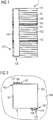
- the piezoelectric component 1 is a monolithic piezoelectric actuator in multilayer construction ( Figures 1 and 2 ).
- the piezoelectric actuator in multilayer construction has a stack 10 of piezoceramic layers 101 and electrode layers 102 arranged alternately one above the other.
- the piezoceramic layers have lead zirconate titanate.
- the electrode layers are formed by a palladium-silver alloy.
- porous safety layers 103 are installed. Due to the security layers, the stack can be subdivided into partial stacks.
- the security layer is of a ceramic nature.
- the security layer is formed by a metal layer.
- the security layer has an increased porosity compared to the rest of the stack. This leads to the fact that the security layer acts as a predetermined breaking point: With mechanical overloading of the stack, cracks occur preferentially in this security layer with the increased porosity. Thus, the control of cracking and the propagation of the crack is possible.
- metallizations 106 are arranged for electrically contacting the electrode layers of the stack. Via the two metallizations, the electrode layers can be applied alternately with different electrical potentials.
- wire brackets are soldered to the metallizations by means of an ironing method.
- a cover 104 made of a silicone-free polymer.
- the silicone-free polymer is a polyurethane in a first embodiment.
- the cover is made of polyimide.
- the conclusion is a sheath 108 made of a silicone. Between the outer electrode and the sheath, the cover is made of silicone-free polymer.
- a monolithic stack with piezoceramic layers, electrode layers and a porous security layer is first provided.
- ceramic green sheets are printed with metal, stacked one above the other to form a green sheet composite, debinded and sintered into a monolithic stack.
- the green sheets lead to the piezoceramic layers.
- the printed metal (metal layers) results in the electrode layers.
- an initial layer of the security layer is also integrated, from which the security layer is formed during the sintering process.
- the polymer or crosslinkable, silicone-free polymer is applied. This is done by spraying. After application, the crosslinking of the polymer is initiated in a suitable manner. It forms the cover of the silicone-free polymer.
- silicone is applied by injection molding and cured.
- the silicone acts as a support for the wires of the wire harp.
- an outer shape (contour) of the piezoelectric component is designed.
- the outer shape is adapted to an insert of the component.
- the plastic coating serves to round off the component.
- the monolithic stack including outer electrode and cover made of silicone-free polymer is inserted into a sleeve and a gap between the sleeve and the stack is sprayed with silicone.
Landscapes
- Engineering & Computer Science (AREA)
- Chemical & Material Sciences (AREA)
- Combustion & Propulsion (AREA)
- Mechanical Engineering (AREA)
- General Engineering & Computer Science (AREA)
- Manufacturing & Machinery (AREA)
- Fuel-Injection Apparatus (AREA)
Description
- Die Erfindung betrifft ein piezoelektrisches Bauteil mit einem monolithischen Stapel, aufweisend abwechselnd übereinander angeordnete Piezokeramikschichten und Elektrodenschichten, mindestens eine im Stapel angeordnete poröse Sicherheitsschicht zur Bildung eines Risses bei mechanischer Überlastung des Stapels, mindestens eine an einem seitlichen Oberflächenabschnitt angeordnete Außenelektrode zur elektrischen Kontaktierung der Elektrodenschichten und eine Kunststoffummantelung des Stapels zum Schutz des Stapels, wobei die Kunststoffummantelung Silikon aufweist. Neben dem Bauteil wird ein Verfahren zum Herstellen des Bauteils angegeben.
- Das piezoelektrische Bauteil ist ein keramischer Piezoaktor in monolithischer Vielschichtbauweise. Derartige Vielschichtaktoren weisen in einigen Ausführungsformen poröse, keramische oder metallische Sicherheitsschichten (Sicherheitsstrukturen) auf. Die porösen Sicherheitsschichten fungieren als Sollbruchstellen: Bei mechanischer Überlastung des Stapels des Piezoaktors kommt es vornehmlich in diesen Sicherheitsschichten zur Bildung von Rissen (Polungsrisse). Dadurch ist eine Lagedefinition und Führung der bei einer Polung oder im Betrieb entstehenden Polungsrisse möglich. Diese Sicherheitsschichten können von Keramikschichten oder von Elektrodenschichten (Innenelektroden) erhöhter Porosität gebildet werden.
- Zur elektrischen Kontaktierung sind die Innenelektroden abwechselnd an von einander elektrisch isolierte, seitliche O-berflächenabschnitte des Stapels geführt. An diesen Oberflächenabschnitten sind Metallisierungen (Außenmetallisierungen) angebracht. Über diese Metallisierungen, die als Bestandteil von Außenelektroden betrachtet werden können, sind die Innenelektroden alternierend elektrisch parallel geschaltet.
- Der Stapel des Piezoaktors ist mit einer Kunststoffummantelung aus Silikon versehen. Diese Kunststoffummantelung dient einer Passivierung des Stapels. Dies bedeutet: Durch die Kunststoffummantelung sind die bis an die seitlichen Oberflächen des Stapels reichenden Innenelektroden elektrisch isoliert und vor mechanischer Zerstörung geschützt.
- Beim Aufbringen des Silikons auf die Oberfläche des Stapels kann es zum Eindringen von Silikonbestandteilen in die poröse Sicherheitsschicht kommen. Infolge einer solchen Infiltration kann es insbesondere im Bereich der Außenmetallisierung und direkt darunter durch elektrische Entladungen oder mechanische Druckspannungen zur Zersetzung des Silikons und zur Ablagerung von Zersetzungsprodukten kommen. Dies kann eine mechanische Kerbwirkung im Riss entstehen lassen, die wiederum eine Schädigung der Sicherheitsschicht und deren Umgebung nach sich ziehen kann. Dies kann Längsrisse entlang einer Stapelrichtung des Stapels verursachen. Ein vorzeitiger Ausfall des Bauteils ist damit vorprogrammiert. Beispiele sind in
W02006/1334 US2003/107301 undDE 102004050803 . - Aufgabe der vorliegenden Erfindung ist es, ein Eindringen von Silikon in die poröse Sicherheitsschicht während einer Herstellung eines piezoelektrischen Bauteils mit einem monolithischen Stapel zu verhindern.
- Zur Lösung der Aufgabe wird ein piezoelektrisches Bauteil mit einem monolithischen Stapel angegeben, aufweisend abwechselnd übereinander angeordnete Piezokeramikschichten und Elektrodenschichten, mindestens eine im Stapel angeordnete poröse Sicherheitsschicht zur Bildung eines Risses bei mechanischer Überlastung des Stapels, mindestens eine an einem seitlichen Oberflächenabschnitt angeordnete Außenelektrode zur elektrischen Kontaktierung der Elektrodenschichten und eine Kunststoffummantelung des Stapels zum Schutz des Stapels, wobei die Kunststoffummantelung Silikon aufweist. Das piezoelektrische Bauteil ist dadurch gekennzeichnet, dass zwischen der Außenelektrode und der Kunststoffummantelung eine Beschichtung der Außenelektrode mit silikonfreiem Polymer angeordnet ist, die als Infiltrationsbarriere für Silikonbestandteile fungiert.
- Zur Lösung der Aufgabe wird auch ein Verfahren zum Herstellen des Bauteils mit folgenden Verfahrensschritten angegeben: a) Bereitstellen eines monolithischen Stapels mit abwechselnd übereinander angeordneten Elektrodenschichten und Piezokeramikschichten, mindestens einer im Stapel angeordneten porösen Sicherheitsschicht zur Bildung eines Risses bei mechanischer Überlastung des Stapels, und eine an einem seitlichen Oberflächenabschnitt des Stapels angebrachten Außenelektrode, b) Anordnen einer Beschichtung aus silikonfreiem Polymer auf der Außenelektrode und c) Anordnen der Kunststoffummantelung auf der Beschichtung.
- Die grundlegende Idee der Erfindung besteht darin, die Außenelektrode mit einem Silikon-freien Polymer abzudecken. Durch die Abdeckung ist gleichzeitig der unter der Außenelektrode befindliche Bereich einer porösen Sicherheitsschicht abgedeckt. Die Abdeckung fungiert als Infiltrationsbarriere für Silikonbestandteile.
- Silikon-frei bedeutet in diesem Zusammenhang, dass sehr geringe Anteile an Silikon von unter 1 Mol% und insbesondere von unter 0,1 Mol% vorhanden sind. Als Silikon-freies Polymer kommt eine Vielzahl von Kunststoffen in Frage. Vorzugsweise ist das silikonfreie Polymer zumindest ein aus der Gruppe Polyamid (PA), Polyester, Polyimid (PI), Polyetheretherketon (PEEK) und Polyurethan (PU) ausgewählter Kunststoff. Andere geeignete Materialien sind beispielsweise Polyester-Sulfon (PES), Polybutylenterephthalat (PBT), Polyethylenterephthalat (PET), Polycarbonat (PC) und Epoxidharz (EP).
- Die Außenelektrode weist verschiedene Bestandteile auf. So ist beispielsweise an einem seitlichen Oberflächenabschnitt des Stapels eine Einbrennmetallisierung (Außenmetallisierung) aufgebracht. Auf diese Außenmetallisierung wird beispielsweise mit Hilfe einer Lotbahn eine Drahtharfe angelötet. Dazu wird ein Bügellöt-(Thermodenlöt-)Prozess eingesetzt. Nach dem Anbringen der Außenelektrode erfolgt eine Abdeckung der Au-βenelektrode zumindest in dem Bereich, in dem die Außenelektrode an den Stapel angebracht ist (Kontaktierungsbereich). Vorteilhafterweise kann ein während eines Thermoden-Lötprozesses zum Schutz einer Thermode eingesetzte Karton®-Band direkt als Abdeckung verwendet werden.
- Nachdem die Abdeckung aus dem Silikon-freien Polymer aufgebracht ist, kann die Kunststoffummantelung aus Silikon aufgebracht werden. Dies erfolgt beispielsweise in einem Spritzgussverfahren.
- Das beschriebene piezoelektrische Bauteil mit dem Stapel in monolithischer Vielschichtbauweise wird vorzugsweise zum Ansteuern eines Ventils und insbesondere zum Ansteuern eines Einspritzventils einer Brennkraftmaschine verwendet.
- Zusammenfassend ergeben sich mit der Erfindung folgende wesentlichen Vorteile:
- Mit Hilfe der Abdeckung aus Silikon-freiem Kunststoff direkt auf der Außenmetallisierung verzögert sich während des Herstellungsverlaufs und im Betrieb des Piezoaktors ein Eindringen von flüssigem Material in den Bereich der Sicherheitsschicht und direkt unter der Außenmetallisierung.
- Ebenso wird nach der Polung des Stapels beziehungsweise dem Auftreten von Polungsrissen in einer Sicherheitsschicht des Stapels das Eindringen der Materialien vermieden.
- Beides führt dazu, dass ungewollte mechanische Spannungen und Querriss-Initiierungen im Bereich einer Sicherheitsschicht vermieden werden. Dies führt zum Funktionserhalt des piezoelektrischen Bauteils, insbesondere bei hohen elektrischen, mechanischen und thermischen Belastungen.
- Anhand eines Ausführungsbeispiels und der dazugehörigen Figuren wird die Erfindung im Folgenden näher beschrieben. Die Figuren sind schematisch und stellen keine maßstabsgetreuen Abbildungen dar.
- Figur 1
- zeigt einen monolithischen Stapel eines piezoelektrischen Bauteils von der Seite.
- Figur 2
- zeigt einen Schnitt durch den Stapel auf der Höhe einer Sicherheitsschicht.
- Das piezoelektrische Bauteil 1 ist ein monolithischer Piezoaktor in Vielschichtbauweise (
Figuren 1 und 2 ). Der Piezoaktor in Vielschichtbauweise weist einen Stapel 10 aus abwechselnd übereinander angeordneten Piezokeramikschichten 101 und Elektrodenschichten 102 auf. Die Piezokeramikschichten weisen Bleizirkonattitanat auf. Die Elektrodenschichten werden von einer Palladium-Silber-Legierung gebildet. Im Stapel sind poröse Sicherheitsschichten 103 eingebaut. Durch die Sicherheitsschichten ist der Stapel in Teilstapel unterteilbar. - Gemäß einer ersten Ausführungsform ist die Sicherheitsschicht keramischer Natur. In einer dazu alternativen Ausführungsform wird die Sicherheitsschicht von einer Metallschicht gebildet. Bei beiden Ausführungsformen weist die Sicherheitsschicht eine im Vergleich zum Rest des Stapels erhöhte Porosität auf. Dies führt dazu, dass die Sicherheitsschicht als Sollbruchstelle fungiert: Bei mechanischer Überlastung des Stapels treten bevorzugt in dieser Sicherheitsschicht mit der erhöhten Porosität Risse auf. Damit ist die Steuerung der Rissbildung und der Ausbreitung des Risses möglich.
- An seitlichen Oberflächenabschnitten 107 des Stapels sind Metallisierungen 106 zur elektrischen Kontaktierung der Elektrodenschichten des Stapels angeordnet. Über die beiden Metallisierungen können die Elektrodenschichten alternierend mit unterschiedlichen elektrischen Potenzialen beaufschlagt werden. Dazu sind nicht gezeigte Drahtharfen an die Metallisierungen mit Hilfe eines Bügellöt-Verfahrens gelötet.
- Über den Metallisierungen befindet sich eine Abdeckung 104 aus einem Silikon-freien Polymer. Das Silikon-freie Polymer ist in einer ersten Ausführungsform ein Polyurethan. In einer alternativen Ausführungsform ist die Abdeckung aus Polyimid.
- Den Abschluss bildet eine Ummantelung 108 aus einem Silikon. Zwischen der Außenelektrode und der Ummantelung ist die Abdeckung aus Silikon-freiem Polymer angeordnet.
- Zum Herstellen des piezoelektrischen Bauteils wird zunächst ein monolithischer Stapel mit Piezokeramikschichten, Elektrodenschichten und poröser Sicherheitsschicht bereitgestellt. Dazu werden keramische Grünfolien mit Metall bedruckt, übereinander zu einem Grünfolienverbund gestapelt, entbindert und zum monolithischen Stapel gesintert. Die Grünfolien führen zu den Piezokeramikschichten. Aus dem aufgedruckten Metall (Metallschichten) resultieren die Elektrodenschichten. Im Grünfolienverbund wird zudem eine Ausgangsschicht der Sicherheitsschicht integriert, aus der während des Sintervorgangs die Sicherheitsschicht gebildet wird.
- Anschließend werden an den seitlichen Oberflächenabschnitten des Stapels Außenelektroden angebracht. Dazu werden zunächst Metallisierungen aufgebracht. An die Metallisierung werden, wie bereits geschildert, Drahtharfen angelötet.
- Nach dem Anlöten der Drahtharfen wird das Polymer bzw. vernetzbares, Silikon-freies Polymer aufgetragen. Dies erfolgt durch Spritzen. Nach dem Auftragen wird die Vernetzung des Polymers in geeigneter Weise initiiert. Es bildet sich die Abdeckung aus dem Silikon-freien Polymer.
- Nach dem Herstellen der Abdeckung wird Silikon in einem Spritzgussverfahren aufgetragen und ausgehärtet. Das Silikon fungiert als Stütze für die Drähte der Drahtharfe. Darüber hinaus wird eine äußere Form (Kontur) des piezoelektrischen Bauteils gestaltet. Die äußere Form ist an einen Einsatz des Bauteils angepasst. Beispielsweise dient die Kunststoffummantelung einer Abrundung des Bauteils. In einer dazu alternativen Ausführungsform wird der monolithische Stapel inklusive Außenelektrode und Abdeckung aus Silikon-freiem Polymer in eine Hülse gesteckt und ein Zwischenraum zwischen der Hülse und dem Stapel mit Silikon ausgespritzt.
Claims (6)
- Piezoelektrisches Bauteil (1) mit einem monolithischen Stapel (10), aufweisend- abwechselnd übereinander angeordnete Piezokeramikschichten (101) und Elektrodenschichten (102),- mindestens eine im Stapel (10) angeordnete poröse Sicherheitsschicht (103) zur Bildung eines Risses bei mechanischer Überlastung des Stapels (10),- mindestens eine an einem seitlichen Oberflächenabschnitt (107) angeordnete Außenelektrode (106) zur elektrischen Kontaktierung der Elektrodenschichten (102) und- eine Kunststoffummantelung (108) des Stapels (10) zum Schutz des Stapels-(10), wobei die Kunststoffummantelung (108) Silikon aufweist, wobei- zwischen der Außenelektrode (106) und der Kunststoffummantelung (108) eine die Außenelektrode abdeckende, als Infiltrationsbarriere für Silikonbestandteile fungierende Beschichtung (104) der Außenelektrode (106) mit Silikon freiem Polymer angeordnet ist.
- Bauteil nach Anspruch 1, wobei die Außenelektrode eine Metallisierungsbahn und/oder eine Lotbahn aufweist, die durch die Beschichtung abgedeckt ist.
- Bauteil nach Anspruch 1 oder 2, wobei das Silikon-freie Polymer zumindest ein aus der Gruppe Polyamid, Polyester, Polyimid, Polyetheretherketon, Polyurethan und Epoxidharz ausgewählter Kunststoff ist.
- Verfahren zum Herstellen eines Bauteils nach einem der Ansprüche 1 bis 3 mit folgenden Verfahrensschritten:a) Bereitstellen eines monolithischen Stapels mit abwechselnd übereinander angeordneten Elektrodenschichten und Piezokeramikschichten, mindestens einer im Stapel angeordneten porösen Sicherheitsschicht zur Bildung eines Risses bei mechanischer Überlastung des Stapels, und einer an einem seitlichen Oberflächenabschnitt des Stapels angebrachten Außenelektrode,b) Anordnen einer die Außenelektrode abdeckende Beschichtung aus Silikon freiem Polymer auf der Außenelektrode undc) Anordnen der Kunststoffummantelung mit Silikon auf der Beschichtung.
- Verfahren nach Anspruch 4, wobei zum Anordnen der Beschichtung nicht vernetztes oder teilvernetztes Ausgangsmaterial des Polymers durch ein aus der Gruppe Pinseln, Siebdruck und/oder Spritzen ausgewähltes Verfahren auf die Außenmetallisierung aufgetragen und anschließend vernetzt wird.
- Verwendung eines piezoelektrischen Bauteils nach einem der Ansprüche 1 bis 3 zum Ansteuern eines Ventils und insbesondere eines Einspritzventils einer Brennkraftmaschine.
Applications Claiming Priority (2)
| Application Number | Priority Date | Filing Date | Title |
|---|---|---|---|
| DE102007015457A DE102007015457B4 (de) | 2007-03-30 | 2007-03-30 | Piezoelektrisches Bauteil mit Sicherheitsschicht, Verfahren zu dessen Herstellung und Verwendung |
| PCT/EP2008/053550 WO2008119704A1 (de) | 2007-03-30 | 2008-03-26 | Piezoelektrisches bauteil mit sicherheitsschicht und verfahren zu dessen herstellung |
Publications (2)
| Publication Number | Publication Date |
|---|---|
| EP2132796A1 EP2132796A1 (de) | 2009-12-16 |
| EP2132796B1 true EP2132796B1 (de) | 2012-05-02 |
Family
ID=39409987
Family Applications (1)
| Application Number | Title | Priority Date | Filing Date |
|---|---|---|---|
| EP08718222A Not-in-force EP2132796B1 (de) | 2007-03-30 | 2008-03-26 | Piezoelektrisches bauteil mit sicherheitsschicht und verfahren zu dessen herstellung |
Country Status (6)
| Country | Link |
|---|---|
| US (1) | US8492955B2 (de) |
| EP (1) | EP2132796B1 (de) |
| JP (1) | JP5582785B2 (de) |
| AT (1) | ATE556438T1 (de) |
| DE (1) | DE102007015457B4 (de) |
| WO (1) | WO2008119704A1 (de) |
Families Citing this family (7)
| Publication number | Priority date | Publication date | Assignee | Title |
|---|---|---|---|---|
| DE102006049892A1 (de) * | 2006-10-23 | 2008-05-08 | Siemens Ag | Monolithischer Piezoaktor mit Übergangsbereich und Sicherheitsschicht sowie Verwendung des Piezoaktors |
| JP5090466B2 (ja) * | 2007-11-28 | 2012-12-05 | 京セラ株式会社 | 積層型圧電素子、これを備えた噴射装置及び燃料噴射システム |
| CN102473834A (zh) * | 2009-07-28 | 2012-05-23 | 京瓷株式会社 | 层叠型压电元件及使用该层叠型压电元件的喷射装置以及燃料喷射系统 |
| DE102010047302B3 (de) * | 2010-10-01 | 2012-03-29 | Epcos Ag | Piezoelektrisches Vielschichtbauelement und Verfahren zu dessen Herstellung |
| DE102010050266A1 (de) * | 2010-11-02 | 2012-05-03 | Epcos Ag | Aktoreinheit, Verfahren zur Fertigung einer Aktoreinheit und Hülse zur Aufnahme eines Piezoaktors |
| KR101536973B1 (ko) * | 2014-01-28 | 2015-07-22 | 한국기계연구원 | 단결정 압전 섬유 포함 복합체 및 이를 포함하는 자기전기 복합재료 적층체 |
| KR101715767B1 (ko) * | 2015-02-10 | 2017-03-14 | 범진전자 주식회사 | 압전 스피커용 압전 소자 |
Family Cites Families (25)
| Publication number | Priority date | Publication date | Assignee | Title |
|---|---|---|---|---|
| JPH0666483B2 (ja) * | 1987-11-24 | 1994-08-24 | 日本電気株式会社 | 電歪効果素子 |
| EP1160885B1 (de) * | 2000-05-31 | 2010-08-18 | Denso Corporation | Piezoelektrisches Bauelement für eine Einspritzvorrichtung |
| JP2002203998A (ja) * | 2000-12-28 | 2002-07-19 | Denso Corp | 圧電体素子及びその製造方法 |
| JP3900918B2 (ja) | 2001-12-10 | 2007-04-04 | 株式会社デンソー | 圧電アクチュエータ |
| DE10327902A1 (de) * | 2002-07-19 | 2004-06-24 | Ceramtec Ag Innovative Ceramic Engineering | Außenelektrode an einem piezokeramischen Vielschichtaktor |
| DE10307825A1 (de) | 2003-02-24 | 2004-09-09 | Epcos Ag | Elektrisches Vielschichtbauelement und Schichtstapel |
| JP4093188B2 (ja) * | 2003-05-27 | 2008-06-04 | 株式会社村田製作所 | 積層セラミック電子部品とその実装構造および実装方法 |
| WO2005029602A1 (ja) * | 2003-09-24 | 2005-03-31 | Kyocera Corporation | 積層型圧電素子 |
| DE602004024104D1 (de) * | 2003-09-25 | 2009-12-24 | Kyocera Corp | Mehrschichtiges piezoelektrisches bauelement |
| DE102004005226A1 (de) * | 2004-02-03 | 2005-08-18 | Robert Bosch Gmbh | Piezoaktor mit einer Isolierschicht |
| JP4925825B2 (ja) | 2004-06-24 | 2012-05-09 | 京セラ株式会社 | 積層型電子部品及びこれを用いた噴射装置 |
| DE102004031402A1 (de) * | 2004-06-29 | 2006-02-09 | Siemens Ag | Piezoelektrisches Bauteil mit Sollbruchstelle, Verfahren zum Herstellen des Bauteils und Verwendung des Bauteils |
| JP4706209B2 (ja) * | 2004-08-30 | 2011-06-22 | 株式会社デンソー | 積層型圧電体素子及びその製造方法並びに導電性接着剤 |
| DE102004050803A1 (de) * | 2004-10-19 | 2006-04-20 | Robert Bosch Gmbh | Piezoaktor |
| JP2006165193A (ja) * | 2004-12-06 | 2006-06-22 | Denso Corp | 中空積層型圧電素子及びその製造方法 |
| JP4876467B2 (ja) * | 2004-12-06 | 2012-02-15 | 株式会社デンソー | 積層型圧電素子 |
| DE102005026717B4 (de) * | 2005-06-09 | 2016-09-15 | Epcos Ag | Piezoelektrisches Vielschichtbauelement |
| EP1942533B1 (de) * | 2005-10-28 | 2013-05-01 | Kyocera Corporation | Geschichtetes piezoelektrisches element und injektionsvorrichtung damit |
| JP2007157849A (ja) * | 2005-12-01 | 2007-06-21 | Denso Corp | 積層型圧電素子の製造方法 |
| JP2009527118A (ja) * | 2006-02-14 | 2009-07-23 | デルファイ・テクノロジーズ・インコーポレーテッド | 圧電装置のバリヤ被覆 |
| WO2008047460A1 (en) * | 2006-10-20 | 2008-04-24 | Kyocera Corporation | Piezoelectric actuator unit and method for manufacturing the same |
| US8212451B2 (en) * | 2006-10-31 | 2012-07-03 | Kyocera Corporation | Multi-layer piezoelectric element having a plurality of junction sections and injection apparatus employing the same |
| DE102006062076A1 (de) * | 2006-12-29 | 2008-07-10 | Siemens Ag | Piezokeramischer Vielschichtaktor und Verfahren zu seiner Herstellung |
| DE102007037500A1 (de) * | 2007-05-11 | 2008-11-13 | Epcos Ag | Piezoelektrisches Vielschichtbauelement |
| JP5176775B2 (ja) * | 2008-06-02 | 2013-04-03 | 株式会社村田製作所 | セラミック電子部品及びその製造方法 |
-
2007
- 2007-03-30 DE DE102007015457A patent/DE102007015457B4/de not_active Expired - Fee Related
-
2008
- 2008-03-26 JP JP2009553167A patent/JP5582785B2/ja not_active Expired - Fee Related
- 2008-03-26 US US12/593,319 patent/US8492955B2/en not_active Expired - Fee Related
- 2008-03-26 EP EP08718222A patent/EP2132796B1/de not_active Not-in-force
- 2008-03-26 AT AT08718222T patent/ATE556438T1/de active
- 2008-03-26 WO PCT/EP2008/053550 patent/WO2008119704A1/de not_active Ceased
Also Published As
| Publication number | Publication date |
|---|---|
| ATE556438T1 (de) | 2012-05-15 |
| DE102007015457B4 (de) | 2009-07-09 |
| EP2132796A1 (de) | 2009-12-16 |
| JP2010521071A (ja) | 2010-06-17 |
| US20100026144A1 (en) | 2010-02-04 |
| US8492955B2 (en) | 2013-07-23 |
| WO2008119704A1 (de) | 2008-10-09 |
| JP5582785B2 (ja) | 2014-09-03 |
| DE102007015457A1 (de) | 2008-10-02 |
Similar Documents
| Publication | Publication Date | Title |
|---|---|---|
| EP2132796B1 (de) | Piezoelektrisches bauteil mit sicherheitsschicht und verfahren zu dessen herstellung | |
| EP2126991B1 (de) | Piezokeramischer vielschichtaktor und verfahren zu seiner herstellung | |
| EP1908131A1 (de) | Verfahren zum herstellen eines monolithischen piezoaktors mit teilstapeln, monolithischer piezoaktor mit teilstapeln und verwendung des piezoaktors | |
| EP2345095B1 (de) | Piezoaktor in Vielschichtbauweise und Verfahren zur Befestigung einer Aussenelektrode bei einem Piezoaktor | |
| EP2140508B1 (de) | Piezoelektrisches bauteil mit sicherheitsschicht und infiltrationsbarriere und verfahren zu dessen herstellung | |
| DE102012207276B4 (de) | Vollaktiver Piezostack mit Passivierung | |
| EP2319102A1 (de) | Piezoaktor mit sollbruchschicht | |
| WO2007141133A2 (de) | Piezoelektrischer aktor | |
| DE102009017434A1 (de) | Elektronisches Bauelement und Verfahren zum elektrischen Kontaktieren eines elektronischen Bauelements als Stapel | |
| EP2798679B1 (de) | Piezostack mit passivierung und verfahren zur passivierung eines piezostacks | |
| EP2417643B1 (de) | Piezoelektrischer aktor und verfahren zur herstellung eines piezoelektrischen aktors | |
| DE102006001656A1 (de) | Piezoaktor und Verfahren zur Herstellung desselben | |
| EP2071645B1 (de) | Piezoaktor mit einem Multilagenaufbau von Piezoelementen | |
| EP1973176A2 (de) | Verfahren und Vorrichtung zur Herstellung eines Piezoaktormoduls mit einem umhüllten Piezoaktor und ein Piezoaktormodul | |
| EP3056724A1 (de) | Kraftstoffinjektor und verfahren zur herstellung eines piezoelements für einen kraftstoffinjektor | |
| EP1808906A2 (de) | Piezoaktor mit verbesserter Sicherheit gegen Kurzschlüsse | |
| DE102006024958A1 (de) | Piezoaktor mit einer Sicherheitsschicht, die ein Phasenübergangsmaterial aufweist, Verfahren zum Herstellen des Piezoaktors und Verwendung des Piezoaktors | |
| EP1767770B1 (de) | Piezoelektrischer Aktor | |
| WO2012080206A1 (de) | Elektroden-trägerfolie, insbesondere zur herstellung von piezoelektrischen bauelementen, und verfahren zur herstellung eines piezoelektrischen bauelements | |
| DE102008040772A1 (de) | Piezoaktor mit passiven Bereichen am Kopf und/oder am Fuß | |
| WO2011009668A1 (de) | Piezoaktor mit einem mehrlagenaufbau und ein verfahren zu dessen herstellung | |
| DE102011087183A1 (de) | Piezoelektrisches Vielschichtbauteil |
Legal Events
| Date | Code | Title | Description |
|---|---|---|---|
| PUAI | Public reference made under article 153(3) epc to a published international application that has entered the european phase |
Free format text: ORIGINAL CODE: 0009012 |
|
| 17P | Request for examination filed |
Effective date: 20090706 |
|
| AK | Designated contracting states |
Kind code of ref document: A1 Designated state(s): AT BE BG CH CY CZ DE DK EE ES FI FR GB GR HR HU IE IS IT LI LT LU LV MC MT NL NO PL PT RO SE SI SK TR |
|
| 17Q | First examination report despatched |
Effective date: 20100305 |
|
| DAX | Request for extension of the european patent (deleted) | ||
| GRAP | Despatch of communication of intention to grant a patent |
Free format text: ORIGINAL CODE: EPIDOSNIGR1 |
|
| RIC1 | Information provided on ipc code assigned before grant |
Ipc: H01L 41/053 20060101ALI20110929BHEP Ipc: H01L 41/083 20060101AFI20110929BHEP Ipc: H01L 41/04 20060101ALI20110929BHEP |
|
| GRAS | Grant fee paid |
Free format text: ORIGINAL CODE: EPIDOSNIGR3 |
|
| GRAA | (expected) grant |
Free format text: ORIGINAL CODE: 0009210 |
|
| AK | Designated contracting states |
Kind code of ref document: B1 Designated state(s): AT BE BG CH CY CZ DE DK EE ES FI FR GB GR HR HU IE IS IT LI LT LU LV MC MT NL NO PL PT RO SE SI SK TR |
|
| REG | Reference to a national code |
Ref country code: GB Ref legal event code: FG4D Free format text: NOT ENGLISH |
|
| REG | Reference to a national code |
Ref country code: AT Ref legal event code: REF Ref document number: 556438 Country of ref document: AT Kind code of ref document: T Effective date: 20120515 Ref country code: CH Ref legal event code: EP |
|
| REG | Reference to a national code |
Ref country code: IE Ref legal event code: FG4D Free format text: LANGUAGE OF EP DOCUMENT: GERMAN |
|
| REG | Reference to a national code |
Ref country code: DE Ref legal event code: R096 Ref document number: 502008007131 Country of ref document: DE Effective date: 20120628 |
|
| REG | Reference to a national code |
Ref country code: NL Ref legal event code: VDEP Effective date: 20120502 |
|
| REG | Reference to a national code |
Ref country code: LT Ref legal event code: MG4D Effective date: 20120516 |
|
| PG25 | Lapsed in a contracting state [announced via postgrant information from national office to epo] |
Ref country code: FI Free format text: LAPSE BECAUSE OF FAILURE TO SUBMIT A TRANSLATION OF THE DESCRIPTION OR TO PAY THE FEE WITHIN THE PRESCRIBED TIME-LIMIT Effective date: 20120502 Ref country code: SE Free format text: LAPSE BECAUSE OF FAILURE TO SUBMIT A TRANSLATION OF THE DESCRIPTION OR TO PAY THE FEE WITHIN THE PRESCRIBED TIME-LIMIT Effective date: 20120502 Ref country code: IS Free format text: LAPSE BECAUSE OF FAILURE TO SUBMIT A TRANSLATION OF THE DESCRIPTION OR TO PAY THE FEE WITHIN THE PRESCRIBED TIME-LIMIT Effective date: 20120902 Ref country code: PL Free format text: LAPSE BECAUSE OF FAILURE TO SUBMIT A TRANSLATION OF THE DESCRIPTION OR TO PAY THE FEE WITHIN THE PRESCRIBED TIME-LIMIT Effective date: 20120502 Ref country code: CY Free format text: LAPSE BECAUSE OF FAILURE TO SUBMIT A TRANSLATION OF THE DESCRIPTION OR TO PAY THE FEE WITHIN THE PRESCRIBED TIME-LIMIT Effective date: 20120502 Ref country code: LT Free format text: LAPSE BECAUSE OF FAILURE TO SUBMIT A TRANSLATION OF THE DESCRIPTION OR TO PAY THE FEE WITHIN THE PRESCRIBED TIME-LIMIT Effective date: 20120502 Ref country code: NO Free format text: LAPSE BECAUSE OF FAILURE TO SUBMIT A TRANSLATION OF THE DESCRIPTION OR TO PAY THE FEE WITHIN THE PRESCRIBED TIME-LIMIT Effective date: 20120802 |
|
| PG25 | Lapsed in a contracting state [announced via postgrant information from national office to epo] |
Ref country code: PT Free format text: LAPSE BECAUSE OF FAILURE TO SUBMIT A TRANSLATION OF THE DESCRIPTION OR TO PAY THE FEE WITHIN THE PRESCRIBED TIME-LIMIT Effective date: 20120903 Ref country code: GR Free format text: LAPSE BECAUSE OF FAILURE TO SUBMIT A TRANSLATION OF THE DESCRIPTION OR TO PAY THE FEE WITHIN THE PRESCRIBED TIME-LIMIT Effective date: 20120803 Ref country code: HR Free format text: LAPSE BECAUSE OF FAILURE TO SUBMIT A TRANSLATION OF THE DESCRIPTION OR TO PAY THE FEE WITHIN THE PRESCRIBED TIME-LIMIT Effective date: 20120502 Ref country code: SI Free format text: LAPSE BECAUSE OF FAILURE TO SUBMIT A TRANSLATION OF THE DESCRIPTION OR TO PAY THE FEE WITHIN THE PRESCRIBED TIME-LIMIT Effective date: 20120502 Ref country code: LV Free format text: LAPSE BECAUSE OF FAILURE TO SUBMIT A TRANSLATION OF THE DESCRIPTION OR TO PAY THE FEE WITHIN THE PRESCRIBED TIME-LIMIT Effective date: 20120502 |
|
| PG25 | Lapsed in a contracting state [announced via postgrant information from national office to epo] |
Ref country code: CZ Free format text: LAPSE BECAUSE OF FAILURE TO SUBMIT A TRANSLATION OF THE DESCRIPTION OR TO PAY THE FEE WITHIN THE PRESCRIBED TIME-LIMIT Effective date: 20120502 Ref country code: DK Free format text: LAPSE BECAUSE OF FAILURE TO SUBMIT A TRANSLATION OF THE DESCRIPTION OR TO PAY THE FEE WITHIN THE PRESCRIBED TIME-LIMIT Effective date: 20120502 Ref country code: SK Free format text: LAPSE BECAUSE OF FAILURE TO SUBMIT A TRANSLATION OF THE DESCRIPTION OR TO PAY THE FEE WITHIN THE PRESCRIBED TIME-LIMIT Effective date: 20120502 Ref country code: RO Free format text: LAPSE BECAUSE OF FAILURE TO SUBMIT A TRANSLATION OF THE DESCRIPTION OR TO PAY THE FEE WITHIN THE PRESCRIBED TIME-LIMIT Effective date: 20120502 Ref country code: EE Free format text: LAPSE BECAUSE OF FAILURE TO SUBMIT A TRANSLATION OF THE DESCRIPTION OR TO PAY THE FEE WITHIN THE PRESCRIBED TIME-LIMIT Effective date: 20120502 Ref country code: NL Free format text: LAPSE BECAUSE OF FAILURE TO SUBMIT A TRANSLATION OF THE DESCRIPTION OR TO PAY THE FEE WITHIN THE PRESCRIBED TIME-LIMIT Effective date: 20120502 |
|
| PG25 | Lapsed in a contracting state [announced via postgrant information from national office to epo] |
Ref country code: IT Free format text: LAPSE BECAUSE OF FAILURE TO SUBMIT A TRANSLATION OF THE DESCRIPTION OR TO PAY THE FEE WITHIN THE PRESCRIBED TIME-LIMIT Effective date: 20120502 |
|
| PLBE | No opposition filed within time limit |
Free format text: ORIGINAL CODE: 0009261 |
|
| STAA | Information on the status of an ep patent application or granted ep patent |
Free format text: STATUS: NO OPPOSITION FILED WITHIN TIME LIMIT |
|
| RAP2 | Party data changed (patent owner data changed or rights of a patent transferred) |
Owner name: SIEMENS AKTIENGESELLSCHAFT |
|
| 26N | No opposition filed |
Effective date: 20130205 |
|
| PG25 | Lapsed in a contracting state [announced via postgrant information from national office to epo] |
Ref country code: ES Free format text: LAPSE BECAUSE OF FAILURE TO SUBMIT A TRANSLATION OF THE DESCRIPTION OR TO PAY THE FEE WITHIN THE PRESCRIBED TIME-LIMIT Effective date: 20120813 |
|
| REG | Reference to a national code |
Ref country code: DE Ref legal event code: R097 Ref document number: 502008007131 Country of ref document: DE Effective date: 20130205 |
|
| PG25 | Lapsed in a contracting state [announced via postgrant information from national office to epo] |
Ref country code: BG Free format text: LAPSE BECAUSE OF FAILURE TO SUBMIT A TRANSLATION OF THE DESCRIPTION OR TO PAY THE FEE WITHIN THE PRESCRIBED TIME-LIMIT Effective date: 20120802 |
|
| BERE | Be: lapsed |
Owner name: SIEMENS A.G. Effective date: 20130331 |
|
| PG25 | Lapsed in a contracting state [announced via postgrant information from national office to epo] |
Ref country code: MC Free format text: LAPSE BECAUSE OF NON-PAYMENT OF DUE FEES Effective date: 20130331 |
|
| REG | Reference to a national code |
Ref country code: CH Ref legal event code: PL |
|
| REG | Reference to a national code |
Ref country code: IE Ref legal event code: MM4A |
|
| PG25 | Lapsed in a contracting state [announced via postgrant information from national office to epo] |
Ref country code: LI Free format text: LAPSE BECAUSE OF NON-PAYMENT OF DUE FEES Effective date: 20130331 Ref country code: IE Free format text: LAPSE BECAUSE OF NON-PAYMENT OF DUE FEES Effective date: 20130326 Ref country code: CH Free format text: LAPSE BECAUSE OF NON-PAYMENT OF DUE FEES Effective date: 20130331 Ref country code: BE Free format text: LAPSE BECAUSE OF NON-PAYMENT OF DUE FEES Effective date: 20130331 |
|
| REG | Reference to a national code |
Ref country code: AT Ref legal event code: MM01 Ref document number: 556438 Country of ref document: AT Kind code of ref document: T Effective date: 20130326 |
|
| PG25 | Lapsed in a contracting state [announced via postgrant information from national office to epo] |
Ref country code: MT Free format text: LAPSE BECAUSE OF FAILURE TO SUBMIT A TRANSLATION OF THE DESCRIPTION OR TO PAY THE FEE WITHIN THE PRESCRIBED TIME-LIMIT Effective date: 20120502 |
|
| PG25 | Lapsed in a contracting state [announced via postgrant information from national office to epo] |
Ref country code: AT Free format text: LAPSE BECAUSE OF NON-PAYMENT OF DUE FEES Effective date: 20130326 |
|
| PG25 | Lapsed in a contracting state [announced via postgrant information from national office to epo] |
Ref country code: TR Free format text: LAPSE BECAUSE OF FAILURE TO SUBMIT A TRANSLATION OF THE DESCRIPTION OR TO PAY THE FEE WITHIN THE PRESCRIBED TIME-LIMIT Effective date: 20120502 |
|
| PG25 | Lapsed in a contracting state [announced via postgrant information from national office to epo] |
Ref country code: HU Free format text: LAPSE BECAUSE OF FAILURE TO SUBMIT A TRANSLATION OF THE DESCRIPTION OR TO PAY THE FEE WITHIN THE PRESCRIBED TIME-LIMIT; INVALID AB INITIO Effective date: 20080326 Ref country code: LU Free format text: LAPSE BECAUSE OF NON-PAYMENT OF DUE FEES Effective date: 20130326 |
|
| REG | Reference to a national code |
Ref country code: FR Ref legal event code: PLFP Year of fee payment: 9 |
|
| REG | Reference to a national code |
Ref country code: FR Ref legal event code: PLFP Year of fee payment: 9 |
|
| REG | Reference to a national code |
Ref country code: DE Ref legal event code: R081 Ref document number: 502008007131 Country of ref document: DE Owner name: VITESCO TECHNOLOGIES GMBH, DE Free format text: FORMER OWNER: SIEMENS AKTIENGESELLSCHAFT, 80333 MUENCHEN, DE Ref country code: DE Ref legal event code: R081 Ref document number: 502008007131 Country of ref document: DE Owner name: CONTINENTAL AUTOMOTIVE GMBH, DE Free format text: FORMER OWNER: SIEMENS AKTIENGESELLSCHAFT, 80333 MUENCHEN, DE |
|
| REG | Reference to a national code |
Ref country code: GB Ref legal event code: 732E Free format text: REGISTERED BETWEEN 20160901 AND 20160907 |
|
| REG | Reference to a national code |
Ref country code: FR Ref legal event code: TP Owner name: CONTINENTAL AUTOMOTIVE GMBH, DE Effective date: 20160909 |
|
| REG | Reference to a national code |
Ref country code: FR Ref legal event code: PLFP Year of fee payment: 10 |
|
| REG | Reference to a national code |
Ref country code: FR Ref legal event code: PLFP Year of fee payment: 11 |
|
| PGFP | Annual fee paid to national office [announced via postgrant information from national office to epo] |
Ref country code: GB Payment date: 20180321 Year of fee payment: 11 |
|
| PGFP | Annual fee paid to national office [announced via postgrant information from national office to epo] |
Ref country code: FR Payment date: 20180330 Year of fee payment: 11 |
|
| PGFP | Annual fee paid to national office [announced via postgrant information from national office to epo] |
Ref country code: DE Payment date: 20180331 Year of fee payment: 11 |
|
| REG | Reference to a national code |
Ref country code: DE Ref legal event code: R119 Ref document number: 502008007131 Country of ref document: DE |
|
| GBPC | Gb: european patent ceased through non-payment of renewal fee |
Effective date: 20190326 |
|
| PG25 | Lapsed in a contracting state [announced via postgrant information from national office to epo] |
Ref country code: GB Free format text: LAPSE BECAUSE OF NON-PAYMENT OF DUE FEES Effective date: 20190326 Ref country code: DE Free format text: LAPSE BECAUSE OF NON-PAYMENT OF DUE FEES Effective date: 20191001 |
|
| PG25 | Lapsed in a contracting state [announced via postgrant information from national office to epo] |
Ref country code: FR Free format text: LAPSE BECAUSE OF NON-PAYMENT OF DUE FEES Effective date: 20190331 |
|
| REG | Reference to a national code |
Ref country code: DE Ref legal event code: R081 Ref document number: 502008007131 Country of ref document: DE Owner name: VITESCO TECHNOLOGIES GMBH, DE Free format text: FORMER OWNER: CONTINENTAL AUTOMOTIVE GMBH, 30165 HANNOVER, DE |