EP2132805B1 - Stromspeichervorrichtung - Google Patents
Stromspeichervorrichtung Download PDFInfo
- Publication number
- EP2132805B1 EP2132805B1 EP20080719272 EP08719272A EP2132805B1 EP 2132805 B1 EP2132805 B1 EP 2132805B1 EP 20080719272 EP20080719272 EP 20080719272 EP 08719272 A EP08719272 A EP 08719272A EP 2132805 B1 EP2132805 B1 EP 2132805B1
- Authority
- EP
- European Patent Office
- Prior art keywords
- electricity storage
- case
- gas
- storage unit
- storage device
- Prior art date
- Legal status (The legal status is an assumption and is not a legal conclusion. Google has not performed a legal analysis and makes no representation as to the accuracy of the status listed.)
- Not-in-force
Links
- 230000005611 electricity Effects 0.000 title claims abstract description 72
- 239000002826 coolant Substances 0.000 claims abstract description 36
- 238000001816 cooling Methods 0.000 claims abstract description 4
- 238000007599 discharging Methods 0.000 claims description 6
- 230000007246 mechanism Effects 0.000 claims description 6
- 230000002093 peripheral effect Effects 0.000 claims description 5
- 239000007789 gas Substances 0.000 description 68
- 230000017525 heat dissipation Effects 0.000 description 6
- 238000004519 manufacturing process Methods 0.000 description 4
- 239000000463 material Substances 0.000 description 4
- 230000008859 change Effects 0.000 description 3
- 239000007788 liquid Substances 0.000 description 3
- 230000004048 modification Effects 0.000 description 3
- 238000012986 modification Methods 0.000 description 3
- XEEYBQQBJWHFJM-UHFFFAOYSA-N Iron Chemical compound [Fe] XEEYBQQBJWHFJM-UHFFFAOYSA-N 0.000 description 2
- 230000007797 corrosion Effects 0.000 description 2
- 238000005260 corrosion Methods 0.000 description 2
- 230000005484 gravity Effects 0.000 description 2
- 238000003756 stirring Methods 0.000 description 2
- RYGMFSIKBFXOCR-UHFFFAOYSA-N Copper Chemical compound [Cu] RYGMFSIKBFXOCR-UHFFFAOYSA-N 0.000 description 1
- HBBGRARXTFLTSG-UHFFFAOYSA-N Lithium ion Chemical compound [Li+] HBBGRARXTFLTSG-UHFFFAOYSA-N 0.000 description 1
- 230000002159 abnormal effect Effects 0.000 description 1
- 230000005856 abnormality Effects 0.000 description 1
- 239000003990 capacitor Substances 0.000 description 1
- 238000010276 construction Methods 0.000 description 1
- 229910052802 copper Inorganic materials 0.000 description 1
- 239000010949 copper Substances 0.000 description 1
- 238000001514 detection method Methods 0.000 description 1
- 238000010586 diagram Methods 0.000 description 1
- 238000005868 electrolysis reaction Methods 0.000 description 1
- 239000008151 electrolyte solution Substances 0.000 description 1
- 239000001257 hydrogen Substances 0.000 description 1
- 229910052739 hydrogen Inorganic materials 0.000 description 1
- 229910052742 iron Inorganic materials 0.000 description 1
- 229910001416 lithium ion Inorganic materials 0.000 description 1
- 239000007769 metal material Substances 0.000 description 1
- RMLFHPWPTXWZNJ-UHFFFAOYSA-N novec 1230 Chemical compound FC(F)(F)C(F)(F)C(=O)C(F)(C(F)(F)F)C(F)(F)F RMLFHPWPTXWZNJ-UHFFFAOYSA-N 0.000 description 1
- RVZRBWKZFJCCIB-UHFFFAOYSA-N perfluorotributylamine Chemical compound FC(F)(F)C(F)(F)C(F)(F)C(F)(F)N(C(F)(F)C(F)(F)C(F)(F)C(F)(F)F)C(F)(F)C(F)(F)C(F)(F)C(F)(F)F RVZRBWKZFJCCIB-UHFFFAOYSA-N 0.000 description 1
- 230000009467 reduction Effects 0.000 description 1
- 229920002545 silicone oil Polymers 0.000 description 1
Images


Classifications
-
- H—ELECTRICITY
- H01—ELECTRIC ELEMENTS
- H01M—PROCESSES OR MEANS, e.g. BATTERIES, FOR THE DIRECT CONVERSION OF CHEMICAL ENERGY INTO ELECTRICAL ENERGY
- H01M6/00—Primary cells; Manufacture thereof
- H01M6/50—Methods or arrangements for servicing or maintenance, e.g. for maintaining operating temperature
- H01M6/5038—Heating or cooling of cells or batteries
-
- H—ELECTRICITY
- H01—ELECTRIC ELEMENTS
- H01M—PROCESSES OR MEANS, e.g. BATTERIES, FOR THE DIRECT CONVERSION OF CHEMICAL ENERGY INTO ELECTRICAL ENERGY
- H01M10/00—Secondary cells; Manufacture thereof
- H01M10/60—Heating or cooling; Temperature control
- H01M10/61—Types of temperature control
- H01M10/613—Cooling or keeping cold
-
- H—ELECTRICITY
- H01—ELECTRIC ELEMENTS
- H01M—PROCESSES OR MEANS, e.g. BATTERIES, FOR THE DIRECT CONVERSION OF CHEMICAL ENERGY INTO ELECTRICAL ENERGY
- H01M10/00—Secondary cells; Manufacture thereof
- H01M10/60—Heating or cooling; Temperature control
- H01M10/65—Means for temperature control structurally associated with the cells
- H01M10/655—Solid structures for heat exchange or heat conduction
- H01M10/6551—Surfaces specially adapted for heat dissipation or radiation, e.g. fins or coatings
-
- H—ELECTRICITY
- H01—ELECTRIC ELEMENTS
- H01M—PROCESSES OR MEANS, e.g. BATTERIES, FOR THE DIRECT CONVERSION OF CHEMICAL ENERGY INTO ELECTRICAL ENERGY
- H01M10/00—Secondary cells; Manufacture thereof
- H01M10/60—Heating or cooling; Temperature control
- H01M10/65—Means for temperature control structurally associated with the cells
- H01M10/656—Means for temperature control structurally associated with the cells characterised by the type of heat-exchange fluid
- H01M10/6567—Liquids
-
- H—ELECTRICITY
- H01—ELECTRIC ELEMENTS
- H01M—PROCESSES OR MEANS, e.g. BATTERIES, FOR THE DIRECT CONVERSION OF CHEMICAL ENERGY INTO ELECTRICAL ENERGY
- H01M50/00—Constructional details or processes of manufacture of the non-active parts of electrochemical cells other than fuel cells, e.g. hybrid cells
- H01M50/30—Arrangements for facilitating escape of gases
- H01M50/35—Gas exhaust passages comprising elongated, tortuous or labyrinth-shaped exhaust passages
-
- H—ELECTRICITY
- H01—ELECTRIC ELEMENTS
- H01M—PROCESSES OR MEANS, e.g. BATTERIES, FOR THE DIRECT CONVERSION OF CHEMICAL ENERGY INTO ELECTRICAL ENERGY
- H01M10/00—Secondary cells; Manufacture thereof
- H01M10/42—Methods or arrangements for servicing or maintenance of secondary cells or secondary half-cells
- H01M10/52—Removing gases inside the secondary cell, e.g. by absorption
-
- H—ELECTRICITY
- H01—ELECTRIC ELEMENTS
- H01M—PROCESSES OR MEANS, e.g. BATTERIES, FOR THE DIRECT CONVERSION OF CHEMICAL ENERGY INTO ELECTRICAL ENERGY
- H01M10/00—Secondary cells; Manufacture thereof
- H01M10/60—Heating or cooling; Temperature control
- H01M10/62—Heating or cooling; Temperature control specially adapted for specific applications
- H01M10/625—Vehicles
-
- H—ELECTRICITY
- H01—ELECTRIC ELEMENTS
- H01M—PROCESSES OR MEANS, e.g. BATTERIES, FOR THE DIRECT CONVERSION OF CHEMICAL ENERGY INTO ELECTRICAL ENERGY
- H01M10/00—Secondary cells; Manufacture thereof
- H01M10/60—Heating or cooling; Temperature control
- H01M10/64—Heating or cooling; Temperature control characterised by the shape of the cells
- H01M10/643—Cylindrical cells
-
- H—ELECTRICITY
- H01—ELECTRIC ELEMENTS
- H01M—PROCESSES OR MEANS, e.g. BATTERIES, FOR THE DIRECT CONVERSION OF CHEMICAL ENERGY INTO ELECTRICAL ENERGY
- H01M10/00—Secondary cells; Manufacture thereof
- H01M10/60—Heating or cooling; Temperature control
- H01M10/65—Means for temperature control structurally associated with the cells
- H01M10/653—Means for temperature control structurally associated with the cells characterised by electrically insulating or thermally conductive materials
-
- H—ELECTRICITY
- H01—ELECTRIC ELEMENTS
- H01M—PROCESSES OR MEANS, e.g. BATTERIES, FOR THE DIRECT CONVERSION OF CHEMICAL ENERGY INTO ELECTRICAL ENERGY
- H01M2200/00—Safety devices for primary or secondary batteries
-
- H—ELECTRICITY
- H01—ELECTRIC ELEMENTS
- H01M—PROCESSES OR MEANS, e.g. BATTERIES, FOR THE DIRECT CONVERSION OF CHEMICAL ENERGY INTO ELECTRICAL ENERGY
- H01M50/00—Constructional details or processes of manufacture of the non-active parts of electrochemical cells other than fuel cells, e.g. hybrid cells
- H01M50/20—Mountings; Secondary casings or frames; Racks, modules or packs; Suspension devices; Shock absorbers; Transport or carrying devices; Holders
- H01M50/204—Racks, modules or packs for multiple batteries or multiple cells
- H01M50/207—Racks, modules or packs for multiple batteries or multiple cells characterised by their shape
- H01M50/213—Racks, modules or packs for multiple batteries or multiple cells characterised by their shape adapted for cells having curved cross-section, e.g. round or elliptic
-
- Y—GENERAL TAGGING OF NEW TECHNOLOGICAL DEVELOPMENTS; GENERAL TAGGING OF CROSS-SECTIONAL TECHNOLOGIES SPANNING OVER SEVERAL SECTIONS OF THE IPC; TECHNICAL SUBJECTS COVERED BY FORMER USPC CROSS-REFERENCE ART COLLECTIONS [XRACs] AND DIGESTS
- Y02—TECHNOLOGIES OR APPLICATIONS FOR MITIGATION OR ADAPTATION AGAINST CLIMATE CHANGE
- Y02E—REDUCTION OF GREENHOUSE GAS [GHG] EMISSIONS, RELATED TO ENERGY GENERATION, TRANSMISSION OR DISTRIBUTION
- Y02E60/00—Enabling technologies; Technologies with a potential or indirect contribution to GHG emissions mitigation
- Y02E60/10—Energy storage using batteries
Definitions
- the invention relates to an electricity storage device in which a case contains an electricity storage unit and a coolant for cooling the electricity storage unit.
- a battery pack is also available that has a mechanism for discharging gas produced by the secondary battery to the outside of the battery pack (see Japanese Patent Application Publication No. 63-98953 ( JP-A-63-98953 ) ( FIGS. 1 and 2 ), Japanese Utility Model Publication No. 61-42283 ( JP-UM-A-61-42283 ) ( FIG. 1 ), and Japanese Utility Model Application Publication No. 63-61758 ( JP-UM-A-63-61758 ) ( FIGS. 1 and 2 ), for example).
- Japanese Patent No. 3638102 includes no disclosure concerning a configuration in which gas produced in a secondary battery is efficiently led to a predetermined position (the position at which a gas sensor for detecting gas is positioned, for example). Thus, there is a possibility that the accuracy of detection by the gas sensor can be insufficient.
- the lid of a battery case has an oblique surface to lead the gas produced by a cell to a predetermined position (a portion to which a gas-discharge helping device is connected).
- the device is designed so that an insulating oil is brought into contact with the oblique surface of the battery case lid, which causes the following problem.
- the battery case in producing a battery pack, the battery case is enclosed by the lid thereof after a secondary battery and an insulating oil are contained in the battery case, if the battery case lid has the oblique surface as described in JP-A-63-98953 , it is required to add the insulating oil to bring the battery case lid into contact with the insulating oil after fixing the battery case lid to the battery case. In this case, the assembly operation of the battery pack becomes complicated.
- An electricity storage device has an electricity storage unit and a case that contains the electricity storage unit and a coolant for cooling the electricity storage unit.
- the case includes: a guide portion on an inner wall surface above the electricity storage unit, the guide portion having an oblique portion for, when gas is produced by the electricity storage unit, leading the gas to a predetermined position; and a contact portion that protrudes in a direction of the electricity storage unit with respect to the oblique portions of the guide portions and is brought into contact with the coolant.
- the plurality of guide portions may extend from a peripheral portion of the inner wall surface toward the predetermined position. More specifically, the plurality of guide portions may be formed so as to radially extend from the predetermined position toward edges (the opposed edges of the inner wall surface).
- the guide portion may be formed so that a distance from the oblique portion of the guide portion to the electricity storage unit in a gravitational direction increases from the peripheral portion toward the predetermined position.
- the gas sensor When a gas sensor for detecting gas is provided in the electricity storage device, the gas sensor may be provided at the predetermined position.
- a discharging mechanism connected to the case at the predetermined position, for leading the gas to the outside of the electricity storage device may be provided.
- the position to which distances from the plurality of terminals of each of the electricity storage elements are substantially equal to each other may be the predetermined position.
- the pressure sensor may be attached to a connection member for use in electrically connecting a plurality of electricity storage elements that constitute the electricity storage unit.
- the case may include: a first case member that has an opening through which the case receives the electricity storage unit and the coolant; and a second case member that is fixed to the first case member so as to cover the opening and has the contact portion and the guide portion.
- the guide portion When a plurality of the contact portions are formed on the inner wall surface, the guide portion may be formed between each pair of adjacent contact portions.
- the oblique portion of the guide portion may be an oblique surface that is positioned between each pair of adjacent contact portions.
- a configuration may be adopted in which the contact portion is not formed on the part of the inner wall surface that is positioned over the plurality of terminals, but formed on the part of the inner wall surface that is not positioned over the plurality of terminals.
- the gas when gas is produced by the electricity storage unit, the gas is led to the predetermined position with the use of the guide portion that has the oblique surface, so that it is possible to efficiently collect the gas at the predetermined position.
- the contact portion that is brought into contact with the coolant is provided in addition to the guide portion, it is possible to release the heat produced by the electricity storage unit to the outside through the inner wall surface, and it is therefore possible to improve the efficiency of heat dissipation of the electricity storage unit.
- the contact portion that protrudes in the direction of the electricity storage unit with respect to the oblique surface of the guide portion is brought into contact with the coolant, there is no need to add the coolant unlike the conventional art, and it is possible to easily assemble the electricity storage device.
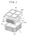
- FIG 1 is an exploded perspective view of the battery pack of the present embodiment.
- FIG 2 is a diagram showing a configuration of part of a case of the battery pack according to the present embodiment.
- FIG. 3 is a sectional view showing an internal configuration of the battery pack of the present embodiment.
- the battery pack (electricity storage device) 1 has a battery unit 2 and a case 3, in which the unit 2 is contained.
- the battery pack 1 is mounted on a vehicle.
- the battery pack 1 of the present embodiment can be mounted on a subject other than vehicles.
- the battery unit 2 has an electricity storage pack (electricity storage unit) 20, including a plurality of cells (electricity storage elements) 20a, and holding members (so-called end plates) 21 for holding the electricity storage unit 20 at both ends thereof.
- the cells 20a constituting the electricity storage pack 20 are electrically connected in series by connection members (bus bars) 22.
- the bus bars 22 are fixed to terminal portions 20b of the cells 20a with nuts.
- the bus bars 22 are not fixed to part (two in the present embodiment) of the plurality of cells 20a.
- the terminals of the cells 20a to which no bus bar is fixed are connected to an electrical component(s) (a motor, for example) outside the battery pack 1 through positive and negative wiring (not shown).
- the electricity storage pack 20 is used as a power source of the electrical component(s).
- a cylindrical secondary battery is used as the cell 20a.
- secondary batteries include the nickel-hydrogen battery and the lithium-ion battery.
- the shape of the cell 20a is not limited to the cylindrical shape, but may be other shapes, such as rectangular shapes.
- secondary batteries are used in the present embodiment, electric double-layer capacitors (condensers) may be used instead of the secondary batteries.
- the case 3 has a first case member 31 that provides the bottom and side faces of the case 3, and a second case member 32 that provides the upper face (top face) of the case 3.
- the top of the first case member 31 has an opening 31a, and the battery unit 2 is received through the opening 31a.
- the outer surface of the first case member 31 is provided with a plurality of radiator fins 31b for improving heat dissipation capacity of the first case member 31 (that is, the battery unit 2).
- the number of radiator fins 31b and the intervals between the radiator fins 31b may be appropriately set.
- the radiator fins 31b may be omitted.
- the first case member 31 is fixed to a vehicle body (not shown) with screws, for example.
- vehicle body herein means a floor panel or a frame of the vehicle, for example.
- the second case member 32 is put over the opening 31a of the first case member 31 and fixed to the first case member 31 with screws, for example. In this way, an enclosed space for housing the battery unit 2 is created.
- the second case member 32 is provided with a plurality of frame portions 32a in order to obtain enough strength.
- the first and second case members 31 and 32 may be made of a material that is excellent in heat conductivity, corrosion resistance, etc., such as a material that has a heat conductivity equal to or higher than the heat conductivity of a coolant 4 to be described later.
- the first and second case members 31 and 32 may be made of a metallic material, such as copper and iron.
- the space enclosed by the first and second case members 31 and 32 which is the space for housing the battery unit 2 and hereinafter also referred to as the housing chamber, is filled with the coolant 4 that is used to cool mainly the battery unit 2 (see FIG. 3 ).
- An electrically insulating oil and an inert liquid may be used as the coolant 4.
- a silicone oil may be used as the electrically insulating oil.
- As the inert liquid Fluorinert, Novec HFE (hydrofluoroether), and Novec 1230 (registered trademarks), made by 3M, which are fluorochemical inert liquids, can be used.
- a fan (not shown) as a stirring member may be provided in the housing chamber 3a of the case 3 (see FIG 3 ). In this case, it is possible to forcibly flow (circulate) the coolant 4 in the housing chamber 3a by driving (rotating) the fan. Thus, it is possible to improve the efficiency with which the battery unit 2 is cooled using the coolant 4.
- a recess 32b is formed in a substantially center portion of an inner wall surface (that is, the wall surface facing the battery unit 2) of the second case member 32.
- a gas sensor 5 for detecting the gas produced in the housing chamber 3a, that is, the gas produced by the cells 20a (see FIG. 3 ).
- a plurality of contact portions 32c1 to 32c3 that are protruded toward the battery unit 2 are formed on the inner wall surface of the second case member 32.
- the contact portions that have the same shape are designated by the same reference numerals.
- the top surfaces, facing the battery unit 2, of the contact portions 32c1 to 32c3 are flush with each other and are designed to be brought into contact with the surface of the coolant 4 as shown in FIG. 3 .
- the contact portions 32c1 to 32c3 may be integrally formed with the second case member 32.
- the contact portions 32c1 to 32c3 may be made of a material that is excellent in heat conductivity, corrosion resistance, etc. as in the case of the case member, such as a material that has a heat conductivity equal to or higher than the heat conductivity of the coolant 4 to be described later.
- a plurality of guide portions 32d each including an oblique surface that is oblique with respect to the vertical direction (that is, the gravitational direction) of the battery pack 1 are formed between the contact portions 32c1 to 32c3.
- the plurality of guide portions 32d radially extend toward the edges of the second case member 32 with the recess 32b centered.
- the guide portions 32b extend toward the opposed two of the edges of the second case member 32.
- These guide portions 32d are provided above the surface of the coolant 4 as shown in FIG. 3 .
- the entire guide portion 32d is positioned above the surface of the coolant 4, part of the guide portion 32d may be in contact with the coolant 4.
- the plurality of guide portions 32d join each other in an area near the recess 32b and in areas near the edges of the inner wall surface of the second case member 32.
- the plurality of guide portions 32d are formed by one common surface.
- the distance (vertical distance) between the oblique surface of each of the guide portions 32d and the battery unit 2 is the shortest near the edges of the second case member 32, and this distance is the longest around the recess 32b.
- the distance between the oblique surface of each of the guide portions 32d and the battery unit 2 increases from the peripheral portion of the second case member 32 to the center portion (recess 32b).
- the guide portion 32d may be formed by a surface from which the distance to the battery unit 2 varies stepwise.
- the output signal from the gas sensor 5 is supplied to a controller (not shown) disposed outside the battery pack 1.
- the controller detects whether gas is produced by the cells 20a based on the signal from the gas sensor 5.
- the controller can also be used as the controller for controlling the driving of the vehicle.
- the controller performs control to restrict charge and discharge of the electricity storage pack 20. In this way, it is possible to minimize the production of gas by the cells 20a.
- FIG. 4 is a sectional view of a battery pack of a modification of the first embodiment.
- the member that has the same function as that of the member shown in FIG. 3 is designated by the same reference numeral.
- an opening 32e is formed at a position of the recess 32b, and a discharging mechanism 6 for discharging the gas produced in the housing chamber 3a into the outside of the case 3 is provided at the opening 32e.
- the discharging mechanism 6 has a duct 61 connected to the opening 32e, and a valve (more specifically, relief valve) 62 provided in part of the duct 61.
- a valve more specifically, relief valve
- the gas sensor 5 is disposed at the position near the opening 32e where the gas sensor 5 does not obstruct flow of gas.
- the gas sensor 5 is provided in the configuration shown in FIG. 4 , the gas sensor 5 may be omitted. In this case, it is possible to detect the gas produced in the housing chamber 3a by using the valve 62. Specifically, when a mechanism that outputs an electric signal, for example, depending on whether the valve 62 is open or closed is provided, it is possible to detect the production of gas.
- the coolant 4 with which the case 3 is filled is in contact with the outer surface of the battery unit 2 and the inner wall surface of the first case member 31, so that it is possible to efficiently transfer the heat produced by the battery unit 2 to the first case member 31.
- the contact portions 32c1 to 32c3 formed on the inner wall surface of the second case member 32 are in contact with the coolant 4, so that it is possible to efficiently transfer the heat produced by the battery unit 2 also to the second case member 32.
- the guide portions 32d are formed on the inner wall surface of the second case member 32.
- the gas flows in the upward direction with respect to the battery pack 1 (toward the second case member 32, that is, the direction opposite to the gravitational direction) because the gas has a specific gravity less than the specific gravity of the coolant 4.
- the gas flows along the guide portions 32d.
- the guide portions 32d are oblique as described above, the gas flows along the guide portions 32d (oblique surface) and is led to the recess 32b as indicated by the arrow in FIG 2 .
- common areas that are part of the guide portions 32d and are located near the edges of the second case member 32 are positioned in the plane (imaginary plane) in which the plurality of terminal portions 20b of the electricity storage pack 20 are disposed, that is, above the plurality of terminal portions 20b.
- the gas produced at the terminal portions 20b is efficiently led from the common areas of the guide portions 32d to the recess 32b.
- the gas sensor 5 is disposed in the recess 32b, and it is therefore possible to efficiently (that is, accurately) detect the gas produced in the housing chamber 3a by using the gas sensor 5.
- the inner wall surface of the second case member 32 in a conic shape (see FIGS. 1 and 2 of JP-A-63-98953 ), for example, it is possible to efficiently lead the gas produced by the cells 20b to the predetermined position (the apex of the conic surface) similarly to the present embodiment.
- the conic inner wall surface is apart from the surface of the coolant 4. This means that an air space is formed between the conic inner wall surface and the surface of the coolant 4, which results in reduction in the efficiency of heat dissipation through the conic inner wall surface.
- the place to which the gas is to be led may be another portion than the center portion of the second case member 32.
- gas may be led to a place near the edges of the inner wall surface of the second case member 32.
- the recess 32b is provided at the position on the inner wall surface of the second case member 32 to which position the distances from the two terminal portions 20b of each cell 20 are equal to each other. Specifically, it suffices that the recess 32b is positioned so that, when gas is produced by the two terminal portions 20b of a cell 20a, the gas travels along respective paths of which the lengths are substantially equal to each other, to reach the recess 32b.
- a fan for stirring the coolant 4 is disposed between one holding member 21 and the side wall of the first case member 31 in the configuration shown in FIG 3 , for example, the position at which the recess 32b is provided is shifted from the center portion of the inner wall surface of the second case member 32.
- the electricity storage device is designed so that gas is led to a substantially center portion of the second case member 32 in accordance with the present embodiment, it is possible to substantially uniformly apply, to the entire inner wall surface of the case 3, the pressure in the housing chamber 3a that builds up when gas is produced.
- pressure in the housing chamber 3a that builds up when gas is produced.
- pressure difference can occur in the housing chamber 3a. This is because, when gas is produced at each of the two terminal portions 20b of a cell 20a, for example, the distances that the gas travels from the respective terminal portions 20b to the recess 32b differ from each other.
- the configuration is adopted in which gas is led to a position offset from the center portion of the second case member 32, there is a possibility that part of the gas is not efficiently led to the recess 32b, and pressure difference can occur in the housing chamber 3a.
- the plurality of contact portions 32c1 to 32c3 and the plurality of guide portions 32d are provided on the inner wall surface of the second case member 32, and the number of the contact portions 32c1 to 32c3 and the number of the plurality of guide portions 32d may be appropriately set.
- the contact portions 32c2 and 32c3 may be omitted, and a guide portion 32d that is formed of a single oblique surface may be formed.
- the contact portions 32c1 to 32c3 in the vertical direction (gravitational direction) of the battery pack 1 are substantially equal to each other.
- these dimensions of the contact portions 32c1 to 32c3 may differ from each other. In this case, when a contact portion protrudes more than another contact portion, the former contact portion is dipped into the coolant 4 more than the latter contact portion.
- the shape of the contact portions 32c1 to 32c3 is not limited to the shape shown in FIG. 2 .
- the shape is arbitrary as long as the contact portion is brought into contact with the coolant 4.
- each of the guide portions 32d has an oblique surface, which lead gas to the recess 32b.
- the guide portions may be a plurality of grooves that are formed between the contact portions.
- the sectional shape of the groove may be V-shape or a semicircular shape, for example.
- a pressure sensor for sensing the pressure in the housing chamber 3a may be provided in the housing chamber 3a. Specific description will be given below.
- the pressure sensor may be attached to the battery unit 2, more specifically, a bus bar 22, for example.
- a bus bar 22 it is possible to attach the pressure sensor to the battery unit 2 (bus bar 22) in advance before the battery unit 2 is housed in the case 3 (first case member 31), which makes it easy to assemble the battery pack 1.
- the pressure sensor when the purpose is to detect the change in pressure in the housing chamber 3a, the pressure sensor may be attached to the inner wall surface of the case 3.
- the pressure sensor when the pressure sensor is provided on the battery unit 2 as described above, it is possible to assemble the battery pack 1 with the wiring for the pressure sensor and the wiring for the battery unit 2 bundled together.
- the pressure sensor is provided on a bus bar 22, it is possible to easily attach the pressure sensor to the bus bar 22, and it is also possible to bundle the wiring for the pressure sensor and the wiring for the battery unit 2.
Landscapes
- Chemical & Material Sciences (AREA)
- Chemical Kinetics & Catalysis (AREA)
- Electrochemistry (AREA)
- General Chemical & Material Sciences (AREA)
- Engineering & Computer Science (AREA)
- Manufacturing & Machinery (AREA)
- Secondary Cells (AREA)
- Battery Mounting, Suspending (AREA)
- Electric Double-Layer Capacitors Or The Like (AREA)
- Gas-Filled Discharge Tubes (AREA)
- Spinning Or Twisting Of Yarns (AREA)
Claims (11)
- Elektrische Speichervorrichtung (1), gekennzeichnet durch:eine elektrische Speichereinheit (2); undein Gehäuse (3), das die elektrische Speichereinheit und ein Kühlmittel (4) zum Kühlen der elektrischen Speichereinheit enthält, wobei das Gehäuse Folgendes aufweist:einen Führungsabschnitt (32d) an einer inneren Wandfläche oberhalb der elektrischen Speichereinheit, wobei der Führungsabschnitt einen schrägen Abschnitt zum Leiten des Gases an eine vorbestimmte Position aufweist, wenn das Gas durch die elektrische Speichereinheit erzeugt ist; undeinen Kontaktabschnitt (32c1 - 31c3), der in eine Richtung der elektrischen Speichereinheit hinsichtlich des schrägen Abschnitts des Führungsabschnitts vorragt und mit dem Kühlmittel in Kontakt gebracht ist.
- Elektrische Speichervorrichtung nach Anspruch 1, wobei
eine Vielzahl der Führungsabschnitte vorgesehen sind, und
sich die Vielzahl der Führungsabschnitte von einem Umfangsabschnitt der inneren Wandfläche zu der vorbestimmten Position erstreckt. - Elektrische Speichervorrichtung nach Anspruch 2, wobei
der schräge Abschnitt derart ausgebildet ist, dass ein Abstand von dem schrägen Abschnitt zu der elektrischen Speichereinheit in einer Schwerkraftrichtung von dem Umfangsabschnitt zu der vorbestimmten Position hin ansteigt. - Elektrische Speichervorrichtung nach einem der Ansprüche 1 bis 3, ferner mit
einem Gassensor (5) zum Erfassen des Gases,
wobei der Gassensor an der vorbestimmten Position an dem Gehäuse vorgesehen ist. - Elektrische Speichervorrichtung nach einem der Ansprüche 1 bis 4, ferner mit
einem Abgabemechanismus (6), der mit dem Gehäuse an der vorbestimmten Position verbunden ist, um das Gas zu der Außenseite der elektrischen Speichervorrichtung hin zu leiten. - Elektrische Speichervorrichtung nach einem der Ansprüche 1 bis 5, wobei:die elektrische Speichereinheit eine Vielzahl von elektrischen Speicherelementen aufweist, wobei jedes der elektrischen Speicherelemente eine Vielzahl von Anschlüssen hat, undAbstände von der Vielzahl der Anschlüsse von jedem der elektrischen Speicherelemente zu der vorbestimmten Position im Wesentlichen gleich zueinander sind.
- Elektrische Speichervorrichtung nach einem der Ansprüche 1 bis 5, ferner mit:einem Drucksensor zum Fühlen eines Drucks in dem Gehäuse, wobei die elektrische Speichereinheit eine Vielzahl von elektrischen Speicherelementen aufweist, undder Drucksensor an einem Verbindungsbauteil (22) befestigt ist zur Verwendung bei einem elektrischen Verbinden der Vielzahl der elektrischen Speicherelemente.
- Elektrische Speichervorrichtung nach Anspruch 6, ferner mit
einem Drucksensor zum Fühlen eines Drucks in dem Gehäuse,
wobei der Drucksensor an einem Verbindungsbauteil befestigt ist, zur Verwendung bei einem elektrischen Verbinden der Vielzahl der elektrischen Speicherelemente. - Elektrische Speichervorrichtung nach einem der Ansprüche 1 bis 8, wobei
das Gehäuse Folgendes aufweist: ein erstes Gehäusebauteil (31), das eine Öffnung aufweist, durch die das Gehäuse die elektrische Speichereinheit und das Kühlmittel aufnimmt; und ein zweites Gehäusebauteil (32), das an dem ersten Gehäusebauteil befestigt ist, um die Öffnung abzudecken, und den Kontaktabschnitt und den Führungsabschnitt aufweist. - Elektrische Speichervorrichtung nach einem der Ansprüche 1 bis 9, wobei:eine Vielzahl der Kontaktabschnitte an der inneren Wandfläche ausgebildet sind;der Führungsabschnitt zwischen jedem Paar von benachbarten Kontaktabschnitten ausgebildet ist; undder schräge Abschnitt eine schräge Fläche ist, die zwischen jedem Paar von benachbarten Kontaktabschnitten positioniert ist.
- Elektrische Speichervorrichtung nach einem der Ansprüche 6 bis 8, wobei der Kontaktabschnitt nicht an einem Teil der inneren Wandfläche ausgebildet ist, die über der Vielzahl von Anschlüssen positioniert ist.
Applications Claiming Priority (2)
| Application Number | Priority Date | Filing Date | Title |
|---|---|---|---|
| JP2007090153A JP4438813B2 (ja) | 2007-03-30 | 2007-03-30 | 蓄電装置 |
| PCT/IB2008/000564 WO2008120054A2 (en) | 2007-03-30 | 2008-03-11 | Electricity storage device |
Publications (2)
| Publication Number | Publication Date |
|---|---|
| EP2132805A2 EP2132805A2 (de) | 2009-12-16 |
| EP2132805B1 true EP2132805B1 (de) | 2010-09-22 |
Family
ID=39739895
Family Applications (1)
| Application Number | Title | Priority Date | Filing Date |
|---|---|---|---|
| EP20080719272 Not-in-force EP2132805B1 (de) | 2007-03-30 | 2008-03-11 | Stromspeichervorrichtung |
Country Status (7)
| Country | Link |
|---|---|
| US (1) | US8852792B2 (de) |
| EP (1) | EP2132805B1 (de) |
| JP (1) | JP4438813B2 (de) |
| CN (1) | CN101578721B (de) |
| AT (1) | ATE482480T1 (de) |
| DE (1) | DE602008002729D1 (de) |
| WO (1) | WO2008120054A2 (de) |
Families Citing this family (12)
| Publication number | Priority date | Publication date | Assignee | Title |
|---|---|---|---|---|
| DE102008043789A1 (de) * | 2008-11-17 | 2010-05-20 | Robert Bosch Gmbh | Batteriemodul |
| JP6064633B2 (ja) * | 2013-02-05 | 2017-01-25 | 株式会社豊田自動織機 | 電池パック |
| TWM472953U (zh) * | 2013-05-22 | 2014-02-21 | Csb Battery Co Ltd | 濕式電池組 |
| US9509020B1 (en) * | 2014-03-27 | 2016-11-29 | Amazon Technologies, Inc. | Volumetric battery health sensor |
| JP6662319B2 (ja) | 2017-02-03 | 2020-03-11 | オムロン株式会社 | 異常検出装置 |
| US10293747B2 (en) * | 2017-09-22 | 2019-05-21 | Ford Global Technologies, Llc | Systems and methods for vehicle battery leak detection and mitigation |
| DE102017129166B4 (de) * | 2017-12-07 | 2023-06-29 | Vorwerk & Co. Interholding Gesellschaft mit beschränkter Haftung | Reinigungsgerät mit einem Akkumulator |
| US10756396B2 (en) | 2018-03-23 | 2020-08-25 | Chongqing Jinkang New Energy Vehicle Co., Ltd. | Battery cells for battery packs in electric vehicles |
| DE102020205930A1 (de) | 2020-05-12 | 2021-11-18 | Mahle International Gmbh | Akkumulator |
| KR102857146B1 (ko) * | 2021-07-29 | 2025-09-10 | 컨템포러리 엠퍼렉스 테크놀로지 (홍콩) 리미티드 | 배터리 셀 및 그 제조방법과 제조 시스템, 배터리 및 전기장치 |
| HUE071288T2 (hu) | 2021-07-29 | 2025-08-28 | Contemporary Amperex Technology Hong Kong Ltd | Akkumulátorcella, gyártási eljárás és ehhez való gyártási rendszer, akkumulátor és elektromos berendezés |
| WO2025181575A1 (en) * | 2024-02-26 | 2025-09-04 | H55 Sa | A battery module |
Family Cites Families (13)
| Publication number | Priority date | Publication date | Assignee | Title |
|---|---|---|---|---|
| US2212368A (en) * | 1936-05-28 | 1940-08-20 | Electric Storage Battery Co | Electric storage battery |
| DE3375707D1 (en) * | 1982-10-28 | 1988-03-24 | Gen Motors Corp | Low silhouette venting system for electric storage battery |
| JPS6142283U (ja) | 1984-08-20 | 1986-03-18 | 株式会社安川電機 | 手動指令器 |
| JPS6361758U (de) | 1986-10-13 | 1988-04-23 | ||
| JPS6398953A (ja) | 1986-10-14 | 1988-04-30 | Yuasa Battery Co Ltd | 油漬電池装置の排油及び注油方法 |
| DE9005603U1 (de) | 1990-05-17 | 1990-07-19 | Accumulatorenwerke Hoppecke Carl Zoellner & Sohn GmbH & Co KG, 5790 Brilon | Bleiakkumulator |
| ATE122177T1 (de) | 1991-07-19 | 1995-05-15 | Hoppecke Zoellner Sohn Accu | Akkumulator, insbesondere bleiakkumulator, vorzugsweise für nutzkraftwagen. |
| JP2967904B2 (ja) * | 1994-03-01 | 1999-10-25 | 本田技研工業株式会社 | 電動車両用バッテリのガス排出装置 |
| JPH0822815A (ja) * | 1994-07-07 | 1996-01-23 | Yuasa Corp | 蓄電池の排気構造 |
| JP2000133225A (ja) * | 1998-10-30 | 2000-05-12 | Sanyo Electric Co Ltd | 組電池 |
| JP3638102B2 (ja) | 1999-09-30 | 2005-04-13 | Necトーキン栃木株式会社 | 電池パック |
| JP2006127921A (ja) * | 2004-10-29 | 2006-05-18 | Sanyo Electric Co Ltd | 電源装置 |
| JP2007224877A (ja) * | 2006-02-27 | 2007-09-06 | Denso Corp | 内燃機関の排気管への排気センサ取付け構造 |
-
2007
- 2007-03-30 JP JP2007090153A patent/JP4438813B2/ja active Active
-
2008
- 2008-03-11 DE DE200860002729 patent/DE602008002729D1/de active Active
- 2008-03-11 AT AT08719272T patent/ATE482480T1/de not_active IP Right Cessation
- 2008-03-11 WO PCT/IB2008/000564 patent/WO2008120054A2/en not_active Ceased
- 2008-03-11 EP EP20080719272 patent/EP2132805B1/de not_active Not-in-force
- 2008-03-11 CN CN2008800015175A patent/CN101578721B/zh not_active Expired - Fee Related
- 2008-03-11 US US12/517,244 patent/US8852792B2/en active Active
Also Published As
| Publication number | Publication date |
|---|---|
| CN101578721B (zh) | 2011-08-31 |
| US8852792B2 (en) | 2014-10-07 |
| WO2008120054A3 (en) | 2008-11-27 |
| WO2008120054A2 (en) | 2008-10-09 |
| CN101578721A (zh) | 2009-11-11 |
| ATE482480T1 (de) | 2010-10-15 |
| DE602008002729D1 (de) | 2010-11-04 |
| US20100062322A1 (en) | 2010-03-11 |
| EP2132805A2 (de) | 2009-12-16 |
| JP2008251307A (ja) | 2008-10-16 |
| JP4438813B2 (ja) | 2010-03-24 |
Similar Documents
| Publication | Publication Date | Title |
|---|---|---|
| EP2132805B1 (de) | Stromspeichervorrichtung | |
| JP7625653B2 (ja) | 上部冷却方式バッテリーパック | |
| CN108695458B (zh) | 电池组和包括电池组的电动车辆 | |
| CN100405634C (zh) | 二次电池及具有二次电池的二次电池模块 | |
| CN101395737B (zh) | 中型或大型电池模块 | |
| KR101501026B1 (ko) | 우수한 냉각 효율성과 콤팩트한 구조의 전지모듈 | |
| CN100423322C (zh) | 电池组 | |
| CN101647149B (zh) | 蓄电装置 | |
| EP3567670A1 (de) | Batteriemodul | |
| EP2178135A1 (de) | Wiederaufladbare Batterie, Anordnung mit solch einer Batterie und Batteriemodul | |
| KR101708367B1 (ko) | 배터리 팩 | |
| US11621447B2 (en) | Secondary battery pack including cell frame with coating prevention part | |
| US20230344027A1 (en) | Battery module having sensing module assembly | |
| CN113939948A (zh) | 包括单元框架的电池模块 | |
| KR102026386B1 (ko) | 배터리 모듈 | |
| KR102315974B1 (ko) | 전장 어셈블리 및 상기 전장 어셈블리를 포함하는 배터리 팩 | |
| CN208127265U (zh) | 电池包 | |
| US20240297392A1 (en) | Cell Module Assembly and Battery Pack Comprising the Same | |
| US9356326B2 (en) | Top cover and battery pack having the same | |
| KR20170027545A (ko) | 이차 전지용 카트리지 | |
| KR101134134B1 (ko) | 이차전지 모듈 | |
| JP2010015951A (ja) | 蓄電装置 | |
| EP3772122B1 (de) | Batteriemodul mit einer multifunktionalen endplatte | |
| KR20190074402A (ko) | 이차전지 모듈 | |
| KR101586641B1 (ko) | 전지팩 모듈 하우징 |
Legal Events
| Date | Code | Title | Description |
|---|---|---|---|
| PUAI | Public reference made under article 153(3) epc to a published international application that has entered the european phase |
Free format text: ORIGINAL CODE: 0009012 |
|
| 17P | Request for examination filed |
Effective date: 20090618 |
|
| AK | Designated contracting states |
Kind code of ref document: A2 Designated state(s): AT BE BG CH CY CZ DE DK EE ES FI FR GB GR HR HU IE IS IT LI LT LU LV MC MT NL NO PL PT RO SE SI SK TR |
|
| GRAP | Despatch of communication of intention to grant a patent |
Free format text: ORIGINAL CODE: EPIDOSNIGR1 |
|
| DAX | Request for extension of the european patent (deleted) | ||
| GRAC | Information related to communication of intention to grant a patent modified |
Free format text: ORIGINAL CODE: EPIDOSCIGR1 |
|
| GRAS | Grant fee paid |
Free format text: ORIGINAL CODE: EPIDOSNIGR3 |
|
| GRAA | (expected) grant |
Free format text: ORIGINAL CODE: 0009210 |
|
| AK | Designated contracting states |
Kind code of ref document: B1 Designated state(s): AT BE BG CH CY CZ DE DK EE ES FI FR GB GR HR HU IE IS IT LI LT LU LV MC MT NL NO PL PT RO SE SI SK TR |
|
| REG | Reference to a national code |
Ref country code: GB Ref legal event code: FG4D |
|
| REG | Reference to a national code |
Ref country code: CH Ref legal event code: EP |
|
| REG | Reference to a national code |
Ref country code: IE Ref legal event code: FG4D |
|
| REF | Corresponds to: |
Ref document number: 602008002729 Country of ref document: DE Date of ref document: 20101104 Kind code of ref document: P |
|
| PG25 | Lapsed in a contracting state [announced via postgrant information from national office to epo] |
Ref country code: AT Free format text: LAPSE BECAUSE OF FAILURE TO SUBMIT A TRANSLATION OF THE DESCRIPTION OR TO PAY THE FEE WITHIN THE PRESCRIBED TIME-LIMIT Effective date: 20100922 Ref country code: FI Free format text: LAPSE BECAUSE OF FAILURE TO SUBMIT A TRANSLATION OF THE DESCRIPTION OR TO PAY THE FEE WITHIN THE PRESCRIBED TIME-LIMIT Effective date: 20100922 Ref country code: NO Free format text: LAPSE BECAUSE OF FAILURE TO SUBMIT A TRANSLATION OF THE DESCRIPTION OR TO PAY THE FEE WITHIN THE PRESCRIBED TIME-LIMIT Effective date: 20101222 Ref country code: LT Free format text: LAPSE BECAUSE OF FAILURE TO SUBMIT A TRANSLATION OF THE DESCRIPTION OR TO PAY THE FEE WITHIN THE PRESCRIBED TIME-LIMIT Effective date: 20100922 |
|
| REG | Reference to a national code |
Ref country code: NL Ref legal event code: VDEP Effective date: 20100922 |
|
| LTIE | Lt: invalidation of european patent or patent extension |
Effective date: 20100922 |
|
| PG25 | Lapsed in a contracting state [announced via postgrant information from national office to epo] |
Ref country code: SI Free format text: LAPSE BECAUSE OF FAILURE TO SUBMIT A TRANSLATION OF THE DESCRIPTION OR TO PAY THE FEE WITHIN THE PRESCRIBED TIME-LIMIT Effective date: 20100922 Ref country code: PL Free format text: LAPSE BECAUSE OF FAILURE TO SUBMIT A TRANSLATION OF THE DESCRIPTION OR TO PAY THE FEE WITHIN THE PRESCRIBED TIME-LIMIT Effective date: 20100922 Ref country code: HR Free format text: LAPSE BECAUSE OF FAILURE TO SUBMIT A TRANSLATION OF THE DESCRIPTION OR TO PAY THE FEE WITHIN THE PRESCRIBED TIME-LIMIT Effective date: 20100922 |
|
| PG25 | Lapsed in a contracting state [announced via postgrant information from national office to epo] |
Ref country code: SE Free format text: LAPSE BECAUSE OF FAILURE TO SUBMIT A TRANSLATION OF THE DESCRIPTION OR TO PAY THE FEE WITHIN THE PRESCRIBED TIME-LIMIT Effective date: 20100922 Ref country code: GR Free format text: LAPSE BECAUSE OF FAILURE TO SUBMIT A TRANSLATION OF THE DESCRIPTION OR TO PAY THE FEE WITHIN THE PRESCRIBED TIME-LIMIT Effective date: 20101223 Ref country code: LV Free format text: LAPSE BECAUSE OF FAILURE TO SUBMIT A TRANSLATION OF THE DESCRIPTION OR TO PAY THE FEE WITHIN THE PRESCRIBED TIME-LIMIT Effective date: 20100922 |
|
| PG25 | Lapsed in a contracting state [announced via postgrant information from national office to epo] |
Ref country code: IT Free format text: LAPSE BECAUSE OF FAILURE TO SUBMIT A TRANSLATION OF THE DESCRIPTION OR TO PAY THE FEE WITHIN THE PRESCRIBED TIME-LIMIT Effective date: 20100922 Ref country code: PT Free format text: LAPSE BECAUSE OF FAILURE TO SUBMIT A TRANSLATION OF THE DESCRIPTION OR TO PAY THE FEE WITHIN THE PRESCRIBED TIME-LIMIT Effective date: 20110124 Ref country code: EE Free format text: LAPSE BECAUSE OF FAILURE TO SUBMIT A TRANSLATION OF THE DESCRIPTION OR TO PAY THE FEE WITHIN THE PRESCRIBED TIME-LIMIT Effective date: 20100922 Ref country code: SK Free format text: LAPSE BECAUSE OF FAILURE TO SUBMIT A TRANSLATION OF THE DESCRIPTION OR TO PAY THE FEE WITHIN THE PRESCRIBED TIME-LIMIT Effective date: 20100922 Ref country code: CZ Free format text: LAPSE BECAUSE OF FAILURE TO SUBMIT A TRANSLATION OF THE DESCRIPTION OR TO PAY THE FEE WITHIN THE PRESCRIBED TIME-LIMIT Effective date: 20100922 Ref country code: RO Free format text: LAPSE BECAUSE OF FAILURE TO SUBMIT A TRANSLATION OF THE DESCRIPTION OR TO PAY THE FEE WITHIN THE PRESCRIBED TIME-LIMIT Effective date: 20100922 Ref country code: IS Free format text: LAPSE BECAUSE OF FAILURE TO SUBMIT A TRANSLATION OF THE DESCRIPTION OR TO PAY THE FEE WITHIN THE PRESCRIBED TIME-LIMIT Effective date: 20110122 Ref country code: NL Free format text: LAPSE BECAUSE OF FAILURE TO SUBMIT A TRANSLATION OF THE DESCRIPTION OR TO PAY THE FEE WITHIN THE PRESCRIBED TIME-LIMIT Effective date: 20100922 |
|
| PG25 | Lapsed in a contracting state [announced via postgrant information from national office to epo] |
Ref country code: BE Free format text: LAPSE BECAUSE OF FAILURE TO SUBMIT A TRANSLATION OF THE DESCRIPTION OR TO PAY THE FEE WITHIN THE PRESCRIBED TIME-LIMIT Effective date: 20100922 |
|
| PG25 | Lapsed in a contracting state [announced via postgrant information from national office to epo] |
Ref country code: ES Free format text: LAPSE BECAUSE OF FAILURE TO SUBMIT A TRANSLATION OF THE DESCRIPTION OR TO PAY THE FEE WITHIN THE PRESCRIBED TIME-LIMIT Effective date: 20110102 |
|
| PLBE | No opposition filed within time limit |
Free format text: ORIGINAL CODE: 0009261 |
|
| STAA | Information on the status of an ep patent application or granted ep patent |
Free format text: STATUS: NO OPPOSITION FILED WITHIN TIME LIMIT |
|
| 26N | No opposition filed |
Effective date: 20110623 |
|
| PG25 | Lapsed in a contracting state [announced via postgrant information from national office to epo] |
Ref country code: DK Free format text: LAPSE BECAUSE OF FAILURE TO SUBMIT A TRANSLATION OF THE DESCRIPTION OR TO PAY THE FEE WITHIN THE PRESCRIBED TIME-LIMIT Effective date: 20100922 |
|
| REG | Reference to a national code |
Ref country code: DE Ref legal event code: R097 Ref document number: 602008002729 Country of ref document: DE Effective date: 20110623 |
|
| PG25 | Lapsed in a contracting state [announced via postgrant information from national office to epo] |
Ref country code: MC Free format text: LAPSE BECAUSE OF NON-PAYMENT OF DUE FEES Effective date: 20110331 |
|
| PG25 | Lapsed in a contracting state [announced via postgrant information from national office to epo] |
Ref country code: MT Free format text: LAPSE BECAUSE OF FAILURE TO SUBMIT A TRANSLATION OF THE DESCRIPTION OR TO PAY THE FEE WITHIN THE PRESCRIBED TIME-LIMIT Effective date: 20100922 |
|
| REG | Reference to a national code |
Ref country code: IE Ref legal event code: MM4A |
|
| PG25 | Lapsed in a contracting state [announced via postgrant information from national office to epo] |
Ref country code: IE Free format text: LAPSE BECAUSE OF NON-PAYMENT OF DUE FEES Effective date: 20110311 |
|
| REG | Reference to a national code |
Ref country code: CH Ref legal event code: PL |
|
| REG | Reference to a national code |
Ref country code: GB Ref legal event code: 746 Effective date: 20121219 |
|
| PG25 | Lapsed in a contracting state [announced via postgrant information from national office to epo] |
Ref country code: CH Free format text: LAPSE BECAUSE OF NON-PAYMENT OF DUE FEES Effective date: 20120331 Ref country code: LI Free format text: LAPSE BECAUSE OF NON-PAYMENT OF DUE FEES Effective date: 20120331 |
|
| REG | Reference to a national code |
Ref country code: DE Ref legal event code: R084 Ref document number: 602008002729 Country of ref document: DE Effective date: 20121213 |
|
| PG25 | Lapsed in a contracting state [announced via postgrant information from national office to epo] |
Ref country code: LU Free format text: LAPSE BECAUSE OF NON-PAYMENT OF DUE FEES Effective date: 20110311 Ref country code: CY Free format text: LAPSE BECAUSE OF FAILURE TO SUBMIT A TRANSLATION OF THE DESCRIPTION OR TO PAY THE FEE WITHIN THE PRESCRIBED TIME-LIMIT Effective date: 20100922 |
|
| PG25 | Lapsed in a contracting state [announced via postgrant information from national office to epo] |
Ref country code: BG Free format text: LAPSE BECAUSE OF FAILURE TO SUBMIT A TRANSLATION OF THE DESCRIPTION OR TO PAY THE FEE WITHIN THE PRESCRIBED TIME-LIMIT Effective date: 20101222 Ref country code: TR Free format text: LAPSE BECAUSE OF FAILURE TO SUBMIT A TRANSLATION OF THE DESCRIPTION OR TO PAY THE FEE WITHIN THE PRESCRIBED TIME-LIMIT Effective date: 20100922 |
|
| PG25 | Lapsed in a contracting state [announced via postgrant information from national office to epo] |
Ref country code: HU Free format text: LAPSE BECAUSE OF FAILURE TO SUBMIT A TRANSLATION OF THE DESCRIPTION OR TO PAY THE FEE WITHIN THE PRESCRIBED TIME-LIMIT Effective date: 20100922 |
|
| REG | Reference to a national code |
Ref country code: FR Ref legal event code: PLFP Year of fee payment: 8 |
|
| PGFP | Annual fee paid to national office [announced via postgrant information from national office to epo] |
Ref country code: DE Payment date: 20150305 Year of fee payment: 8 |
|
| PGFP | Annual fee paid to national office [announced via postgrant information from national office to epo] |
Ref country code: FR Payment date: 20150309 Year of fee payment: 8 Ref country code: GB Payment date: 20150311 Year of fee payment: 8 |
|
| REG | Reference to a national code |
Ref country code: DE Ref legal event code: R119 Ref document number: 602008002729 Country of ref document: DE |
|
| GBPC | Gb: european patent ceased through non-payment of renewal fee |
Effective date: 20160311 |
|
| REG | Reference to a national code |
Ref country code: FR Ref legal event code: ST Effective date: 20161130 |
|
| PG25 | Lapsed in a contracting state [announced via postgrant information from national office to epo] |
Ref country code: GB Free format text: LAPSE BECAUSE OF NON-PAYMENT OF DUE FEES Effective date: 20160311 Ref country code: DE Free format text: LAPSE BECAUSE OF NON-PAYMENT OF DUE FEES Effective date: 20161001 Ref country code: FR Free format text: LAPSE BECAUSE OF NON-PAYMENT OF DUE FEES Effective date: 20160331 |