EP2132808B1 - Batterie - Google Patents
Batterie Download PDFInfo
- Publication number
- EP2132808B1 EP2132808B1 EP08734346.3A EP08734346A EP2132808B1 EP 2132808 B1 EP2132808 B1 EP 2132808B1 EP 08734346 A EP08734346 A EP 08734346A EP 2132808 B1 EP2132808 B1 EP 2132808B1
- Authority
- EP
- European Patent Office
- Prior art keywords
- connector
- battery
- contact element
- section
- welding lug
- Prior art date
- Legal status (The legal status is an assumption and is not a legal conclusion. Google has not performed a legal analysis and makes no representation as to the accuracy of the status listed.)
- Active
Links
Images


Classifications
-
- H—ELECTRICITY
- H01—ELECTRIC ELEMENTS
- H01M—PROCESSES OR MEANS, e.g. BATTERIES, FOR THE DIRECT CONVERSION OF CHEMICAL ENERGY INTO ELECTRICAL ENERGY
- H01M50/00—Constructional details or processes of manufacture of the non-active parts of electrochemical cells other than fuel cells, e.g. hybrid cells
- H01M50/50—Current conducting connections for cells or batteries
- H01M50/528—Fixed electrical connections, i.e. not intended for disconnection
- H01M50/529—Intercell connections through partitions, e.g. in a battery casing
-
- H—ELECTRICITY
- H01—ELECTRIC ELEMENTS
- H01M—PROCESSES OR MEANS, e.g. BATTERIES, FOR THE DIRECT CONVERSION OF CHEMICAL ENERGY INTO ELECTRICAL ENERGY
- H01M50/00—Constructional details or processes of manufacture of the non-active parts of electrochemical cells other than fuel cells, e.g. hybrid cells
- H01M50/50—Current conducting connections for cells or batteries
- H01M50/531—Electrode connections inside a battery casing
- H01M50/536—Electrode connections inside a battery casing characterised by the method of fixing the leads to the electrodes, e.g. by welding
-
- H—ELECTRICITY
- H01—ELECTRIC ELEMENTS
- H01M—PROCESSES OR MEANS, e.g. BATTERIES, FOR THE DIRECT CONVERSION OF CHEMICAL ENERGY INTO ELECTRICAL ENERGY
- H01M50/00—Constructional details or processes of manufacture of the non-active parts of electrochemical cells other than fuel cells, e.g. hybrid cells
- H01M50/50—Current conducting connections for cells or batteries
- H01M50/531—Electrode connections inside a battery casing
- H01M50/54—Connection of several leads or tabs of plate-like electrode stacks, e.g. electrode pole straps or bridges
- H01M50/541—Connection of several leads or tabs of plate-like electrode stacks, e.g. electrode pole straps or bridges for lead-acid accumulators
-
- Y—GENERAL TAGGING OF NEW TECHNOLOGICAL DEVELOPMENTS; GENERAL TAGGING OF CROSS-SECTIONAL TECHNOLOGIES SPANNING OVER SEVERAL SECTIONS OF THE IPC; TECHNICAL SUBJECTS COVERED BY FORMER USPC CROSS-REFERENCE ART COLLECTIONS [XRACs] AND DIGESTS
- Y02—TECHNOLOGIES OR APPLICATIONS FOR MITIGATION OR ADAPTATION AGAINST CLIMATE CHANGE
- Y02E—REDUCTION OF GREENHOUSE GAS [GHG] EMISSIONS, RELATED TO ENERGY GENERATION, TRANSMISSION OR DISTRIBUTION
- Y02E60/00—Enabling technologies; Technologies with a potential or indirect contribution to GHG emissions mitigation
- Y02E60/10—Energy storage using batteries
Definitions
- the invention relates to a battery having at least one battery cell connector comprising (a) a connector having a cuboidal shape for connecting to at least one plate, in particular a pole plate set, to a bottom of the connector and (b) a welding tab electrically conductive to a connector (c) wherein, in the installed position of the battery, the connector is substantially horizontal and the welding tab is substantially vertical, and (d) the connector is a top side opposite the bottom and (e) at least one adjacent to the bottom Long side has, where the welding tab is connected to the connector.
- Such a battery is for example from the DE 103 23 529 B3 or from the DE 24 47 639 known.
- Such batteries in the form of lead-acid batteries are used, for example, as a starter battery in an automobile.
- a battery consists of a plurality of galvanic cells, which are connected in series and separated from each other by an electrically insulating partition.
- Each of the galvanic cells comprises a positive and a negative plate set, each of which is composed of several pole plates.
- a battery cell connector electrically and mechanically interconnects the pole plates of a plate set and, in addition, electrically contacts the plate set of one galvanic cell via another battery cell connection element to another plate set of another galvanic cell through the dividing wall.
- a connecting element for connecting cells to accumulators is from the EP 1 691 431 A1 known.
- the battery connecting elements are aligned relative to each other and relative to a recess in the partition wall. Subsequently, the welding flaps of two battery cell connecting elements arranged on both sides of the dividing wall are welded together and thus electrically connected to one another.
- the connector In lead-acid batteries, the connector is usually made entirely of lead, which has a relatively low electrical conductivity for a metal.
- Lead-acid batteries generally only have voltages between 6 volts and 48 volts. In modern motor vehicles such as commercial vehicles, however, high power levels of up to several kilowatts are required, so that large currents flow through the battery cell connection elements under load. With such currents, undesirable heating occurs due to the internal resistance of the battery, which is disadvantageous. The internal resistance of the battery also adversely limits the maximum power that can be delivered by the battery.
- the invention has for its object to provide a battery with reduced internal resistance.
- the invention solves the problem by a generic battery in which the welding strap is electrically connected to the connector via at least one contact element arranged laterally on the welding strap and leading onto the surface of the connector.
- a battery having such a battery cell connection element that an electric current which flows from the pole plates via the battery cell connection element experiences a lower electrical resistance than if the battery cell connection element were produced with the same amount of material without the contact element.
- the contact element makes this available for the electrical conduction of the current Standing material of the battery cell connection element optimally used for the flow of current, so that a reduced internal resistance of the battery can be achieved. This reduces the unwanted heating of the battery during operation and allows a higher power output of the battery.
- the invention alternatively allows the saving of material for the production of the battery cell connection element, for example of lead.
- a cuboidal basic shape means that it is possible, but not necessary, for the connector to be rectangular in the strict mathematical sense. Rather, it is possible for the connector to deviate from the cuboidal shape, for example by having more than six surfaces, two opposite sides not parallel to each other, or contiguous surfaces at a different angle than a right angle. Such modifications are known in the art.
- the connector extends substantially horizontally, it is to be understood that it is possible, but not necessary, for the connector to be strictly horizontal. It is particularly sufficient if the connector extends at an angle of less than 10 ° to the horizontal. The same applies to the feature that the welding flap extends substantially vertically. Again, deviations of, for example, less than 10 ° from the vertical are considered substantially vertical.
- the battery is a lead-acid battery, in particular a commercial vehicle lead-acid battery.
- Utility vehicle lead-acid batteries differ, for example, from passenger car or motorcycle lead-acid batteries in that the welding strap is arranged centrally on the longitudinal side of the connector.
- the weld tab has two contact elements located laterally on both sides of the weld tab, leading to the surface of the connector, and electrically connecting the weld tab to the connector.
- the contact elements are constructed, for example, mirror-symmetrical to each other, so that the battery cell connecting element is also constructed mirror-symmetrically to a mirror plane.
- the contact element has a cross-section which increases with decreasing distance from the top side of the connector. It is also advantageous that the battery cell connection element can be removed so easily from a mold.
- the contact element Since an electric current originating from a pole plate, which is connected to the connector at an outer end of the connector, has to overcome a particularly high electrical resistance, it is provided in a preferred embodiment that the contact element has a cross-section which increases with increasing Distance from the welding tab increases. In this way, the electrical resistance is reduced, the current must overcome by a laterally pole plate.
- the contact member has a connector side transition portion where it merges into the connector, that the connector side transition portion has a lateral portion, and the lateral portion has a lateral radius of curvature ranging from 3 mm to 10 mm. It has been shown that in this way a particularly low internal resistance of the battery is possible.
- the adjective "lateral" refers to the battery cell connecting element and means facing away from the welding lug.
- the contact element advantageously has a medial section which has a medial radius of curvature lying between 1 mm and 3 mm.
- the contact element in a weld-flange-side transition region in which the contact element merges into the welding tab, it has a radius of curvature between 0.25 mm and 2 mm.
- the battery cell connecting element is preferably formed in one piece, in particular it is cast from lead.
- a particularly low internal resistance for the battery cell connection element results when a contact element cross-section of the contact element projected on the top side has a side line that extends at an angle of 30 ° to 60 ° to the longitudinal axis of the connector. It is advantageous if the contact element cross-section is substantially triangular, wherein a further side of the contact element cross-section extends substantially parallel to the longitudinal side of the connector. The angle between the two long sides of the contact element cross-section, which has its vertex within the welding tab, is then also 30 ° to 60 °.
- the cross section of the welding tab is greater than that of the contact element.
- the size of the cross section is understood to be the cross-sectional area. It is particularly favorable if the contact element cross section is smaller than half the cross section of the welding tab at the same horizontal height.
- the mounting of the battery cell connection element is particularly facilitated if the contact element on the connector side is arranged substantially completely beyond a horizontal plane which runs through the longitudinal side at which the welding lug is connected to the connector.
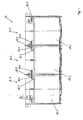
- FIG. 1 shows a battery 10 in a cross-sectional view, which includes galvanic cells 12.1 to 12.6, of which in FIG. 1 the galvanic cells 12.1, 12.2 and 12.3 are shown.
- the galvanic cells 12.1, 12.2, 12.3 each comprise a positive plate set 14.1, 14.2, 14.3 and a negative plate set 16.1, 16.2 and 16.3.
- the galvanic cells 12.1 to 12.3 are spatially and electrically separated from one another by partitions 18.1, 18.2 and arranged in a housing.
- Each of the plate sets 14.1 to 14.3 or 16.1 to 16.3 comprises a plurality of pole plates which are mechanically and electrically connected to a battery cell connection element 20.1, 20.2, 20.3 and 20.4.
- Each two battery cell connecting elements 20.1 and 20.2 or 20.3 and 20.4 are connected by a not-shown opening in the respective partition 18.1 and 18.2 with each other electrically and mechanically connected, so that the galvanic cells 12.1 to 12.3 are connected in series.
- FIG. 2 shows in addition to the galvanic cells 12.1 to 12.3 three more galvanic cells 12.4, 12.5 and 12.6, which are electrically and mechanically connected via two battery cell connection elements 22.1, 22.2 with the galvanic cells 12.1 to 12.3 and connected in series.
- an electric current is applied to a positive terminal 24 and a negative terminal 26, or an electric current is tapped therefrom, the electric current flows through all the galvanic cells 12.1. to 12.6 and thereby passes the battery cell connection elements 20.1 to 20.8 and 22.1, 22.2. Since the electric current has to pass through a plurality of battery cell connecting elements, even small improvements in the electrical resistance exhibited by these battery cell connecting elements result in a relevant reduction in the overall internal resistance of the battery 10.
- FIG. 3a shows a battery cell connector 20 having a connector 28 and a welding tab 30.
- the connector 28 has a substantially cuboidal basic shape with a lower side 32, an upper side 34, a longitudinal side 36 ( FIG. 3b ), a welding side facing away from the longitudinal side 38, a first lateral longitudinal side 40 and a second lateral longitudinal side 42.
- the welding tab 30 is disposed on the welding tab side longitudinal side 36 of the connector 28.
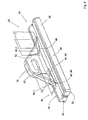
- FIG. 4 shows a perspective view of the battery cell connection element 20 for a battery according to the invention, in which the same objects are provided with the same reference numerals.
- the battery cell connection element 20 comprises a first contact element 44.1 and a second contact element 44.2. Both contact elements 44.1, 44.2 are connected in one piece both with the welding strap 30 and with the connector 28 and taper towards the welding strap 30 in a wedge shape.
- Both contact elements 44.1, 44.2 have a horizontal H-related horizontal cross-sections, which have a decreasing distance to the top 34 increasing surface. In other words, the contact elements 44.1, 44.2 taper upwards.
- the direction "top” as the other orientation information in the present description always refers to a mounting position of the battery cell connection element 20 in a battery 10, as shown in the FIGS. 1 and 2 is shown. However, these directions are not to be understood as limiting, but merely serve to illustrate a particularly suitable arrangement.
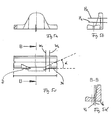
- the contact elements 44.1, 44.2 are also designed such that cuts with a vertical plane V running along the welding-lug-side longitudinal side 36 have a surface which decreases with increasing distance from the welding-lug-side longitudinal side 36.
- the contact elements 44.1, 44.2 are also designed such that a section with a vertical plane W perpendicular to the welding-plate-side longitudinal side W (FIG. FIG. 5c ) has an increasing cross-section with increasing distance from the welding tab 30.
- the contact elements 44.1, 442. thus have a prism-like basic structure whose base is substantially triangular, as in FIG. 5c is indicated by the triangle D.
- the opening angle ⁇ between the two largest legs is between 30 ° and 60 °, wherein one of the legs extends parallel to the welding plate side longitudinal side 36.
- FIG. 4 shows a connector-side transition region 46 that includes a lateral portion 48 and a medial portion 50.
- the transition region has a lateral radius of curvature of 3 mm to 10 mm and in the medial section 50 a medial radius of curvature is 2 mm.
- a radius of curvature of also 2 mm is present.
- the battery cell connector 20 is manufactured by pouring lead into a suitably shaped mold. To the resulting battery cell connector easy to remove from the mold, run the welding tab 30, the connector 28 and the contact elements 44.1, 44.2 conically upwards and form with their respective surfaces relative to a corresponding vertical plane an angle of 2 ° to 7 °.
Landscapes
- Chemical & Material Sciences (AREA)
- Chemical Kinetics & Catalysis (AREA)
- Electrochemistry (AREA)
- General Chemical & Material Sciences (AREA)
- Connection Of Batteries Or Terminals (AREA)
- Battery Mounting, Suspending (AREA)
Description
- Die Erfindung betrifft eine Batterie mit mindestens einem Batteriezellenverbindungselement, das (a) einen eine quaderförmige Grundgestalt aufweisenden Verbinder zum Verbinden mit mindestens einer Platte, insbesondere mit einem Polplattensatz, an einer Unterseite des Verbinders und (b) eine Schweißlasche, die mit einem Verbinder elektrisch leitend verbunden ist, umfasst, (c) wobei in Einbaulage der Batterie der Verbinder im Wesentlichen horizontal verläuft und die Schweißlasche im Wesentlichen vertikal verläuft, und (d) wobei der Verbinder eine der Unterseite gegenüber liegende Oberseite und (e) mindestens eine an die Unterseite angrenzende Längsseite besitzt, an der die Schweißlasche mit dem Verbinder verbunden ist.
- Eine solche Batterie ist beispielsweise aus der
DE 103 23 529 B3 oder aus derDE 24 47 639 bekannt. - Derartige Batterien in Form von Bleiakkumulatoren werden beispielsweise als Starterbatterie in einem Automobil verwendet. Eine derartige Batterie besteht aus mehreren galvanischen Zellen, die in Reihe geschaltet und voneinander durch eine elektrisch isolierende Trennwand getrennt sind. Jede der galvanischen Zellen umfasst einen positiven und einen negativen Plattensatz, die beide jeweils aus mehreren Polplatten aufgebaut sind. Ein Batteriezellenverbindungselement verbindet die Polplatten eines Plattensatzes untereinander elektrisch und mechanisch und dient zusätzlich dazu, den Plattensatz einer galvanischen Zelle über ein weiteres Batteriezellenverbindungselement mit einem anderen Plattensatz einer anderen galvanischen Zelle durch die Trennwand hindurch elektrisch zu verkontaktieren. Ein Verbindungselement zur Verbindung von Zellen zu Akkumulatoren ist aus der
EP 1 691 431 A1 bekannt. - Um einen solchen elektrischen Kontakt zu ermöglichen, werden bei der Fertigung der Batterien die Batterieverbindungselemente relativ zueinander und relativ zu einer Ausnehmung in der Trennwand ausgerichtet. Anschließend werden die Schweißlaschen zweier beidseits der Trennwand angeordneter Batteriezellenverbindungselemente miteinander verschweißt und so elektrisch miteinander verbunden.
- Bei Bleiakkumulatoren besteht der Verbinder in der Regel vollständig aus Blei, das für ein Metall eine relativ geringe elektrische Leitfähigkeit hat. Bleiakkumulatoren weisen in der Regel nur Spannungen zwischen 6 Volt und 48 Volt auf. In modernen Kraftfahrzeugen wie Nutzkraftwagen werden jedoch hohe Leistungen bis zu mehreren Kilowatt benötigt, so dass unter Last große Ströme durch die Batteriezellenverbindungselemente fließen. Bei derartigen Strömen kommt es aufgrund des Innenwiderstands der Batterie zu einer unerwünschten Erwärmung, was nachteilig ist. Der Innenwiderstand der Batterie begrenzt zudem nachteiligerweise die maximale Leistung, die von der Batterie abgegeben werden kann.
- Der Erfindung liegt die Aufgabe zugrunde, eine Batterie mit verringertem Innenwiderstand bereitzustellen.
- Die Erfindung löst das Problem durch eine gattungsgemäße Batterie, bei der die Schweißlasche über mindestens ein lateral an der Schweißlasche angeordnetes und auf die Oberfläche des Verbinders führendes Kontaktelement mit dem Verbinder elektrisch verbunden ist.
- Durch eine Batterie mit einem derartigen Batteriezellenverbindungselement wird vorteilhafterweise erreicht, dass ein elektrischer Strom, der von den Polplatten über das Batteriezellenverbindungselement fließt, einen geringeren elektrischen Widerstand erfährt als wenn das Batteriezellenverbindungselement mit der gleichen Menge an Material ohne das Kontaktelement hergestellt wäre. Durch das Kontaktelement wird das für die elektrische Leitung des Stroms zur Verfügung stehende Material des Batteriezellenverbindungselementes optimal für den Stromfluss genutzt, so dass ein reduzierter Innenwiderstand der Batterie erreichbar ist. Das reduziert die unerwünschte Erwärmung der Batterie während des Betriebs und ermöglicht eine höhere Leistungsabgabe der Batterie.
- Ist ein maximal akzeptabler Innenwiderstand vorgegeben, so ermöglicht die Erfindung alternativ die Einsparung an Material für die Herstellung des Batteriezellenverbindungselements, beispielsweise von Blei.
- Vorteilhaft ist zudem, dass die Erfindung mit geringem Aufwand umsetzbar ist. So müssen lediglich die Formen ausgetauscht werden, mit deren Hilfe die Batteriezellenverbindungselemente gegossen werden.
- Im Rahmen der vorliegenden Erfindung wird unter einer quaderförmigen Grundgestalt verstanden, dass es möglich, nicht aber notwendig ist, dass der Verbinder im strengen mathematischen Sinn quaderförmig ausgebildet ist. Es ist vielmehr möglich, dass der Verbinder von der quaderförmigen Gestalt abweicht, indem beispielsweise mehr als sechs Flächen vorhanden sind, zwei gegenüberliegende Seiten nicht parallel zueinander verlaufen oder aneinander angrenzende Flächen unter einem anderen als einem rechten Winkel zueinander verlaufen. Derartige Modifikationen sind aus dem Stand der Technik bekannt.
- Unter dem Merkmal, dass der Verbinder im Wesentlichen horizontal verläuft, ist zu verstehen, dass es möglich, nicht aber notwendig ist, dass der Verbinder streng horizontal verläuft. Es ist insbesondere ausreichend, wenn der Verbinder unter einem Winkel von weniger als 10° zur Horizontalen verläuft. Entsprechendes gilt für das Merkmal, dass die Schweißlasche im Wesentlichen vertikal verläuft. Auch hier werden Abweichungen von beispielsweise weniger als 10° von der Vertikalen als im Wesentlichen vertikal betrachtet.
- In einer bevorzugten Ausführungsform ist die Batterie ein Bleiakkumulator, insbesondere ein Nutzkraftwagen-Bleiakkumulator. Nutzkraftwagen-Bleiakkumulatoren unterscheiden sich beispielsweise von Personenkraftwagen- oder Motorrad-Bleiakkumulatoren dadurch, dass die Schweißlasche zentrisch an der Längsseite des Verbinders angeordnet ist.
- Es ist bevorzugt, dass die Schweißlasche zwei Kontaktelemente aufweist, die beidseits lateral an der Schweißlasche angeordnet sind, auf die Oberfläche des Verbinders führen und die Schweißlasche mit dem Verbinder elektrisch verbinden. Dabei sind die Kontaktelemente beispielsweise spiegelsymmetrisch zueinander aufgebaut, so dass das Batteriezellenverbindungselement ebenfalls spiegelsymmetrisch zu einer Spiegelebene aufgebaut ist.
- Mit zunehmendem Abstand von der Oberseite des Verbinders sinkt bei einem Laden bzw. Entladen der Batterien die Stromdichte, weshalb bevorzugt vorgesehen ist, dass das Kontaktelement einen Querschnitt aufweist, der mit abnehmendem Abstand von der Oberseite des Verbinders zunimmt. Vorteilhaft ist daran zudem, dass sich das Batteriezellenverbindungselement so besonders leicht aus einer Gussform entfernen lässt.
- Da ein elektrischer Strom, der von einer Polplatte stammt, die an einem äußeren Ende des Verbinders mit dem Verbinder verbunden ist, einen besonders hohen elektrischen Widerstand zu überwinden hat, ist in einer bevorzugten Ausführungsform vorgesehen, dass das Kontaktelement einen Querschnitt aufweist, der mit zunehmendem Abstand von der Schweißlasche zunimmt. Auf diese Weise wird der elektrische Widerstand verringert, den Strom von einer seitlich liegenden Polplatte überwinden muss.
- Es ist bevorzugt, dass das Kontaktelement einen verbinderseitigen Übergangsbereich besitzt, in dem es in den Verbinder übergeht, dass der verbinderseitige Übergangsbereich einen lateralen Abschnitt besitzt und der laterale Abschnitt einen Lateral-Krümmungsradius aufweist, der zwischen 3 mm und 10 mm liegt. Es hat sich gezeigt, dass auf diese Weise ein besonders geringer Innenwiderstand der Batterie möglich ist. Das Adjektiv "lateral" bezieht sich dabei auf das Batteriezellenverbindungselement und bedeutet der Schweißlasche abgewandt.
- Das Kontaktelement besitzt zudem vorteilhafterweise einen medialen Abschnitt, der einen Medial-Krümmungsradius aufweist, der zwischen 1 mm und 3 mm liegt. In einem schweißlaschenseitigen Übergangsbereich, in dem das Kontaktelement in die Schweißlasche übergeht, besitzt es günstigerweise einen Krümmungsradius zwischen 0,25 mm und 2 mm.
- Zur Vereinfachung der Fertigung ist das Batteriezellenverbindungselement bevorzugt einstückig ausgebildet, insbesondere ist es aus Blei gegossen. Ein besonders geringer Innenwiderstand für das Batteriezellenverbindungselement ergibt sich, wenn ein auf die Oberseite projizierter Kontaktelement-Querschnitt des Kontaktelements eine Seitenlinie besitzt, die unter einem Winkel von 30° bis 60° zu der Längsachse des Verbinders verläuft. Günstig ist es, wenn der Kontaktelement-Querschnitt im Wesentlichen dreieckig ist, wobei eine weitere Seite des Kontaktelement-Querschnitts im Wesentlichen parallel zu der Längsseite des Verbinders verläuft. Der Winkel zwischen den beiden langen Seiten des Kontaktelement-Querschnitts, der seinen Scheitelpunkt innerhalb der Schweißlasche hat, beträgt dann ebenfalls 30° bis 60°.
- Eine Materialeinsparung ergibt sich, wenn der Kontaktelement-Querschnitt dort, wo das Kontaktelement in den Verbinder übergeht, eine Kontaktelement-Querschnittsfläche besitzt, die kleiner ist als ein horizontaler Querschnitt der Schweißlasche auf gleicher Höhe. So ist auf jeder horizontalen Höhe der Querschnitt der Schweißlasche größer als der des Kontaktelements. Unter der Größe des Querschnitts wird dabei die Querschnittsfläche verstanden. Besonders günstig ist es, wenn der Kontaktelement-Querschnitt kleiner ist als die Hälfte des Querschnitts der Schweißlasche auf gleicher horizontaler Höhe.
- Die Montage des Batteriezellenverbindungselementes wird besonders erleichtert, wenn das Kontaktelement verbinderseitig im Wesentlichen vollständig jenseits einer horizontalen Ebene angeordnet ist, die durch die Längsseite verläuft, an der die Schweißlasche mit dem Verbinder verbunden ist.
- Im Folgenden wird eine Ausführungsform der Erfindung anhand der Zeichnungen näher erläutert. Dabei zeigt
- Figur 1
- einen Querschnitt durch eine erfindungsgemäße Batterie,
- Figur 2
- eine Draufsicht auf die Batterien gemäß
Figur 1 , - Figuren 3a, 3b, 3c
- zeigen Querschnittsansichten von Batteriezellenverbindungselementen gemäß dem Stand der Technik,
- Figur 4
- zeigt ein Batteriezellenverbindungselement für eine erfindungsgemäße Batterie und die
- Figuren 5a, 5b, 5c, 5d
- zeigen Querschnittsansichten eines Batteriezellenverbindungselements einer erfindungsgemäßen Batterie.
-
Figur 1 zeigt eine Batterie 10 in einer Querschnittsansicht, die galvanische Zellen 12.1 bis 12.6 umfasst, von denen inFigur 1 die galvanischen Zellen 12.1, 12.2 und 12.3 gezeigt sind. Die galvanischen Zellen 12.1, 12.2, 12.3 umfassen jeweils einen positiven Plattensatz 14.1, 14.2, 14.3 und einen negativen Plattensatz 16.1, 16.2 und 16.3. Die galvanischen Zellen 12.1 bis 12.3 sind durch Trennwände 18.1, 18.2 voneinander räumlich und elektrisch getrennt und in einem Gehäuse angeordnet. - Jeder der Plattensätze 14.1 bis 14.3 bzw. 16.1 bis 16.3 umfasst mehrere Polplatten, die mechanisch und elektrisch mit einem Batteriezellenverbindungselement 20.1, 20.2, 20.3 bzw. 20.4 verbunden sind. Jeweils zwei Batteriezellenverbindungselemente 20.1 und 20.2 bzw. 20.3 und 20.4 sind durch eine nicht eingezeichnete Öffnung in der jeweiligen Trennwand 18.1 bzw. 18.2 miteinander elektrisch und mechanisch verbunden, so dass die galvanischen Zellen 12.1 bis 12.3 in Reihe geschaltet sind.
-
Figur 2 zeigt neben den galvanischen Zellen 12.1 bis 12.3 drei weitere galvanische Zellen 12.4, 12.5 und 12.6, die über zwei Batteriezellenverbindungselemente 22.1, 22.2 mit den galvanischen Zellen 12.1 bis 12.3 elektrisch und mechanisch verbunden und in Reihe geschaltet sind. Wenn an einen Pluspol 24 und an einen Minuspol 26 ein elektrischer Strom angelegt oder von diesen ein elektrischer Strom abgegriffen wird, so fließt der elektrische Strom durch alle galvanischen Zellen 12.1. bis 12.6 und passiert dabei die Batteriezellenverbindungselemente 20.1 bis 20.8 und 22.1, 22.2. Da der elektrische Strom durch eine Vielzahl Batteriezellenverbindungselemente treten muss, führen selbst kleine Verbesserungen hinsichtlich des elektrischen Widerstands, den diese Batteriezellenverbindungselemente aufweisen, zu einer relevanten Verminderung des Gesamt-Innenwiderstandes der Batterie 10. -
Figur 3a zeigt ein Batteriezellenverbindungselement 20, das einen Verbinder 28 und eine Schweißlasche 30 besitzt. Der Verbinder 28 besitzt eine im Wesentlichen quaderförmige Grundgestalt mit einer Unterseite 32, einer Oberseite 34, einer schweißlaschenseitigen Längsseite 36 (Figur 3b ), einer schweißlaschenabgewandten Längsseite 38, einer ersten lateralen Längsseite 40 und einer zweiten lateralen Längsseite 42. Die Schweißlasche 30 ist an der schweißlaschenseitigen Längsseite 36 des Verbinders 28 angeordnet. -
Figur 4 zeigt eine perspektivische Ansicht des Batteriezellenverbindungselements 20 für eine erfindungsgemäße Batterie, bei dem gleiche Objekte mit den gleichen Bezugszeichen versehen sind. Das Batteriezellenverbindungselement 20 umfasst ein erstes Kontaktelement 44.1 und ein zweites Kontaktelement 44.2. Beide Kontaktelemente 44.1, 44.2 sind sowohl mit der Schweißlasche 30 als auch mit dem Verbinder 28 einstückig verbunden und laufen keilförmig sich verjüngend auf die Schweißlasche 30 zu. - Beide Kontaktelemente 44.1, 44.2 weisen auf eine Horizontale H bezogene horizontale Querschnitte auf, die eine mit abnehmendem Abstand zu der Oberseite 34 zunehmende Fläche besitzen. In anderen Worten verjüngen sich die Kontaktelemente 44.1, 44.2 nach oben. Die Richtung "oben" bezieht sich wie die sonstigen Orientierungsangaben in der vorliegenden Beschreibung stets auf eine Einbaulage des Batteriezellenverbindungselements 20 in einer Batterie 10, wie sie in den
Figuren 1 und2 gezeigt ist. diese Orientierungsangaben sind jedoch nicht einschränkend zu verstehen, sondern dienen lediglich der Verdeutlichung einer besonders geeigneten Anordnung. - Die Kontaktelemente 44.1, 44.2 sind zudem so ausgebildet, dass Schnitte mit einer entlang der schweißlaschenseitigen Längsseite 36 verlaufenden Vertikalebene V eine Fläche besitzen, die mit zunehmendem Abstand von der schweißlaschenseitigen Längsseite 36 abnimmt. Die Kontaktelemente 44.1, 44.2 sind zudem so ausgebildet, dass ein Schnitt mit einer senkrecht zu der schweißlaschenseitigen Längsseite 36 verlaufenden vertikalen Ebene W (
Figur 5c ) einen mit zunehmendem Abstand von der Schweißlasche 30 zunehmenden Querschnitt besitzt. Die Kontaktelemente 44.1, 442. haben damit eine prismenartige Grundstruktur, deren Grundfläche im Wesentlichen dreieckig ist, wie inFigur 5c durch das Dreieck D angedeutet ist. Der Öffnungswinkel α zwischen den beiden größten Schenkeln liegt zwischen 30° und 60°, wobei einer der Schenkel parallel zu der schweißlaschenseitigen Längsseite 36 verläuft. -
Figur 4 zeigt einen verbinderseitigen Übergangsbereich 46, der einen lateralen Abschnitt 48 und einen medialen Abschnitt 50 umfasst. Im lateralen Abschnitt 48 besitzt der Übergangsbereich einen Lateral-Krümmungsradius von 3 mm bis 10 mm und im medialen Abschnitt 50 beträgt ein Medial-Krümmungsradius 2 mm. In einem schweißlaschenseitigen Übergangsbereich 52 liegt ein Krümmungsradius von ebenfalls 2 mm vor. - Das Batteriezellenverbindungselement 20 wird hergestellt, indem Blei in eine geeignet geformte Form gegossen wird. Um das entstandene Batteriezellenverbindungselement leicht entformen zu können, laufen die Schweißlasche 30, der Verbinder 28 und die Kontaktelemente 44.1, 44.2 nach oben hin konisch zu und bilden dabei mit ihren entsprechenden Flächen relativ zu einer entsprechenden vertikalen Ebene einen Winkel von 2° bis 7°.
-
- 10
- Batterie
- 12.1, ..., 12.6
- galvanische Zelle
- 14.1, 14.2, 14.3
- positiver Plattensatz
- 16.1, 16.2, 16.3
- negativer Plattensatz
- 18.1, 18.2
- Trennwand
- 20.1., 20.2, ..., 20.8 22.1, 22.2
- Batteriezellenverbindungselement
- 24
- Pluspol
- 26
- Minuspol
- 28
- Verbinder
- 30
- Schweißlasche
- 32
- Unterseite
- 34
- Oberseite
- 36
- schweißlaschenseitige Längsseite
- 38
- schweißlaschenabgewandte Längsseite
- 40
- erste laterale Längsseite
- 42
- zweite laterale Längsseite
- 44.1, 44.2
- Kontaktelement
- 46
- verbinderseitiger Übergangsbereich
- 48
- lateraler Abschnitt
- 50
- medialer Abschnitt
- 52
- schweißlaschenseitiger Übergangsbereich
- V
- vertikale Ebene
- H
- horizontale Ebene
- S
- Seitenlinie
- α
- Öffnungswinkel
Claims (14)
- Batterie mit mindestens einem Batteriezellenverbindungselement (20), das(a) einen eine quaderförmige Grundgestalt aufweisenden Verbinder (28) zum Verbinden mit mindestens einer Polplatte an einer Unterseite (32) des Verbinders (28) und(b) eine Schweißlasche (30), die mit dem Verbinder (28) elektrisch leitend verbunden ist, umfasst,(c) wobei in Einbaulage der Batterie (10)
der Verbinder (28) im Wesentlichen horizontal angeordnet ist und die Schweißlasche (30) im Wesentlichen vertikal angeordnet ist, und(d) wobei der Verbinder (28) eine der Unterseite (32) gegenüber liegende Oberseite (34) und(e) mindestens eine an die Unterseite (32) angrenzende Längsseite (36) besitzt, an der die Schweißlasche (30) mit dem Verbinder (28) verbunden ist,
dadurch gekennzeichnet, dass(f) die Schweißlasche (30) über mindestens ein lateral an der Schweißlasche (30) angeordnetes und auf die Oberfläche des Verbinders (28) führendes Kontaktelement (44.1, 44.2) mit dem Verbinder (28) elektrisch verbunden ist. - Batterie nach Anspruch 1, dadurch gekennzeichnet, dass sie ein Bleiakkumulator (10), insbesondere ein Nutzkraftwagen-Bleiakkumulator, ist.
- Batterie nach einem der vorstehenden Ansprüche, dadurch gekennzeichnet, dass die Schweißlasche (30) über zwei lateral an der Schweißlasche (30) angeordnete und auf die Oberfläche des Verbinders (28) führende Kontaktelemente (44.1, 44.2) mit dem Verbinder elektrisch verbunden ist.
- Batterie nach einem der vorstehenden Ansprüche, dadurch gekennzeichnet, dass das Kontaktelement (44.1, 44.2) einen Querschnitt aufweist, der mit abnehmendem Abstand von der Oberseite (34) des Verbinders (28) zunimmt.
- Batterie nach einem der vorstehenden Ansprüche, dadurch gekennzeichnet, dass das Kontaktelement (44) einen Querschnitt aufweist, der mit zunehmendem Abstand von der Schweißlasche (30) zunimmt.
- Batterie nach einem der vorstehenden Ansprüche, dadurch gekennzeichnet, dass- das Kontaktelement (44) einen verbinderseitigen Übergangsbereich (46) besitzt, in dem es in den Verbinder (28) übergeht,- der verbinderseitige Übergangsbereich (46) einen lateralen Abschnitt (48) besitzt und- der laterale Abschnitt (48) einen Lateral-Krümmungsradius aufweist, der zwischen 3 mm und 10 mm liegt.
- Batterie nach einem der vorstehenden Ansprüche, dadurch gekennzeichnet,
dass- das Kontaktelement (44) einen verbinderseitigen Übergangsbereich (46) besitzt, in dem es in den Verbinder übergeht,- der verbinderseitige Übergangsbereich (46) einen medialen Abschnitt (50) besitzt undder mediale Abschnitt (50) einen Medial-Krümmungsradius aufweist, der zwischen 1 mm und 3 mm liegt. - Batterie nach einem der vorstehenden Ansprüche, dadurch gekennzeichnet, dass das Kontaktelement (44) in einem schweißlaschenseitigen Übergangsbereich (52), in dem es in die Schweißlasche (30) übergeht, einen Krümmungsradius aufweist, der zwischen 0,25 mm und 2 mm liegt.
- Batterie nach einem der vorstehenden Ansprüche, dadurch gekennzeichnet, dass das Batteriezellenverbindungselement (20) einstückig ausgebildet ist.
- Batterie nach Anspruch 9, dadurch gekennzeichnet, dass das Batteriezellenverbindungselement (20) ein Gussstück, insbesondere aus Blei, ist.
- Batterie nach einem der vorstehenden Ansprüche, dadurch gekennzeichnet, dass ein auf die Oberseite (34) projizierter Kontaktelement-Querschnitt (D) des Kontaktelements eine Seitenlinie (S) besitzt, die unter einem Winkel (α) von 30° bis 60° zu der Längsseite (36) des Verbinders (28) verläuft.
- Batterie nach einem der vorstehenden Ansprüche, dadurch gekennzeichnet, dass der Kontaktelement-Querschnitt (D) dort, wo das Kontaktelement (44) in den Verbinder (28) übergeht, kleiner ist als ein horizontaler Querschnitt der Schweißlasche (30).
- Batterie nach einem der vorstehenden Ansprüche, dadurch gekennzeichnet, dass das Kontaktelement (44.1, 44.2) verbinderseitig im Wesentlichen jenseits einer horizontalen Ebene angeordnet ist, die durch die Längsseite (36) verläuft, an der die Schweißlasche (30) mit dem Verbinder (28) verbunden ist.
- Batterie nach einem der vorstehenden Ansprüche, dadurch gekennzeichnet, dass die Schweißlasche (30) einen mit zunehmendem Abstand von dem Verbinder (28) abnehmenden Querschnitt aufweist, so einander gegenüber liegende Seitenflächen der Schweißlaschen (30) einen Winkel von 2° bis 10° zueinander aufweisen.
Priority Applications (1)
| Application Number | Priority Date | Filing Date | Title |
|---|---|---|---|
| PL08734346T PL2132808T3 (pl) | 2007-03-07 | 2008-03-03 | Bateria |
Applications Claiming Priority (2)
| Application Number | Priority Date | Filing Date | Title |
|---|---|---|---|
| DE102007011390A DE102007011390B4 (de) | 2007-03-07 | 2007-03-07 | Batterie |
| PCT/DE2008/000372 WO2008106945A2 (de) | 2007-03-07 | 2008-03-03 | Batterie |
Publications (2)
| Publication Number | Publication Date |
|---|---|
| EP2132808A2 EP2132808A2 (de) | 2009-12-16 |
| EP2132808B1 true EP2132808B1 (de) | 2013-04-24 |
Family
ID=39687991
Family Applications (1)
| Application Number | Title | Priority Date | Filing Date |
|---|---|---|---|
| EP08734346.3A Active EP2132808B1 (de) | 2007-03-07 | 2008-03-03 | Batterie |
Country Status (8)
| Country | Link |
|---|---|
| US (1) | US8431268B2 (de) |
| EP (1) | EP2132808B1 (de) |
| CN (1) | CN101730951B (de) |
| BR (1) | BRPI0808426B1 (de) |
| DE (1) | DE102007011390B4 (de) |
| ES (1) | ES2424168T3 (de) |
| PL (1) | PL2132808T3 (de) |
| WO (1) | WO2008106945A2 (de) |
Families Citing this family (4)
| Publication number | Priority date | Publication date | Assignee | Title |
|---|---|---|---|---|
| JP4462245B2 (ja) * | 2006-07-19 | 2010-05-12 | トヨタ自動車株式会社 | 2次電池、積層2次電池および組電池 |
| DE102009014116B3 (de) * | 2009-03-24 | 2010-09-23 | Vb Autobatterie Gmbh & Co. Kgaa | Batteriezellenverbinder und Batterie |
| DE102011120237B4 (de) * | 2011-12-05 | 2021-09-02 | Audi Ag | Verbindungselement zum elektrischen Verbinden von parallel geschalteten Batteriezellen, Batterie und Verfahren zum Herstellen eines Verbindungselements |
| DE102021125014A1 (de) | 2021-09-28 | 2023-03-30 | Bayerische Motoren Werke Aktiengesellschaft | Batteriezellengehäuse für eine Batteriezelle eines elektrischen Energiespeichers, Batteriezelle, elektrischer Energiespeicher sowie Verfahren |
Family Cites Families (8)
| Publication number | Priority date | Publication date | Assignee | Title |
|---|---|---|---|---|
| DE2447639C3 (de) * | 1974-10-05 | 1978-08-24 | Accumulatorenwerk Hoppecke Carl Zoellner & Sohn, 5000 Koeln | Zellenverbindung eines Bleiakkumulators |
| JPH0294254A (ja) * | 1988-09-29 | 1990-04-05 | Aisin Seiki Co Ltd | 蓄電池 |
| US5308719A (en) * | 1992-09-21 | 1994-05-03 | Globe-Union Inc. | Lead acid batteries containing center lug plates and high performance cast-on straps |
| JP3168834B2 (ja) * | 1994-07-13 | 2001-05-21 | 新神戸電機株式会社 | 鉛蓄電池の群溶接方法 |
| JPH08130030A (ja) * | 1994-10-27 | 1996-05-21 | Furukawa Battery Co Ltd:The | 鉛蓄電池 |
| US6225006B1 (en) * | 1999-07-15 | 2001-05-01 | Gnb Technologies, Inc. | Family of lead-acid batteries using a standardized container and having voltage that can be preselected as necessary |
| DE10323529B3 (de) * | 2003-05-24 | 2004-08-26 | Varta Automotive Systems Gmbh | Zellenverbindereinheit und Verfahren zur elektrischen Verbindung von benachbarten Zellen |
| EP1691431A1 (de) * | 2005-02-14 | 2006-08-16 | SAT Akkumulatoren Technik AG | Verbindungselement zur Verbindung von Zellen zu Akkumulatoren |
-
2007
- 2007-03-07 DE DE102007011390A patent/DE102007011390B4/de not_active Expired - Fee Related
-
2008
- 2008-03-03 EP EP08734346.3A patent/EP2132808B1/de active Active
- 2008-03-03 CN CN2008800140423A patent/CN101730951B/zh active Active
- 2008-03-03 ES ES08734346T patent/ES2424168T3/es active Active
- 2008-03-03 WO PCT/DE2008/000372 patent/WO2008106945A2/de not_active Ceased
- 2008-03-03 BR BRPI0808426-2A patent/BRPI0808426B1/pt active IP Right Grant
- 2008-03-03 PL PL08734346T patent/PL2132808T3/pl unknown
- 2008-03-03 US US12/529,931 patent/US8431268B2/en active Active
Also Published As
| Publication number | Publication date |
|---|---|
| CN101730951A (zh) | 2010-06-09 |
| ES2424168T3 (es) | 2013-09-27 |
| WO2008106945A2 (de) | 2008-09-12 |
| PL2132808T3 (pl) | 2014-01-31 |
| DE102007011390B4 (de) | 2011-06-09 |
| WO2008106945A3 (de) | 2010-01-14 |
| US20100183921A1 (en) | 2010-07-22 |
| DE102007011390A1 (de) | 2008-09-18 |
| EP2132808A2 (de) | 2009-12-16 |
| CN101730951B (zh) | 2013-02-13 |
| BRPI0808426A2 (pt) | 2014-07-22 |
| BRPI0808426B1 (pt) | 2019-11-05 |
| US8431268B2 (en) | 2013-04-30 |
Similar Documents
| Publication | Publication Date | Title |
|---|---|---|
| DE60032434T2 (de) | Polenstruktur einer modularen Batterie | |
| DE102021125167B4 (de) | Batteriemodul | |
| DE102014118773B4 (de) | Traktionsbatterie-baugruppe | |
| DE112018003895T5 (de) | Energiespeichereinrichtung | |
| DE102007063185A1 (de) | Batterie | |
| DE2206013A1 (de) | Elektrische Batterie für Automobile od. dgl | |
| DE102022103728B3 (de) | Batteriezelle | |
| EP2080240B1 (de) | Batterie und verfahren zum herstellen einer batterie | |
| DE102011081307A1 (de) | Elektrischer Verteilerkasten | |
| DE102007011390B4 (de) | Batterie | |
| WO2015074735A1 (de) | Batterie mit einer mehrzahl von batteriezellen wobei die pole mittels verbindungselemente verbunden sind | |
| EP2400581B1 (de) | Montageeinrichtung für Batteriezellen | |
| DE102007022246B4 (de) | Batterie | |
| DE112017006651T5 (de) | Energiespeichervorrichtung | |
| WO2013107552A1 (de) | Energiemodul für einen elektrischen energiespeicher für ein fahrzeug und verfahren zur herstellung des energiemoduls | |
| DE102009038422B4 (de) | Kraftwagen | |
| WO2020099535A1 (de) | Deckel für ein batteriemodul, batteriemodulanordnung und batterie | |
| EP3935692B1 (de) | Versetzte polbuchsen und energiespeichersystem mit den gleichen | |
| DE102018204373A1 (de) | Zellverbinder für ein Batteriemodul einer Hochvoltbatterie eines Kraftfahrzeugs, Batteriemodul, Kraftfahrzeug sowie Verfahren zum Herstellen eines Batteriemoduls | |
| DE102022124988B4 (de) | Sammel-Verbindungsschiene mit Kopplungsabschnitten zur körperlichen Kopplung mehrerer gleichartiger Sammel-Verbindungsschienen | |
| WO2014198925A1 (de) | Akkumulator und verfahren zur herstellung eines akkumulators | |
| DE102025122900A1 (de) | Batteriezellen-flachsteckeranschlusskonfigurationen | |
| DE102016114856A1 (de) | Verbindungselement für einen Batteriekasten sowie Batteriebaukasten und Verfahren zu seiner Herstellung | |
| EP2820695B1 (de) | Batterie mit einem verbindungselement zum elektrischen verbinden von parallel geschalteten batteriezellen | |
| DE102024000259A1 (de) | Zellgehäuse, Batteriezelle, Batteriemodul und Batterie |
Legal Events
| Date | Code | Title | Description |
|---|---|---|---|
| PUAI | Public reference made under article 153(3) epc to a published international application that has entered the european phase |
Free format text: ORIGINAL CODE: 0009012 |
|
| 17P | Request for examination filed |
Effective date: 20090918 |
|
| AK | Designated contracting states |
Kind code of ref document: A2 Designated state(s): AT BE BG CH CY CZ DE DK EE ES FI FR GB GR HR HU IE IS IT LI LT LU LV MC MT NL NO PL PT RO SE SI SK TR |
|
| R17D | Deferred search report published (corrected) |
Effective date: 20100114 |
|
| DAX | Request for extension of the european patent (deleted) | ||
| GRAP | Despatch of communication of intention to grant a patent |
Free format text: ORIGINAL CODE: EPIDOSNIGR1 |
|
| GRAS | Grant fee paid |
Free format text: ORIGINAL CODE: EPIDOSNIGR3 |
|
| GRAA | (expected) grant |
Free format text: ORIGINAL CODE: 0009210 |
|
| AK | Designated contracting states |
Kind code of ref document: B1 Designated state(s): AT BE BG CH CY CZ DE DK EE ES FI FR GB GR HR HU IE IS IT LI LT LU LV MC MT NL NO PL PT RO SE SI SK TR |
|
| REG | Reference to a national code |
Ref country code: GB Ref legal event code: FG4D Free format text: NOT ENGLISH |
|
| REG | Reference to a national code |
Ref country code: CH Ref legal event code: EP |
|
| REG | Reference to a national code |
Ref country code: AT Ref legal event code: REF Ref document number: 609092 Country of ref document: AT Kind code of ref document: T Effective date: 20130515 |
|
| REG | Reference to a national code |
Ref country code: IE Ref legal event code: FG4D Free format text: LANGUAGE OF EP DOCUMENT: GERMAN |
|
| REG | Reference to a national code |
Ref country code: DE Ref legal event code: R096 Ref document number: 502008009778 Country of ref document: DE Effective date: 20130620 |
|
| REG | Reference to a national code |
Ref country code: RO Ref legal event code: EPE |
|
| REG | Reference to a national code |
Ref country code: AT Ref legal event code: HC Ref document number: 609092 Country of ref document: AT Kind code of ref document: T Owner name: JOHNSON CONTROLS AUTOBATTERIE GMBH & CO. KGAA, DE Effective date: 20130813 |
|
| REG | Reference to a national code |
Ref country code: DE Ref legal event code: R082 Ref document number: 502008009778 Country of ref document: DE Representative=s name: GRAMM, LINS & PARTNER GBR, DE Ref country code: LT Ref legal event code: MG4D |
|
| REG | Reference to a national code |
Ref country code: ES Ref legal event code: FG2A Ref document number: 2424168 Country of ref document: ES Kind code of ref document: T3 Effective date: 20130927 |
|
| RAP2 | Party data changed (patent owner data changed or rights of a patent transferred) |
Owner name: JOHNSON CONTROLS AUTOBATTERIE GMBH & CO. KGAA |
|
| REG | Reference to a national code |
Ref country code: NL Ref legal event code: VDEP Effective date: 20130424 |
|
| PG25 | Lapsed in a contracting state [announced via postgrant information from national office to epo] |
Ref country code: SI Free format text: LAPSE BECAUSE OF FAILURE TO SUBMIT A TRANSLATION OF THE DESCRIPTION OR TO PAY THE FEE WITHIN THE PRESCRIBED TIME-LIMIT Effective date: 20130424 Ref country code: PT Free format text: LAPSE BECAUSE OF FAILURE TO SUBMIT A TRANSLATION OF THE DESCRIPTION OR TO PAY THE FEE WITHIN THE PRESCRIBED TIME-LIMIT Effective date: 20130826 Ref country code: LT Free format text: LAPSE BECAUSE OF FAILURE TO SUBMIT A TRANSLATION OF THE DESCRIPTION OR TO PAY THE FEE WITHIN THE PRESCRIBED TIME-LIMIT Effective date: 20130424 Ref country code: SE Free format text: LAPSE BECAUSE OF FAILURE TO SUBMIT A TRANSLATION OF THE DESCRIPTION OR TO PAY THE FEE WITHIN THE PRESCRIBED TIME-LIMIT Effective date: 20130424 Ref country code: FI Free format text: LAPSE BECAUSE OF FAILURE TO SUBMIT A TRANSLATION OF THE DESCRIPTION OR TO PAY THE FEE WITHIN THE PRESCRIBED TIME-LIMIT Effective date: 20130424 Ref country code: GR Free format text: LAPSE BECAUSE OF FAILURE TO SUBMIT A TRANSLATION OF THE DESCRIPTION OR TO PAY THE FEE WITHIN THE PRESCRIBED TIME-LIMIT Effective date: 20130725 Ref country code: NO Free format text: LAPSE BECAUSE OF FAILURE TO SUBMIT A TRANSLATION OF THE DESCRIPTION OR TO PAY THE FEE WITHIN THE PRESCRIBED TIME-LIMIT Effective date: 20130724 Ref country code: IS Free format text: LAPSE BECAUSE OF FAILURE TO SUBMIT A TRANSLATION OF THE DESCRIPTION OR TO PAY THE FEE WITHIN THE PRESCRIBED TIME-LIMIT Effective date: 20130824 |
|
| REG | Reference to a national code |
Ref country code: DE Ref legal event code: R081 Ref document number: 502008009778 Country of ref document: DE Owner name: JOHNSON CONTROLS AUTOBATTERIE GMBH & CO. KGAA, DE Free format text: FORMER OWNER: VB AUTOBATTERIE GMBH & CO. KGAA, 30419 HANNOVER, DE Effective date: 20130925 Ref country code: DE Ref legal event code: R082 Ref document number: 502008009778 Country of ref document: DE Representative=s name: GRAMM, LINS & PARTNER GBR, DE Effective date: 20130925 Ref country code: DE Ref legal event code: R082 Ref document number: 502008009778 Country of ref document: DE Representative=s name: MEISSNER, BOLTE & PARTNER GBR, DE Effective date: 20130925 Ref country code: DE Ref legal event code: R082 Ref document number: 502008009778 Country of ref document: DE Representative=s name: MEISSNER BOLTE PATENTANWAELTE RECHTSANWAELTE P, DE Effective date: 20130925 |
|
| PG25 | Lapsed in a contracting state [announced via postgrant information from national office to epo] |
Ref country code: HR Free format text: LAPSE BECAUSE OF FAILURE TO SUBMIT A TRANSLATION OF THE DESCRIPTION OR TO PAY THE FEE WITHIN THE PRESCRIBED TIME-LIMIT Effective date: 20130424 Ref country code: CY Free format text: LAPSE BECAUSE OF FAILURE TO SUBMIT A TRANSLATION OF THE DESCRIPTION OR TO PAY THE FEE WITHIN THE PRESCRIBED TIME-LIMIT Effective date: 20130424 Ref country code: BG Free format text: LAPSE BECAUSE OF FAILURE TO SUBMIT A TRANSLATION OF THE DESCRIPTION OR TO PAY THE FEE WITHIN THE PRESCRIBED TIME-LIMIT Effective date: 20130724 Ref country code: LV Free format text: LAPSE BECAUSE OF FAILURE TO SUBMIT A TRANSLATION OF THE DESCRIPTION OR TO PAY THE FEE WITHIN THE PRESCRIBED TIME-LIMIT Effective date: 20130424 |
|
| PG25 | Lapsed in a contracting state [announced via postgrant information from national office to epo] |
Ref country code: SK Free format text: LAPSE BECAUSE OF FAILURE TO SUBMIT A TRANSLATION OF THE DESCRIPTION OR TO PAY THE FEE WITHIN THE PRESCRIBED TIME-LIMIT Effective date: 20130424 Ref country code: DK Free format text: LAPSE BECAUSE OF FAILURE TO SUBMIT A TRANSLATION OF THE DESCRIPTION OR TO PAY THE FEE WITHIN THE PRESCRIBED TIME-LIMIT Effective date: 20130424 Ref country code: EE Free format text: LAPSE BECAUSE OF FAILURE TO SUBMIT A TRANSLATION OF THE DESCRIPTION OR TO PAY THE FEE WITHIN THE PRESCRIBED TIME-LIMIT Effective date: 20130424 |
|
| REG | Reference to a national code |
Ref country code: PL Ref legal event code: T3 |
|
| REG | Reference to a national code |
Ref country code: FR Ref legal event code: CD Owner name: JOHNSON CONTROLS AUTOBATTERIE GMBH & CO. KGAA, DE Effective date: 20140107 |
|
| PG25 | Lapsed in a contracting state [announced via postgrant information from national office to epo] |
Ref country code: NL Free format text: LAPSE BECAUSE OF FAILURE TO SUBMIT A TRANSLATION OF THE DESCRIPTION OR TO PAY THE FEE WITHIN THE PRESCRIBED TIME-LIMIT Effective date: 20130424 |
|
| PLBE | No opposition filed within time limit |
Free format text: ORIGINAL CODE: 0009261 |
|
| STAA | Information on the status of an ep patent application or granted ep patent |
Free format text: STATUS: NO OPPOSITION FILED WITHIN TIME LIMIT |
|
| 26N | No opposition filed |
Effective date: 20140127 |
|
| REG | Reference to a national code |
Ref country code: DE Ref legal event code: R097 Ref document number: 502008009778 Country of ref document: DE Effective date: 20140127 |
|
| REG | Reference to a national code |
Ref country code: DE Ref legal event code: R082 Ref document number: 502008009778 Country of ref document: DE Representative=s name: MEISSNER BOLTE PATENTANWAELTE RECHTSANWAELTE P, DE Ref country code: DE Ref legal event code: R082 Ref document number: 502008009778 Country of ref document: DE Representative=s name: MEISSNER, BOLTE & PARTNER GBR, DE |
|
| PG25 | Lapsed in a contracting state [announced via postgrant information from national office to epo] |
Ref country code: LU Free format text: LAPSE BECAUSE OF FAILURE TO SUBMIT A TRANSLATION OF THE DESCRIPTION OR TO PAY THE FEE WITHIN THE PRESCRIBED TIME-LIMIT Effective date: 20140303 |
|
| REG | Reference to a national code |
Ref country code: CH Ref legal event code: PL |
|
| REG | Reference to a national code |
Ref country code: IE Ref legal event code: MM4A |
|
| PG25 | Lapsed in a contracting state [announced via postgrant information from national office to epo] |
Ref country code: LI Free format text: LAPSE BECAUSE OF NON-PAYMENT OF DUE FEES Effective date: 20140331 Ref country code: IE Free format text: LAPSE BECAUSE OF NON-PAYMENT OF DUE FEES Effective date: 20140303 Ref country code: CH Free format text: LAPSE BECAUSE OF NON-PAYMENT OF DUE FEES Effective date: 20140331 |
|
| PG25 | Lapsed in a contracting state [announced via postgrant information from national office to epo] |
Ref country code: MT Free format text: LAPSE BECAUSE OF FAILURE TO SUBMIT A TRANSLATION OF THE DESCRIPTION OR TO PAY THE FEE WITHIN THE PRESCRIBED TIME-LIMIT Effective date: 20130424 |
|
| REG | Reference to a national code |
Ref country code: FR Ref legal event code: PLFP Year of fee payment: 9 |
|
| PG25 | Lapsed in a contracting state [announced via postgrant information from national office to epo] |
Ref country code: MC Free format text: LAPSE BECAUSE OF FAILURE TO SUBMIT A TRANSLATION OF THE DESCRIPTION OR TO PAY THE FEE WITHIN THE PRESCRIBED TIME-LIMIT Effective date: 20130424 |
|
| PG25 | Lapsed in a contracting state [announced via postgrant information from national office to epo] |
Ref country code: HU Free format text: LAPSE BECAUSE OF FAILURE TO SUBMIT A TRANSLATION OF THE DESCRIPTION OR TO PAY THE FEE WITHIN THE PRESCRIBED TIME-LIMIT; INVALID AB INITIO Effective date: 20080303 |
|
| REG | Reference to a national code |
Ref country code: FR Ref legal event code: PLFP Year of fee payment: 10 |
|
| PG25 | Lapsed in a contracting state [announced via postgrant information from national office to epo] |
Ref country code: BE Free format text: LAPSE BECAUSE OF NON-PAYMENT OF DUE FEES Effective date: 20140331 |
|
| REG | Reference to a national code |
Ref country code: FR Ref legal event code: PLFP Year of fee payment: 11 |
|
| REG | Reference to a national code |
Ref country code: DE Ref legal event code: R082 Ref document number: 502008009778 Country of ref document: DE Representative=s name: MEISSNER BOLTE PATENTANWAELTE RECHTSANWAELTE P, DE |
|
| REG | Reference to a national code |
Ref country code: ES Ref legal event code: PC2A Owner name: CLARIOS GERMANY GMBH & CO. KGAA Effective date: 20201006 |
|
| REG | Reference to a national code |
Ref country code: DE Ref legal event code: R079 Ref document number: 502008009778 Country of ref document: DE Free format text: PREVIOUS MAIN CLASS: H01M0002200000 Ipc: H01M0050500000 |
|
| REG | Reference to a national code |
Ref country code: DE Ref legal event code: R082 Ref document number: 502008009778 Country of ref document: DE Representative=s name: MEISSNER BOLTE PATENTANWAELTE RECHTSANWAELTE P, DE Ref country code: DE Ref legal event code: R081 Ref document number: 502008009778 Country of ref document: DE Owner name: CLARIOS GERMANY GMBH & CO. KGAA, DE Free format text: FORMER OWNER: JOHNSON CONTROLS AUTOBATTERIE GMBH & CO. KGAA, 30419 HANNOVER, DE |
|
| REG | Reference to a national code |
Ref country code: AT Ref legal event code: HC Ref document number: 609092 Country of ref document: AT Kind code of ref document: T Owner name: CLARIOS GERMANY GMBH & CO.KGAA, DE Effective date: 20210222 |
|
| P01 | Opt-out of the competence of the unified patent court (upc) registered |
Free format text: CASE NUMBER: APP_889/2025 Effective date: 20250108 |
|
| PGFP | Annual fee paid to national office [announced via postgrant information from national office to epo] |
Ref country code: PL Payment date: 20250218 Year of fee payment: 18 |
|
| PGFP | Annual fee paid to national office [announced via postgrant information from national office to epo] |
Ref country code: ES Payment date: 20250401 Year of fee payment: 18 |
|
| PGFP | Annual fee paid to national office [announced via postgrant information from national office to epo] |
Ref country code: GB Payment date: 20260327 Year of fee payment: 19 |
|
| PGFP | Annual fee paid to national office [announced via postgrant information from national office to epo] |
Ref country code: DE Payment date: 20260327 Year of fee payment: 19 |
|
| PGFP | Annual fee paid to national office [announced via postgrant information from national office to epo] |
Ref country code: AT Payment date: 20260327 Year of fee payment: 19 |
|
| PGFP | Annual fee paid to national office [announced via postgrant information from national office to epo] |
Ref country code: RO Payment date: 20260225 Year of fee payment: 19 Ref country code: IT Payment date: 20260319 Year of fee payment: 19 |
|
| PGFP | Annual fee paid to national office [announced via postgrant information from national office to epo] |
Ref country code: FR Payment date: 20260325 Year of fee payment: 19 |
|
| PGFP | Annual fee paid to national office [announced via postgrant information from national office to epo] |
Ref country code: TR Payment date: 20260220 Year of fee payment: 19 |
|
| PGFP | Annual fee paid to national office [announced via postgrant information from national office to epo] |
Ref country code: CZ Payment date: 20260224 Year of fee payment: 19 |