EP2133045A2 - Implantierbare Vorrichtung - Google Patents
Implantierbare Vorrichtung Download PDFInfo
- Publication number
- EP2133045A2 EP2133045A2 EP09160150A EP09160150A EP2133045A2 EP 2133045 A2 EP2133045 A2 EP 2133045A2 EP 09160150 A EP09160150 A EP 09160150A EP 09160150 A EP09160150 A EP 09160150A EP 2133045 A2 EP2133045 A2 EP 2133045A2
- Authority
- EP
- European Patent Office
- Prior art keywords
- active substance
- implantable device
- cavity
- reservoir
- wall
- Prior art date
- Legal status (The legal status is an assumption and is not a legal conclusion. Google has not performed a legal analysis and makes no representation as to the accuracy of the status listed.)
- Withdrawn
Links
Images


Classifications
-
- A—HUMAN NECESSITIES
- A61—MEDICAL OR VETERINARY SCIENCE; HYGIENE
- A61F—FILTERS IMPLANTABLE INTO BLOOD VESSELS; PROSTHESES; DEVICES PROVIDING PATENCY TO, OR PREVENTING COLLAPSING OF, TUBULAR STRUCTURES OF THE BODY, e.g. STENTS; ORTHOPAEDIC, NURSING OR CONTRACEPTIVE DEVICES; FOMENTATION; TREATMENT OR PROTECTION OF EYES OR EARS; BANDAGES, DRESSINGS OR ABSORBENT PADS; FIRST-AID KITS
- A61F2/00—Filters implantable into blood vessels; Prostheses, i.e. artificial substitutes or replacements for parts of the body; Appliances for connecting them with the body; Devices providing patency to, or preventing collapsing of, tubular structures of the body, e.g. stents
- A61F2/82—Devices providing patency to, or preventing collapsing of, tubular structures of the body, e.g. stents
- A61F2/86—Stents in a form characterised by the wire-like elements; Stents in the form characterised by a net-like or mesh-like structure
-
- A—HUMAN NECESSITIES
- A61—MEDICAL OR VETERINARY SCIENCE; HYGIENE
- A61L—METHODS OR APPARATUS FOR STERILISING MATERIALS OR OBJECTS IN GENERAL; DISINFECTION, STERILISATION OR DEODORISATION OF AIR; CHEMICAL ASPECTS OF BANDAGES, DRESSINGS, ABSORBENT PADS OR SURGICAL ARTICLES; MATERIALS FOR BANDAGES, DRESSINGS, ABSORBENT PADS OR SURGICAL ARTICLES
- A61L27/00—Materials for grafts or prostheses or for coating grafts or prostheses
- A61L27/50—Materials characterised by their function or physical properties, e.g. injectable or lubricating compositions, shape-memory materials, surface modified materials
- A61L27/54—Biologically active materials, e.g. therapeutic substances
-
- A—HUMAN NECESSITIES
- A61—MEDICAL OR VETERINARY SCIENCE; HYGIENE
- A61L—METHODS OR APPARATUS FOR STERILISING MATERIALS OR OBJECTS IN GENERAL; DISINFECTION, STERILISATION OR DEODORISATION OF AIR; CHEMICAL ASPECTS OF BANDAGES, DRESSINGS, ABSORBENT PADS OR SURGICAL ARTICLES; MATERIALS FOR BANDAGES, DRESSINGS, ABSORBENT PADS OR SURGICAL ARTICLES
- A61L31/00—Materials for other surgical articles, e.g. stents, stent-grafts, shunts, surgical drapes, guide wires, materials for adhesion prevention, occluding devices, surgical gloves, tissue fixation devices
- A61L31/14—Materials characterised by their function or physical properties, e.g. injectable or lubricating compositions, shape-memory materials, surface modified materials
- A61L31/16—Biologically active materials, e.g. therapeutic substances
-
- A—HUMAN NECESSITIES
- A61—MEDICAL OR VETERINARY SCIENCE; HYGIENE
- A61M—DEVICES FOR INTRODUCING MEDIA INTO, OR ONTO, THE BODY; DEVICES FOR TRANSDUCING BODY MEDIA OR FOR TAKING MEDIA FROM THE BODY; DEVICES FOR PRODUCING OR ENDING SLEEP OR STUPOR
- A61M31/00—Devices for introducing or retaining media, e.g. remedies, in cavities of the body
- A61M31/002—Devices for releasing a drug at a continuous and controlled rate for a prolonged period of time
-
- A—HUMAN NECESSITIES
- A61—MEDICAL OR VETERINARY SCIENCE; HYGIENE
- A61F—FILTERS IMPLANTABLE INTO BLOOD VESSELS; PROSTHESES; DEVICES PROVIDING PATENCY TO, OR PREVENTING COLLAPSING OF, TUBULAR STRUCTURES OF THE BODY, e.g. STENTS; ORTHOPAEDIC, NURSING OR CONTRACEPTIVE DEVICES; FOMENTATION; TREATMENT OR PROTECTION OF EYES OR EARS; BANDAGES, DRESSINGS OR ABSORBENT PADS; FIRST-AID KITS
- A61F2/00—Filters implantable into blood vessels; Prostheses, i.e. artificial substitutes or replacements for parts of the body; Appliances for connecting them with the body; Devices providing patency to, or preventing collapsing of, tubular structures of the body, e.g. stents
- A61F2/82—Devices providing patency to, or preventing collapsing of, tubular structures of the body, e.g. stents
- A61F2/86—Stents in a form characterised by the wire-like elements; Stents in the form characterised by a net-like or mesh-like structure
- A61F2/88—Stents in a form characterised by the wire-like elements; Stents in the form characterised by a net-like or mesh-like structure the wire-like elements formed as helical or spiral coils
-
- A—HUMAN NECESSITIES
- A61—MEDICAL OR VETERINARY SCIENCE; HYGIENE
- A61F—FILTERS IMPLANTABLE INTO BLOOD VESSELS; PROSTHESES; DEVICES PROVIDING PATENCY TO, OR PREVENTING COLLAPSING OF, TUBULAR STRUCTURES OF THE BODY, e.g. STENTS; ORTHOPAEDIC, NURSING OR CONTRACEPTIVE DEVICES; FOMENTATION; TREATMENT OR PROTECTION OF EYES OR EARS; BANDAGES, DRESSINGS OR ABSORBENT PADS; FIRST-AID KITS
- A61F2/00—Filters implantable into blood vessels; Prostheses, i.e. artificial substitutes or replacements for parts of the body; Appliances for connecting them with the body; Devices providing patency to, or preventing collapsing of, tubular structures of the body, e.g. stents
- A61F2/02—Prostheses implantable into the body
- A61F2/04—Hollow or tubular parts of organs, e.g. bladders, tracheae, bronchi or bile ducts
- A61F2/06—Blood vessels
- A61F2002/068—Modifying the blood flow model, e.g. by diffuser or deflector
-
- A—HUMAN NECESSITIES
- A61—MEDICAL OR VETERINARY SCIENCE; HYGIENE
- A61F—FILTERS IMPLANTABLE INTO BLOOD VESSELS; PROSTHESES; DEVICES PROVIDING PATENCY TO, OR PREVENTING COLLAPSING OF, TUBULAR STRUCTURES OF THE BODY, e.g. STENTS; ORTHOPAEDIC, NURSING OR CONTRACEPTIVE DEVICES; FOMENTATION; TREATMENT OR PROTECTION OF EYES OR EARS; BANDAGES, DRESSINGS OR ABSORBENT PADS; FIRST-AID KITS
- A61F2230/00—Geometry of prostheses classified in groups A61F2/00 - A61F2/26 or A61F2/82 or A61F9/00 or A61F11/00 or subgroups thereof
- A61F2230/0002—Two-dimensional shapes, e.g. cross-sections
- A61F2230/0017—Angular shapes
- A61F2230/0023—Angular shapes triangular
-
- A—HUMAN NECESSITIES
- A61—MEDICAL OR VETERINARY SCIENCE; HYGIENE
- A61F—FILTERS IMPLANTABLE INTO BLOOD VESSELS; PROSTHESES; DEVICES PROVIDING PATENCY TO, OR PREVENTING COLLAPSING OF, TUBULAR STRUCTURES OF THE BODY, e.g. STENTS; ORTHOPAEDIC, NURSING OR CONTRACEPTIVE DEVICES; FOMENTATION; TREATMENT OR PROTECTION OF EYES OR EARS; BANDAGES, DRESSINGS OR ABSORBENT PADS; FIRST-AID KITS
- A61F2230/00—Geometry of prostheses classified in groups A61F2/00 - A61F2/26 or A61F2/82 or A61F9/00 or A61F11/00 or subgroups thereof
- A61F2230/0063—Three-dimensional shapes
- A61F2230/0097—Harpoon-shaped
-
- A—HUMAN NECESSITIES
- A61—MEDICAL OR VETERINARY SCIENCE; HYGIENE
- A61F—FILTERS IMPLANTABLE INTO BLOOD VESSELS; PROSTHESES; DEVICES PROVIDING PATENCY TO, OR PREVENTING COLLAPSING OF, TUBULAR STRUCTURES OF THE BODY, e.g. STENTS; ORTHOPAEDIC, NURSING OR CONTRACEPTIVE DEVICES; FOMENTATION; TREATMENT OR PROTECTION OF EYES OR EARS; BANDAGES, DRESSINGS OR ABSORBENT PADS; FIRST-AID KITS
- A61F2250/00—Special features of prostheses classified in groups A61F2/00 - A61F2/26 or A61F2/82 or A61F9/00 or A61F11/00 or subgroups thereof
- A61F2250/0058—Additional features; Implant or prostheses properties not otherwise provided for
- A61F2250/0067—Means for introducing or releasing pharmaceutical products into the body
- A61F2250/0068—Means for introducing or releasing pharmaceutical products into the body the pharmaceutical product being in a reservoir
-
- A—HUMAN NECESSITIES
- A61—MEDICAL OR VETERINARY SCIENCE; HYGIENE
- A61L—METHODS OR APPARATUS FOR STERILISING MATERIALS OR OBJECTS IN GENERAL; DISINFECTION, STERILISATION OR DEODORISATION OF AIR; CHEMICAL ASPECTS OF BANDAGES, DRESSINGS, ABSORBENT PADS OR SURGICAL ARTICLES; MATERIALS FOR BANDAGES, DRESSINGS, ABSORBENT PADS OR SURGICAL ARTICLES
- A61L2300/00—Biologically active materials used in bandages, wound dressings, absorbent pads or medical devices
- A61L2300/60—Biologically active materials used in bandages, wound dressings, absorbent pads or medical devices characterised by a special physical form
- A61L2300/602—Type of release, e.g. controlled, sustained, slow
- A61L2300/604—Biodegradation
-
- A—HUMAN NECESSITIES
- A61—MEDICAL OR VETERINARY SCIENCE; HYGIENE
- A61L—METHODS OR APPARATUS FOR STERILISING MATERIALS OR OBJECTS IN GENERAL; DISINFECTION, STERILISATION OR DEODORISATION OF AIR; CHEMICAL ASPECTS OF BANDAGES, DRESSINGS, ABSORBENT PADS OR SURGICAL ARTICLES; MATERIALS FOR BANDAGES, DRESSINGS, ABSORBENT PADS OR SURGICAL ARTICLES
- A61L2300/00—Biologically active materials used in bandages, wound dressings, absorbent pads or medical devices
- A61L2300/60—Biologically active materials used in bandages, wound dressings, absorbent pads or medical devices characterised by a special physical form
- A61L2300/606—Coatings
- A61L2300/608—Coatings having two or more layers
Definitions
- the invention relates to an implantable device according to the preambles of the independent claims.
- implantable devices for local drug delivery at a predetermined location in a natural cavity of a mammal, for example in a tissue channel
- the existing solutions are often not able to introduce sufficiently large amounts of active ingredient in defined regions. Difficulties often arise when using, for example, two or more different active ingredients at the same time.
- Other proposed solutions relate to a fully degradable vascular support body with high drug loading. The problem with this is that such vessel support body can cause significant side effects in the tissue of the vessel wall by direct contact of the drug-releasing implant parts with the vessel wall, especially in the delivery of cytostatic agents. Such side effects can result in expensive therapies for the prophylaxis and reduction of side effects.
- the invention has for its object to provide an implantable device that is able to deliver large amounts of one or more active ingredients in a natural cavity of a mammal, for example, in a tissue channel, in particular in an arterial vessel, without causing the wall of the Cavity in the implantable device is loaded with the drug.
- an implantable device In an implantable device according to the invention at least one drug reservoir is provided, wherein the drug reservoir is fixable in the cavity, and wherein the drug reservoir and / or drug exit is spaced from the wall so as to release the drug away from the wall.
- An alternative implantable device relates to a drug reservoir having an active ingredient outlet, wherein the drug output is formed by a perforated shell of a spirally or helically wound coil.
- these proposed solutions allow an implantation of large quantities of active substance into previously determined regions of a cavity, in particular of arteries, without loading the vessel wall with the active ingredient. Conveniently, therefore, unwanted side effects such as inflammation or necrosis can be avoided. Subsequently, the cavity is referred to only with artery or arterial vessel.
- the implantable device is introduced into the arterial vessel via a catheter by means of a previously known delivery system (SDS).
- the implant is designed as an implantable support body, for example as a stent, which is introduced into the arterial vessel.
- a structure consisting of a helical or spiral tube (coil), which is inserted into the arterial vessel may also be provided as an implantable support body.
- the implantable support body is formed from Nitinol.
- the implantable support body may conveniently serve as a fixation element for a drug reservoir, wherein particularly preferably the drug output is arranged centrally in the artery. An unfavorable load on the vessel wall with released active ingredients can be avoided. If more than one active ingredient is needed for therapy, the drug reservoir can consist of several drug containers.
- the drug reservoir can also consist of several parts with different active ingredients.
- the active substance reservoir preferably has at at least one end the fixing element which is particularly preferably designed as a stent and / or coil, so that the active substance outlet is held in a defined position within the vessel and supported against the cavity walls.
- the drug reservoir can preferably be formed from the coil itself with a proximal and a distal end, wherein the proximal end rests against the inner wall of the vessel.
- the proximal end of the coil is favorably designed so that it rests against the vessel wall without influencing the hemodynamics. With its distal end, the coil is designed so that it protrudes approximately in the middle of the arterial vessel, wherein the distal end is provided for drug delivery by diffusion. The more centrally the distal end is arranged, the more advantageous it is.
- the active substance reservoir is held at its two ends by means of the fixing elements, preferably fixed coaxially.
- the drug reservoir either one-sided or two-sided held by coils or stent-like support body centrally in the bloodstream.
- the coils and / or the stents themselves are expanding and thus adjust themselves at a defined location in the vessel.
- the fixing element itself can form the active ingredient outlet.
- the active substance reservoir may be the coil or the stent itself, which particularly preferably has a porous shell.
- the release of active ingredient can take place via diffusion via a capillary action, wherein in turn local loading of the inner vessel wall by the released active ingredient can be advantageously avoided.
- the active substance can advantageously be transported out of the active substance reservoir with the aid of the capillary action and be released in the bloodstream without the immediate loading of the vessel wall.
- the release of active ingredient can take place via biodegradable materials.
- the material is preferably formed from a biodegradable polymer or from a metal, for example from stainless steel and tantalum, platinum and nitinol.
- the drug reservoir in this variant is formed of a multi-layered body of preferably biodegradable materials, wherein the spaces between the layers are filled with the same or with different active ingredients.
- the active ingredient can be released after degradation of the layers, with an unfavorable burden on the vessel wall in turn omitted. If the interspaces are filled with the same active ingredient, the release of the active ingredient can be conveniently controlled by providing the active ingredient for a sufficiently long time. Alternatively or additionally, a primarily diffusion-controlled release of one or more active substances from the biodegradable material can take place; as active ingredient output can then serve the surface of the body.
- the active substance reservoir can be formed from a preferably streamlined body made of a polymer which is loaded with the desired active substance.
- the geometric shape of the polymer body can cause a self-adjustment of the drug-releasing implant part in the vessel center.
- the body may have further fixing wings, the fixing wings having small contact surfaces with the vessel wall and providing a lumen-preserving suspension of the implant in the vessel.
- the contact surface is preferably linear, more preferably punctiform.
- at most a small amount of active ingredient is recorded in the vessel wall.
- the fixing wings can be made active substance-free.
- the individual variants and embodiments can also be combined with one another as desired.
- advantageously large amounts, for example 5 mg to 10 mg, of one or more active substances can be dispensed into an arterial vessel without the vessel wall being loaded with the active substance in the region of the implant. Unwanted side effects can thus be advantageously avoided.
- the implantable device of the invention may be placed in an arterial vessel just before an organ, e.g. the liver, kidney, etc. may be introduced, conveniently a large amount of active ingredient can be introduced into the vessel in a large flow of current, whereby the active ingredient is rapidly delivered to the target area.
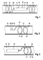
- Fig. 1 shows a schematic representation of a longitudinal section through a cavity formed as an arterial vessel 12 with a preferred embodiment of an implant 10 for local delivery of at least one active ingredient 11 at a predetermined location in the vessel 12.
- the implant 10 comprises a drug reservoir 14, at its two Ends 19 and 20 is connected to two formed as a coil 17 supporting bodies.
- the coil 17 is in each case a helically or spirally wound tube which is arranged in the vessel 12 such that it is arranged coaxially to the vessel 12 and to the drug reservoir 14.
- the coils 17 are self-expanding and thus fix themselves automatically after insertion into the vessel 12 to such an extent that the coils 17 are in contact with the vessel inner wall 13 at their periphery.
- the active substance reservoir 14 is filled with at least one active substance 11, which is introduced by diffusion into the vessel 12 by capillary action.
- the drug outlet 15 is formed by the surface of the drug reservoir 14.
- the active substance reservoir 14 is fixed in the vessel 12 such that the active substance reservoir 14 and thus the active substance outlet 15 are arranged at a distance from the vessel wall 13.
- a load on the vessel wall 13 and / or the lumen is avoided with the active ingredient 11.
- FIG. 2 A further preferred variant according to a further, independent aspect of the invention is shown, wherein the implantable device 10 is designed as a coil 17 which is introduced into an arterial vessel 12.
- the coil 17 serves as a fixing element 21 and at the same time forms the active substance reservoir 14 with an active substance outlet 15.
- the coil 17 has a proximal end 19 and a distal end 20, the proximal end 19 being arranged in the region of the inner wall 13 of the arterial vessel 12. With its distal end 20, the coil 17 is arranged approximately centrally in the cavity 12.
- the distal end 20 forms the active substance outlet 15, which is arranged centrally in the vessel 12.
- FIG. 3 A further variant of an apparatus 10 which can be implanted in an arterial vessel 12 and which comprises a drug reservoir 14 connected to a coil 17 is shown.
- the drug outlet 15 is formed by a porous, in particular perforated shell 16 of the coil 17.
- the active ingredient 11 diffuses via the perforated shell 16 of the coil 17 into the vessel 12, without burdening the wall 13 of the vessel 12 locally with active ingredient 11.
- the drug reservoir 14 may consist of a plurality of drug containers 25a, 25b, 25c, in which each different active ingredients 11a, 11b, 11c are introduced. These can be introduced into the vessel 12, as described in the other figures.
- implantable device 10 is formed from a drug reservoir 14 which is connected at one of its ends 19, 20 with a coil 17.
- the coil 17 is preferably self-expanding and is supported in an end position on the inner wall 13 of the vessel 12 and is thereby fixed.
- the coil 17 serves as a fixing element 21 for the drug reservoir 14, which is particularly preferably held centrally in the vessel 12.
- the drug reservoir 14 is connected to a coil 17 so that it is fixed coaxially to the coil 17 in the vessel 12.
- the drug reservoir 14 is formed as an elongated, cylindrical body, which is connected at its two ends 19, 20 with the coil 17 and coaxially disposed within the coil 17.
- Fig. 7 shows a further variant of a preferred implantable body 10, wherein a drug reservoir 14 at both ends 19, 20 as a stent 18, 18 'formed fixing 21 has.
- the stents 18, 18 ' are expediently self-expanding and fix themselves automatically in a defined end position in the arterial vessel 12.
- the drug reservoir 14 is connected to a stent 18 at a preferably distal end 20.
- the stent 18 serves as a fixing element 21 for the drug reservoir 14, which is held in a central region of the vessel 12.
- a drug reservoir 14 is coaxially fixed by means of a fixing element 21 designed as a stent 18, 18 '.
- the active substance 11 introduced into the active substance reservoir 14 can be released by diffusion into the vessel 12 by capillary action, without impairing the vessel wall 13 or the lumen.
- the active ingredient 11, biodegradable materials forming by the degradation of a shell of the drug reservoir 14, are released into the vessel 12.
- biodegradable materials for example, polymer or metal are used.
- the drug reservoir 14 is formed of a multilayer polymer body 22 of biodegradable materials, wherein spaces between the layers not shown in detail with the at least one active ingredient 11 are filled. After degradation of the layers, the active substance 11 can be released successively into the arterial vessel 12. Alternatively or in addition, a primary diffusion-controlled release of one or more active substances from the biodegradable material can also take place.
- Fig. 10a shows a cross section of the arranged in an arterial vessel 12 polymer body 22, and in Fig. 10b a longitudinal section of the polymer body 22 is shown.
- the polymer body 22 is preferably streamlined and has a proximal end 19 and a distal end 20.
- the active substance-containing polymer body 22 is preferably held in the region of its proximal end 19 by fixing wings 23 in a central position in the vessel 12.
- the fixing wings 23 effect a self-adjustment of the streamlined polymer body 22 in a central region of the arterial vessel 12.
- the fixing wings 23 have a small, preferably linear or point-shaped contact surface 24 on the wall 13 and thus provide a lumen-preserving suspension of the implantable body 10 in FIG If the fixing wings 23 are acted upon by the active substance 11, a small amount of active ingredient enters the wall 13 at most due to the small contact surface 24 to the wall 13. Alternatively, the fixing wings 23 may also be formed drug-free.
Landscapes
- Health & Medical Sciences (AREA)
- Engineering & Computer Science (AREA)
- Life Sciences & Earth Sciences (AREA)
- Biomedical Technology (AREA)
- Public Health (AREA)
- General Health & Medical Sciences (AREA)
- Medicinal Chemistry (AREA)
- Veterinary Medicine (AREA)
- Chemical & Material Sciences (AREA)
- Animal Behavior & Ethology (AREA)
- Heart & Thoracic Surgery (AREA)
- Vascular Medicine (AREA)
- Oral & Maxillofacial Surgery (AREA)
- Epidemiology (AREA)
- Molecular Biology (AREA)
- Transplantation (AREA)
- Dermatology (AREA)
- Bioinformatics & Cheminformatics (AREA)
- Hematology (AREA)
- Cardiology (AREA)
- Anesthesiology (AREA)
- Surgery (AREA)
- Media Introduction/Drainage Providing Device (AREA)
- Materials For Medical Uses (AREA)
- Prostheses (AREA)
- Infusion, Injection, And Reservoir Apparatuses (AREA)
- Medicinal Preparation (AREA)
Abstract
Description
- Die Erfindung betrifft eine implantierbare Vorrichtung nach den Oberbegriffen der unabhängigen Ansprüche.
- In der Medizintechnik sind implantierbare Vorrichtungen zur lokalen Wirkstoffabgabe an vorgegebener Stelle in einen natürlichen Hohlraum eines Säugers, beispielsweise in einen Gewebekanal, vielfach bekannt. Die bestehenden Lösungsvorschläge sind häufig nicht in der Lage, ausreichend große Mengen an Wirkstoff in definierte Regionen einzubringen. Schwierigkeiten ergeben sich oft beim Einsatz von beispielsweise zwei oder mehreren verschiedenen Wirkstoffen zur gleichen Zeit. Andere Lösungsvorschläge betreffen einen voll degradierbaren Gefäßstützkörper mit hoher Wirkstoffbeladung. Problematisch dabei ist, dass derartige Gefäßstützkörper durch direkten Kontakt der Wirkstoff freisetzenden Implantatteile mit der Gefäßwand erhebliche Nebenwirkungen lokal im Gewebe der Gefäßwand hervorrufen können, insbesondere bei der Abgabe von zytostatischen Wirkstoffen. Derartige Nebenwirkungen können aufwendige Therapien zur Prophylaxe und Minderung der Nebenwirkungen zur Folge haben.
- Der Erfindung liegt die Aufgabe zugrunde, eine implantierbare Vorrichtung bereitzustellen, die in der Lage ist, große Mengen eines oder mehrerer Wirkstoffe in einen natürlichen Hohlraum eines Säugers, beispielsweise in einen Gewebekanal, insbesondere in ein arterielles Gefäß, abzugeben, ohne dass dabei die Wand des Hohlraums im Bereich der implantierbaren Vorrichtung mit dem Wirkstoff belastet wird.
- Die Aufgabe wird erfindungsgemäß durch die Merkmale der unabhängigen Ansprüche gelöst. Günstige Ausgestaltungen und Vorteile der Erfindung ergeben sich aus den weiteren Ansprüchen und der Beschreibung.
- Bei einer erfindungsgemäßen implantierbaren Vorrichtung ist wenigstens ein Wirkstoffreservoir vorgesehen, wobei das Wirkstoffreservoir in dem Hohlraum fixierbar ist, und wobei das Wirkstoffreservoir und/oder ein Wirkstoffausgang beabstandet zur Wand so angeordnet ist, dass eine Freisetzung des Wirkstoffs entfernt von der Wand erfolgt. Eine alternative erfindungsgemäße implantierbare Vorrichtung betrifft ein Wirkstoffreservoir mit einem Wirkstoffausgang, wobei der Wirkstoffausgang durch eine perforierte Hülle einer spiralförmig oder schraubenförmig gewundenen Spule gebildet ist. Vorteilhafterweise erlauben diese Lösungsvorschläge eine Implantation von großen Wirkstoffmengen in voraus bestimmte Regionen eines Hohlraums, insbesondere von Arterien, ohne die Gefäßwand mit dem Wirkstoff zu belasten. Günstigerweise können somit unerwünschte Nebenwirkungen wie Entzündungen oder Nekrosen vermieden werden. Nachfolgend wird der Hohlraum nur noch mit Arterie bzw. arteriellem Gefäß bezeichnet.
- Die implantierbare Vorrichtung wird durch ein vorbekanntes Einführsystem (SDS) mittels eines Katheters in das arterielle Gefäß eingebracht. Bevorzugt ist das Implantat als implantierbarer Stützkörper ausgebildet, beispielsweise als Stent, der in das arterielle Gefäß eingebracht wird. In einer Variante kann als implantierbarer Stützkörper auch eine Struktur aus einem schrauben- oder spiralförmigen Röhrchen (Coil) vorgesehen sein, das in das arterielle Gefäß eingesetzt wird. Bevorzugt ist der implantierbare Stützkörper aus Nitinol gebildet. Die implantierbaren Stützkörper können günstigerweise als Fixierelement für ein Wirkstoffreservoir dienen, wobei besonders bevorzugt der Wirkstoffausgang zentral in der Arterie angeordnet ist. Eine ungünstige Belastung der Gefäßwand mit abgegebenen Wirkstoffen kann dabei vermieden werden. Wird mehr als ein Wirkstoff zur Therapie benötigt, kann das Wirkstoffreservoir aus mehreren Wirkstoffbehältern bestehen.
- Das Wirkstoffreservoir kann auch aus mehreren Teilen mit verschiedenen Wirkstoffen bestehen. Das Wirkstoffreservoir weist bevorzugt an wenigstens einem Ende das besonders bevorzugt als Stent und/oder als Spule ausgebildete Fixierelement auf, damit der Wirkstoffausgang in einer definierten Position innerhalb des Gefäßes gehalten und gegen die Hohlraumwände gestützt wird. Das Wirkstoffreservoir kann bevorzugt aus der Spule selbst mit einem proximalen und einem distalen Ende gebildet sein, wobei das proximale Ende an der Innenwand des Gefäßes anliegt. Das proximale Ende der Spule ist dabei günstigerweise so ausgeführt, dass er ohne Beeinflussung der Hämodynamik an der Gefäßwand anliegt. Mit seinem distalen Ende ist die Spule so ausgeführt, dass sie etwa mittig in das arterielle Gefäß ragt, wobei das distale Ende zur Wirkstoffabgabe per Diffusion vorgesehen ist. Je mittiger das distale Ende angeordnet ist, umso vorteilhafter ist es.
- Besonders bevorzugt ist das Wirkstoffreservoir an seinen beiden Enden mit Hilfe der Fixierelemente gehalten, vorzugsweise koaxial fixiert. Günstigerweise wird das Wirkstoffreservoir dabei entweder einseitig oder zweiseitig durch Spulen oder stentartige Stützkörper zentral in der Blutbahn gehaltert. Besonders bevorzugt sind die Spulen und/oder die Stents selbst expandierend und justieren sich somit selbst an einer definierten Stelle in dem Gefäß.
- In einer vorteilhaften Variante kann das Fixierelement selbst den Wirkstoffausgang bilden. Als Wirkstoffreservoir können dabei die Spule oder der Stent selbst dienen, welche besonders bevorzugt eine poröse Hülle aufweisen. Die Wirkstoffabgabe kann dabei per Diffusion über eine kapillare Wirkung erfolgen, wobei wiederum eine lokale Belastung der inneren Gefäßwand durch den abgegebenen Wirkstoff günstigerweise vermieden werden kann. Der Wirkstoff kann dabei vorteilhafterweise mit Hilfe der Kapillarwirkung aus dem Wirkstoffreservoir transportiert und in der Blutbahn freigesetzt werden, ohne dass die Gefäßwand unmittelbar belastet wird.
- In einer weiteren vorteilhaften Variante kann die Wirkstoffabgabe über biologisch abbaubare Materialien erfolgen. Bevorzugt ist das Material aus einem bioabbaubaren Polymer oder aus einem Metall, beispielsweise aus Edelstahl und Tantal, Platin und Nitinol, gebildet. Günstigerweise ist das Wirkstoffreservoir bei dieser Variante aus einem mehrschichtigen Körper aus vorzugsweise biologisch abbaubaren Materialien gebildet, wobei die Räume zwischen den Schichten mit demselben oder mit unterschiedlichen Wirkstoffen ausgefüllt sind. Vorteilhafterweise kann der Wirkstoff nach Abbau der Schichten freigegeben werden, wobei eine ungünstige Belastung der Gefäßwand wiederum entfällt. Sind die Zwischenräume mit demselben Wirkstoff gefüllt, kann die Wirkstoffabgabe günstigerweise gesteuert ablaufen, indem der Wirkstoff über eine ausreichend lange Zeit zur Verfügung gestellt wird. Alternativ oder zusätzlich kann auch eine primär diffusionsgesteuerte Freisetzung eines oder mehrerer Wirkstoffe aus dem biologisch abbaubaren Material erfolgen; als Wirkstoffausgang kann dann die Oberfläche des Körpers dienen.
- In einer weiteren Variante kann das Wirkstoffreservoir aus einem bevorzugt stromlinienförmigen Körper aus einem Polymer gebildet sein, der mit dem gewünschten Wirkstoff beladen ist. Durch die geometrische Form kann der Polymerkörper eine Selbstjustierung des Wirkstoff freisetzenden Implantatteils in der Gefäßmitte bewirken. Der Körper kann weitere Fixierflügel aufweisen, wobei die Fixierflügel kleine Kontaktflächen zur Gefäßwand aufweisen und für eine lumenerhaltende Aufhängung des Implantats im Gefäß sorgen. Die Kontaktfläche ist bevorzugt linienförmig, besonders bevorzugt punktförmig ausgebildet. Vorteilhafterweise ist dabei allenfalls ein geringer Wirkstoffeintrag in die Gefäßwand zu verzeichnen. Alternativ können die Fixierflügel wirkstofffrei ausgeführt sein.
- Die einzelnen Varianten und Ausführungsformen können auch beliebig miteinander kombiniert werden. Bei allen Ausführungsvarianten können vorteilhafterweise große Mengen, beispielsweise 5 mg bis 10 mg, eines oder mehrerer Wirkstoffe in ein arterielles Gefäß abgegeben werden, ohne dass dabei die Gefäßwand im Bereich des Implantats mit dem Wirkstoff belastet wird. Unerwünschte Nebenwirkungen können somit vorteilhafterweise vermieden werden. Bei einer besonders bevorzugten Anwendung kann die erfindungsgemäße implantierbare Vorrichtung in ein arterielles Gefäß kurz vor einem Organ, z.B. der Leber, der Niere etc., eingebracht sein, wobei günstigerweise eine große Menge an Wirkstoff in großem Stromfluss in das Gefäß einbringbar ist, wodurch der Wirkstoff schnell ans Zielgebiet abgegeben wird.
- Die Erfindung ist nachfolgend beispielhaft, anhand von in Zeichnungen dargestellten Ausführungsbeispielen, näher erläutert. Es zeigen in schematischer Darstellung:
- Fig. 1
- einen Schnitt durch einen als arterielles Gefäß ausgebildeten Hohlraum mit einer bevorzugten Ausführungsform einer implantierbaren Vorrich- tung zur lokalen Abgabe wenigstens eines Wirkstoffs an einer vorgege- benen Stelle in das Gefäß, wobei die implantierbare Vorrichtung aus ei- nem Wirkstoffreservoir gebildet ist, das an beiden Enden durch einen jeweils als Spule ausgebildeten Stützkörper fixiert ist;
- Fig. 2
- einen Schnitt durch das arterielle Gefäß mit einer weiteren bevorzugten Variante gemäß einem weiteren, unabhängigen Aspekt der Erfindung
- Fig. 3
- eine Schnittdarstellung durch das arterielle Gefäß mit einer bevorzugten alternativen implantierbaren Vorrichtung, die aus einem Wirkstoffreser- voir und einer Spule mit perforierter Hülle gebildet ist;
- Fig. 4 bis Fig. 9
- weitere Varianten einer implantierbaren Vorrichtung; und
- Fig. 10a, 10b
- eine alternative bevorzugte Ausführungsform einer als im arteriellen Ge- fäß selbstjustierender Polymerkörper ausgebildeten implantierbaren Vor- richtung in einem Querschnitt (
Fig. 10a ) und in einem Längsschnitt (Fig. 10b ). - In den Figuren sind funktionell gleiche oder gleich wirkende Elemente jeweils mit denselben Bezugszeichen beziffert. Die Figuren sind schematische Darstellungen der Erfindung. Sie bilden nicht spezifische Parameter der Erfindung ab. Weiterhin geben die Figuren lediglich typischen Ausgestaltungen der Erfindung wieder und sollen die Erfindung nicht auf die dargestellten Ausgestaltungen beschränken.
-
Fig. 1 zeigt in einer schematischen Darstellung einen Längsschnitt durch einen als arterielles Gefäß 12 ausgebildeten Hohlraum mit einer bevorzugten Ausführungsform eines Implantats 10 zur lokalen Abgabe wenigstens eines Wirkstoffs 11 an einer vorgegebenen Stelle in das Gefäß 12. Das Implantat 10 umfasst ein Wirkstoffreservoir 14, das an seinen beiden Enden 19 und 20 mit zwei als Spule 17 ausgebildeten Stützkörpern verbunden ist. Die Spule 17 ist jeweils ein schrauben- oder spiralförmig gewundenes Röhrchen, das so in dem Gefäß 12 angeordnet ist, dass es koaxial zu dem Gefäß 12 sowie zu dem Wirkstoffreservoir 14 angeordnet ist. Besonders bevorzugt sind die Spulen 17 selbst expandierend und fixieren sich somit selbsttätig nach dem Einbringen in das Gefäß 12 dermaßen, dass die Spulen 17 an ihrer Peripherie mit der Gefäßinnenwand 13 in Kontakt stehen. Das Wirkstoffreservoir 14 ist mit wenigstens einem Wirkstoff 11 befüllt, der per Diffusion durch Kapillarwirkung in das Gefäß 12 eingebracht wird. Der Wirkstoffausgang 15 wird durch die Oberfläche des Wirkstoffreservoirs 14 gebildet. Insbesondere ist das Wirkstoffreservoir 14 so in dem Gefäß 12 fixiert, dass das Wirkstoffreservoir 14 und somit der Wirkstoffausgang 15 beabstandet zur Gefäßwand 13 angeordnet ist. Vorteilhafterweise wird somit eine Belastung der Gefäßwand 13 und/oder des Lumens mit dem Wirkstoff 11 vermieden. - In
Fig. 2 ist eine weitere bevorzugte Variante gemäß einem weiteren, unabhängigen Aspekt der Erfindung gezeigt, wobei die implantierbare Vorrichtung 10 als Spule 17 ausgebildet ist, die in ein arterielles Gefäß 12 eingebracht ist. Die Spule 17 dient als Fixierelement 21 und bildet gleichzeitig das Wirkstoffreservoir 14 mit einem Wirkstoffausgang 15. Die Spule 17 weist ein proximales Ende 19 und ein distales Ende 20 aus, wobei das proximale Ende 19 im Bereich der Innenwand 13 des arteriellen Gefäßes 12 angeordnet ist. Mit ihrem distalen Ende 20 ist die Spule 17 etwa mittig im Hohlraum 12 angeordnet. Das distale Ende 20 bildet den Wirkstoffausgang 15, der zentral im Gefäß 12 angeordnet ist. - In
Fig. 3 ist eine weitere Variante einer in ein arterielles Gefäß 12 implantierbaren Vorrichtung 10 dargestellt, welche ein mit einer Spule 17 verbundenen Wirkstoffreservoir 14 umfasst. Der Wirkstoffausgang 15 ist durch eine poröse, insbesondere perforierte Hülle 16 der Spule 17 gebildet. Der Wirkstoff 11 diffundiert über die perforierte Hülle 16 der Spule 17 in das Gefäß 12, ohne dabei die Wand 13 des Gefäßes 12 lokal mit Wirkstoff 11 zu belasten. - Wie in
Fig. 4 schematisch dargestellt ist, kann das Wirkstoffreservoir 14 aus mehreren Wirkstoffbehältern 25a, 25b, 25c bestehen, in welche jeweils verschiedene Wirkstoffe 11a, 11b, 11c eingebracht sind. Diese können in das Gefäß 12 eingebracht werden, wie in den übrigen Figuren beschrieben ist. - Die in
Fig. 5 dargestellte implantierbare Vorrichtung 10 ist aus einem Wirkstoffreservoir 14 gebildet, das an einem seiner Enden 19, 20 mit einer Spule 17 verbunden ist. Die Spule 17 ist bevorzugt selbst expandierend ausgebildet und stützt sich in einer Endposition an der Innenwand 13 des Gefäßes 12 ab und wird dadurch fixiert. Die Spule 17 dient dabei als Fixierelement 21 für das Wirkstoffreservoir 14, das besonders bevorzugt zentral im Gefäß 12 gehalten wird. - In
Fig. 6 ist das Wirkstoffreservoir 14 so mit einer Spule 17 verbunden, dass es koaxial zur Spule 17 in dem Gefäß 12 fixiert wird. Das Wirkstoffreservoir 14 ist dabei als länglicher, zylindrischer Körper ausgebildet, der an seinen beiden Enden 19, 20 mit der Spule 17 verbunden und koaxial innerhalb der Spule 17 angeordnet ist.Fig. 7 zeigt eine weitere Variante eines bevorzugten implantierbaren Körpers 10, wobei ein Wirkstoffreservoir 14 an beiden Enden 19, 20 ein als Stent 18, 18' ausgebildetes Fixierelement 21 aufweist. Günstigerweise sind die Stents 18, 18' selbst expandierend und fixieren sich selbsttätig in einer definierten Endposition in dem arteriellen Gefäß 12. In einer alternativen Ausführungsform gemäßFig. 8 ist das Wirkstoffreservoir 14 an einem bevorzugt distalen Ende 20 mit einem Stent 18 verbunden. Der Stent 18 dient als Fixierelement 21 für das Wirkstoffreservoir 14, das in einem zentralen Bereich des Gefäßes 12 gehalten wird. In einer weiteren Variante gemäßFig. 9 ist ein Wirkstoffreservoir 14 mit Hilfe eines als Stent 18, 18' ausgebildeten Fixierelements 21 koaxial fixiert. Der in das Wirkstoffreservoir 14 eingebrachte Wirkstoff 11 kann jeweils per Diffusion durch Kapillarwirkung in das Gefäß 12 freigesetzt werden, ohne die Gefäßwand 13 oder das Lumen zu beeinträchtigen. In einer Variante kann der Wirkstoff 11 durch Degradation einer Hülle des Wirkstoffreservoirs 14 bildenden, biologisch abbaubare Materialien, in das Gefäß 12 freigesetzt werden. Als biologisch abbaubare Materialien werden beispielsweise Polymer oder Metall verwendet. - In einer besonders bevorzugten Variante gemäß
Fig. 10a, 10b ist das Wirkstoffreservoir 14 aus einem mehrschichtigen Polymerkörper 22 aus biologisch abbaubaren Materialien gebildet, wobei Räume zwischen den im einzelnen nicht näher dargestellten Schichten mit dem wenigstens einen Wirkstoff 11 gefüllt sind. Nach Abbau der Schichten kann der Wirkstoff 11 sukzessive in das arterielle Gefäß 12 abgegeben werden. Alternativ oder zusätzlich kann auch eine primär diffusionsgesteuerte Freisetzung eines oder mehrerer Wirkstoffe aus dem biologisch abbaubaren Material erfolgen. -
Fig. 10a zeigt einen Querschnitt des in einem arteriellen Gefäß 12 angeordneten Polymerkörpers 22, und inFig. 10b ist ein Längsschnitt des Polymerkörpers 22 gezeigt. Der Polymerkörper 22 ist bevorzugt stromlinienförmig ausgebildet und weist ein proximales Ende 19 und ein distales Ende 20 auf. Der wirkstoffhaltige Polymerkörper 22 ist bevorzugt im Bereich seines proximalen Endes 19 durch Fixierflügel 23 in einer zentralen Position in dem Gefäß 12 gehalten. Die Fixierflügel 23 bewirken eine Selbstjustage des stromlinienförmigen Polymerkörpers 22 in einem zentralen Bereich des arteriellen Gefäßes 12. Die Fixierflügel 23 weisen eine kleine, bevorzugt linienförmig oder punktförmig ausgebildete Kontaktfläche 24 an der Wand 13 auf und sorgen somit für eine lumenerhaltende Aufhängung des implantierbaren Körpers 10 im Gefäß 12. Sind die Fixierflügel 23 mit Wirkstoff 11 beaufschlagt, findet aufgrund der kleinen Kontaktfläche 24 zur Wand 13 allenfalls ein geringer Wirkstoffeintrag in die Wand 13 statt. Alternativ können die Fixierflügel 23 auch wirkstofffrei ausgebildet sein.
Claims (15)
- Implantierbare Vorrichtung zur lokalen Abgabe wenigstens eines Wirkstoffs (11) an vorgegebener Stelle in einen natürlichen Hohlraum (12) mit einer Wand (13) im Körper eines Säugers, gekennzeichnet durch wenigstens ein Wirkstoffreservoir (14), das in dem Hohlraum (12) fixierbar ist, wobei das Wirkstoffreservoir (14) und/oder ein Wirkstoffausgang (15) beabstandet zur Wand (13) so angeordnet ist, dass eine Freisetzung des wenigstens einen Wirkstoffs (11) entfernt zur Wand (13) erfolgt.
- Implantierbare Vorrichtung zur lokalen Abgabe wenigstens eines Wirkstoffs (11) an vorgegebener Stelle in einen natürlichen Hohlraum (12) mit einer Wand (13) im Körper eines Säugers, gekennzeichnet durch wenigstens ein Wirkstoffreservoir (14) mit einem Wirkstoffausgang (15), wobei der Wirkstoffausgang (15) durch eine perforierte Hülle (16) einer spiralförmig oder schraubenförmig gewundenen Spule (17) gebildet ist.
- Implantierbare Vorrichtung nach Anspruch 1 oder 2, dadurch gekennzeichnet, dass der Wirkstoffausgang (15) zentral im Hohlraum (12) angeordnet ist.
- Implantierbare Vorrichtung nach wenigstens einem der vorhergehenden Ansprüche, dadurch gekennzeichnet, dass das wenigstens eine Wirkstoffreservoir (14) an wenigstens einem Ende (19, 20) ein Fixierelement (21) aufweist, das gegen die Hohlraumwände (13) gestützt ist.
- Implantierbare Vorrichtung Anspruch 4, dadurch gekennzeichnet, dass das Fixierelement (21) den Wirkstoffausgang (15) bildet.
- Implantierbare Vorrichtung nach einem der vorhergehenden Ansprüche 4 oder 5, dadurch gekennzeichnet, dass als Wirkstoffreservoir (14) das Fixierelement (21) ausgebildet ist.
- Implantierbare Vorrichtung nach einem der vorhergehenden Ansprüche, dadurch gekennzeichnet, dass das Wirkstoffreservoir (14) aus mehreren Wirkstoffbehältern (25a, 25b, 25c) besteht.
- Implantierbare Vorrichtung nach einem der vorhergehenden Ansprüche, dadurch gekennzeichnet, dass als Wirkstoffreservoir (14) die Spule (17) oder ein implantierbarer Stützkörper (Stent) (18) vorgesehen ist.
- Implantierbare Vorrichtung nach einem der vorhergehenden Ansprüche, dadurch gekennzeichnet, dass das Wirkstoffreservoir (14) mit Hilfe des Fixierelements (21) koaxial fixiert ist.
- Implantierbare Vorrichtung nach einem der vorhergehenden Ansprüche, dadurch gekennzeichnet, dass das Wirkstoffreservoir (14) aus der Spule (17) mit einem proximalen Ende (19) und einem distalen Ende (20) gebildet ist, wobei das proximale Ende (19) an der Innenwand (13) des Hohlraums (12) anliegt und die Spule (17) mit ihrem distalen Ende (20) etwa mittig im Hohlraum (12) angeordnet ist, und wobei das distale Ende (20) zur Abgabe des Wirkstoffs (11) vorgesehen ist.
- Implantierbare Vorrichtung nach einem der vorhergehenden Ansprüche, dadurch gekennzeichnet, dass der wenigstens eine Wirkstoff (11) im Wirkstoffreservoir (14) durch Diffusion über Kapillarwirkung in den Hohlraum (12) freisetzbar ist.
- Implantierbare Vorrichtung nach einem der vorhergehenden Ansprüche, dadurch gekennzeichnet, dass der wenigstens eine Wirkstoff (11) durch biologisch abbaubare Materialien in den Hohlraum (12) freisetzbar ist.
- Implantierbare Vorrichtung nach einem der vorhergehenden Ansprüche, dadurch gekennzeichnet, dass das Wirkstoffreservoir (14) aus einem mehrschichtigen Körper aus vorzugsweise biologisch abbaubaren Materialien gebildet ist, wobei Räume zwischen den Schichten mit dem wenigstens einen Wirkstoff (11) gefüllt sind, und der Wirkstoff (11) nach Abbau der Schichten sukzessive in den Hohlraum (12) abgebbar ist.
- Vorrichtung nach einem der vorhergehenden Ansprüche, dadurch gekennzeichnet, dass ein Polymerkörper (22) vorgesehen ist, der durch seine geometrische Form eine Selbstjustage des Wirkstoffreservoirs (14) in der Mitte des Hohlraums (12) bewirkt.
- Vorrichtung nach Anspruch 14, dadurch gekennzeichnet, dass der Polymerkörper (22) wenigstens zwei Fixierflügel (23) aufweist, die eine kleine Kontaktfläche (24) zur Wand (13) des Hohlraums (12) aufweisen.
Applications Claiming Priority (1)
| Application Number | Priority Date | Filing Date | Title |
|---|---|---|---|
| DE102008002397A DE102008002397A1 (de) | 2008-06-12 | 2008-06-12 | Implantierbare Vorrichtung |
Publications (2)
| Publication Number | Publication Date |
|---|---|
| EP2133045A2 true EP2133045A2 (de) | 2009-12-16 |
| EP2133045A3 EP2133045A3 (de) | 2010-07-21 |
Family
ID=40940623
Family Applications (1)
| Application Number | Title | Priority Date | Filing Date |
|---|---|---|---|
| EP09160150A Withdrawn EP2133045A3 (de) | 2008-06-12 | 2009-05-13 | Implantierbare Vorrichtung |
Country Status (3)
| Country | Link |
|---|---|
| US (1) | US8062352B2 (de) |
| EP (1) | EP2133045A3 (de) |
| DE (1) | DE102008002397A1 (de) |
Families Citing this family (16)
| Publication number | Priority date | Publication date | Assignee | Title |
|---|---|---|---|---|
| CA2750478C (en) * | 2009-01-23 | 2015-04-07 | Endoluminal Sciences Pty Ltd. | Endovascular devices and associated systems and methods |
| US9283305B2 (en) | 2009-07-09 | 2016-03-15 | Medtronic Vascular, Inc. | Hollow tubular drug eluting medical devices |
| US8678046B2 (en) | 2009-09-20 | 2014-03-25 | Medtronic Vascular, Inc. | Apparatus and methods for loading a drug eluting medical device |
| US8828474B2 (en) | 2009-09-20 | 2014-09-09 | Medtronic Vascular, Inc. | Apparatus and methods for loading a drug eluting medical device |
| US20110070358A1 (en) | 2009-09-20 | 2011-03-24 | Medtronic Vascular, Inc. | Method of forming hollow tubular drug eluting medical devices |
| US8381774B2 (en) | 2009-09-20 | 2013-02-26 | Medtronic Vascular, Inc. | Methods for loading a drug eluting medical device |
| WO2011139594A2 (en) * | 2010-04-27 | 2011-11-10 | Medtronic, Inc. | Artificial bursa for intra-articular drug delivery |
| DK2600800T3 (da) * | 2010-08-05 | 2020-11-16 | Taris Biomedical Llc | Indretning til lægemiddellevering i en ureterstent og kit dertil |
| US8333801B2 (en) | 2010-09-17 | 2012-12-18 | Medtronic Vascular, Inc. | Method of Forming a Drug-Eluting Medical Device |
| US8616040B2 (en) | 2010-09-17 | 2013-12-31 | Medtronic Vascular, Inc. | Method of forming a drug-eluting medical device |
| US8632846B2 (en) | 2010-09-17 | 2014-01-21 | Medtronic Vascular, Inc. | Apparatus and methods for loading a drug eluting medical device |
| US9744341B2 (en) * | 2013-01-15 | 2017-08-29 | Palo Alto Research Center Incorporated | Devices and methods for intraluminal retention and drug delivery |
| EP2967938B1 (de) | 2013-03-14 | 2017-03-01 | Medtronic Vascular Inc. | Verfahren zur herstellung eines stents und dadurch hergestellter stent |
| US10010400B2 (en) | 2015-03-30 | 2018-07-03 | Taris Biomedical Llc | Devices and methods for local delivery of drug to upper urinary tract |
| CN116407748A (zh) * | 2021-12-31 | 2023-07-11 | 先健科技(深圳)有限公司 | 放疗支架和回收系统 |
| EP4568616A2 (de) * | 2022-08-09 | 2025-06-18 | The General Hospital Corporation | Endovaskulärer biologischer stent |
Family Cites Families (17)
| Publication number | Priority date | Publication date | Assignee | Title |
|---|---|---|---|---|
| US5002772A (en) * | 1988-05-31 | 1991-03-26 | Pfizer Inc. | Gastric retention system for controlled drug release |
| US5500013A (en) * | 1991-10-04 | 1996-03-19 | Scimed Life Systems, Inc. | Biodegradable drug delivery vascular stent |
| US5704910A (en) * | 1995-06-05 | 1998-01-06 | Nephros Therapeutics, Inc. | Implantable device and use therefor |
| US5603694A (en) * | 1995-10-17 | 1997-02-18 | Brown; Joe E. | Infusion coil apparatus and method for delivering fluid-based agents intravascularly |
| ZA9710342B (en) * | 1996-11-25 | 1998-06-10 | Alza Corp | Directional drug delivery stent and method of use. |
| US7208010B2 (en) * | 2000-10-16 | 2007-04-24 | Conor Medsystems, Inc. | Expandable medical device for delivery of beneficial agent |
| US6358276B1 (en) * | 1998-09-30 | 2002-03-19 | Impra, Inc. | Fluid containing endoluminal stent |
| US7651696B2 (en) * | 2000-08-25 | 2010-01-26 | Nexeon Medical Systems, Inc. | Implantable device for treating disease states and methods of using same |
| IL143007A0 (en) * | 2001-05-07 | 2002-04-21 | Rafael Medical Technologies In | Retrievable intravascular support structures |
| IN2014DN10834A (de) * | 2001-09-17 | 2015-09-04 | Psivida Inc | |
| US20040133270A1 (en) * | 2002-07-08 | 2004-07-08 | Axel Grandt | Drug eluting stent and methods of manufacture |
| NL1021892C2 (nl) | 2002-11-11 | 2004-05-12 | Tno | Detectie van demyelinisatie. |
| US7226473B2 (en) * | 2003-05-23 | 2007-06-05 | Brar Balbir S | Treatment of stenotic regions |
| GB0402736D0 (en) | 2004-02-06 | 2004-03-10 | Tayside Flow Technologies Ltd | A drug delivery device |
| US7811316B2 (en) * | 2006-05-25 | 2010-10-12 | Deep Vein Medical, Inc. | Device for regulating blood flow |
| US20100016957A1 (en) * | 2006-05-26 | 2010-01-21 | Edwin Jager | Device and method for controlled delivery of chemical substances |
| DE102006038232A1 (de) | 2006-08-07 | 2008-02-14 | Biotronik Vi Patent Ag | Endoprothese und Verfahren zur Herstellung einer solchen |
-
2008
- 2008-06-12 DE DE102008002397A patent/DE102008002397A1/de not_active Withdrawn
-
2009
- 2009-05-13 EP EP09160150A patent/EP2133045A3/de not_active Withdrawn
- 2009-06-09 US US12/481,218 patent/US8062352B2/en not_active Expired - Fee Related
Also Published As
| Publication number | Publication date |
|---|---|
| US8062352B2 (en) | 2011-11-22 |
| DE102008002397A1 (de) | 2009-12-17 |
| EP2133045A3 (de) | 2010-07-21 |
| US20090312833A1 (en) | 2009-12-17 |
Similar Documents
| Publication | Publication Date | Title |
|---|---|---|
| EP2133045A2 (de) | Implantierbare Vorrichtung | |
| DE69222305T2 (de) | Erweiterungssystem für hohle körperleitungen | |
| DE69825162T2 (de) | Intravaskulärer stent mit einer ablenkvorrichtung | |
| DE60217878T2 (de) | Expandierbare medizinische Vorrichtung zur Abgabe eines Heilmittels | |
| EP2214768B1 (de) | Katheter | |
| DE69736369T2 (de) | Selbstexpandierbarer Stent aus einer Titanlegierung | |
| DE69610641T2 (de) | Vaso-okklusive Spiralfeder mit wechselnder Steifheit | |
| DE69630030T2 (de) | Endovaskularer stent | |
| EP2811937B1 (de) | Stentgraft mit fixierelementen und einführsystem | |
| DE69926644T2 (de) | Medikamentenzufuhrsysteme | |
| DE602004010344T2 (de) | Katheter ohne Ballon zum Einsetzen eines Stents | |
| DE102004029611A1 (de) | Implantat zur Freisetzung eines Wirkstoffs in ein von einem Körpermedium durchströmtes Gefäß | |
| EP3322387B1 (de) | Ballonkatheter | |
| EP0578998A1 (de) | In der Körper eines Patienten perkutan implantierbare Endoprothese | |
| EP3463206B1 (de) | Vasospasmusbehandlung | |
| EP1419793A1 (de) | Endoprothese mit einer Trägerstruktur aus einer Magnesiumlegierung | |
| DE102006056283A1 (de) | Okklusionsvorrichtung und Einführvorrichtung für diese sowie System aus Okklusionsvorrichtung und Einführvorrichtung | |
| DE29624503U1 (de) | Arzneimittel-freisetzender beschichteter Stent | |
| WO2009077845A2 (de) | Stützimplantat, insbesondere stent, und implantationskatheter für das stützimplantat | |
| DE102009009003A1 (de) | Implantat | |
| DE112024000033T5 (de) | Medikamententragender Einkerbungsballon und Ballonkatheter | |
| DE10317241A1 (de) | Stent | |
| DE102007060497A1 (de) | Implantierbare Gefäßstütze | |
| DE10333511A1 (de) | Stentimplantationssystem sowie Gefässstütze | |
| EP1878464B1 (de) | Implantierbare Elektrodenvorrichtung |
Legal Events
| Date | Code | Title | Description |
|---|---|---|---|
| PUAI | Public reference made under article 153(3) epc to a published international application that has entered the european phase |
Free format text: ORIGINAL CODE: 0009012 |
|
| AK | Designated contracting states |
Kind code of ref document: A2 Designated state(s): AT BE BG CH CY CZ DE DK EE ES FI FR GB GR HR HU IE IS IT LI LT LU LV MC MK MT NL NO PL PT RO SE SI SK TR |
|
| PUAL | Search report despatched |
Free format text: ORIGINAL CODE: 0009013 |
|
| AK | Designated contracting states |
Kind code of ref document: A3 Designated state(s): AT BE BG CH CY CZ DE DK EE ES FI FR GB GR HR HU IE IS IT LI LT LU LV MC MK MT NL NO PL PT RO SE SI SK TR |
|
| AX | Request for extension of the european patent |
Extension state: AL BA RS |
|
| RIC1 | Information provided on ipc code assigned before grant |
Ipc: A61F 2/86 20060101ALI20100615BHEP Ipc: A61L 31/16 20060101ALI20100615BHEP Ipc: A61M 31/00 20060101AFI20100615BHEP |
|
| STAA | Information on the status of an ep patent application or granted ep patent |
Free format text: STATUS: THE APPLICATION IS DEEMED TO BE WITHDRAWN |
|
| 18D | Application deemed to be withdrawn |
Effective date: 20110122 |