EP2133247A2 - Agencement de soupape de freinage de stationnement - Google Patents
Agencement de soupape de freinage de stationnement Download PDFInfo
- Publication number
- EP2133247A2 EP2133247A2 EP09007417A EP09007417A EP2133247A2 EP 2133247 A2 EP2133247 A2 EP 2133247A2 EP 09007417 A EP09007417 A EP 09007417A EP 09007417 A EP09007417 A EP 09007417A EP 2133247 A2 EP2133247 A2 EP 2133247A2
- Authority
- EP
- European Patent Office
- Prior art keywords
- parking brake
- valve
- arrangement according
- trailer
- control line
- Prior art date
- Legal status (The legal status is an assumption and is not a legal conclusion. Google has not performed a legal analysis and makes no representation as to the accuracy of the status listed.)
- Granted
Links
Images



Classifications
-
- B—PERFORMING OPERATIONS; TRANSPORTING
- B60—VEHICLES IN GENERAL
- B60T—VEHICLE BRAKE CONTROL SYSTEMS OR PARTS THEREOF; BRAKE CONTROL SYSTEMS OR PARTS THEREOF, IN GENERAL; ARRANGEMENT OF BRAKING ELEMENTS ON VEHICLES IN GENERAL; PORTABLE DEVICES FOR PREVENTING UNWANTED MOVEMENT OF VEHICLES; VEHICLE MODIFICATIONS TO FACILITATE COOLING OF BRAKES
- B60T13/00—Transmitting braking action from initiating means to ultimate brake actuator with power assistance or drive; Brake systems incorporating such transmitting means, e.g. air-pressure brake systems
- B60T13/10—Transmitting braking action from initiating means to ultimate brake actuator with power assistance or drive; Brake systems incorporating such transmitting means, e.g. air-pressure brake systems with fluid assistance, drive, or release
- B60T13/24—Transmitting braking action from initiating means to ultimate brake actuator with power assistance or drive; Brake systems incorporating such transmitting means, e.g. air-pressure brake systems with fluid assistance, drive, or release the fluid being gaseous
- B60T13/26—Compressed-air systems
- B60T13/261—Compressed-air systems systems with both indirect application and application by springs or weights and released by compressed air
- B60T13/263—Compressed-air systems systems with both indirect application and application by springs or weights and released by compressed air specially adapted for coupling with dependent systems, e.g. tractor-trailer systems
-
- B—PERFORMING OPERATIONS; TRANSPORTING
- B60—VEHICLES IN GENERAL
- B60T—VEHICLE BRAKE CONTROL SYSTEMS OR PARTS THEREOF; BRAKE CONTROL SYSTEMS OR PARTS THEREOF, IN GENERAL; ARRANGEMENT OF BRAKING ELEMENTS ON VEHICLES IN GENERAL; PORTABLE DEVICES FOR PREVENTING UNWANTED MOVEMENT OF VEHICLES; VEHICLE MODIFICATIONS TO FACILITATE COOLING OF BRAKES
- B60T13/00—Transmitting braking action from initiating means to ultimate brake actuator with power assistance or drive; Brake systems incorporating such transmitting means, e.g. air-pressure brake systems
- B60T13/10—Transmitting braking action from initiating means to ultimate brake actuator with power assistance or drive; Brake systems incorporating such transmitting means, e.g. air-pressure brake systems with fluid assistance, drive, or release
- B60T13/24—Transmitting braking action from initiating means to ultimate brake actuator with power assistance or drive; Brake systems incorporating such transmitting means, e.g. air-pressure brake systems with fluid assistance, drive, or release the fluid being gaseous
- B60T13/26—Compressed-air systems
- B60T13/38—Brakes applied by springs or weights and released by compressed air
- B60T13/385—Control arrangements therefor
-
- B—PERFORMING OPERATIONS; TRANSPORTING
- B60—VEHICLES IN GENERAL
- B60T—VEHICLE BRAKE CONTROL SYSTEMS OR PARTS THEREOF; BRAKE CONTROL SYSTEMS OR PARTS THEREOF, IN GENERAL; ARRANGEMENT OF BRAKING ELEMENTS ON VEHICLES IN GENERAL; PORTABLE DEVICES FOR PREVENTING UNWANTED MOVEMENT OF VEHICLES; VEHICLE MODIFICATIONS TO FACILITATE COOLING OF BRAKES
- B60T13/00—Transmitting braking action from initiating means to ultimate brake actuator with power assistance or drive; Brake systems incorporating such transmitting means, e.g. air-pressure brake systems
- B60T13/10—Transmitting braking action from initiating means to ultimate brake actuator with power assistance or drive; Brake systems incorporating such transmitting means, e.g. air-pressure brake systems with fluid assistance, drive, or release
- B60T13/66—Electrical control in fluid-pressure brake systems
- B60T13/665—Electrical control in fluid-pressure brake systems the systems being specially adapted for transferring two or more command signals, e.g. railway systems
- B60T13/667—Electrical control in fluid-pressure brake systems the systems being specially adapted for transferring two or more command signals, e.g. railway systems and combined with electro-magnetic brakes
Definitions
- the invention relates to an electrically controlled parking brake valve assembly for a braking system of a commercial vehicle, wherein the parking brake valve assembly comprises two ports, one port of which is provided to pressurize a trailer control valve assembly so that the trailer in the park braking operation of the commercial vehicle mitbremst, while the other connection to it is provided to pressurize the trailer control valve assembly so that the trailer does not brake in the parking brake operation of the commercial vehicle.
- Parking brake systems comprise a service brake system and a parking brake system, which are usually controlled independently of one another pneumatically or electropneumatically.
- Parking brake systems usually comprise spring-loaded cylinders which, in their vented state, brake the vehicle while the parking brake can be released by aerating the spring-loaded cylinders.
- the parking brakes of a trailer connected to a utility vehicle are actuated via a trailer control valve assembly which can be pneumatically connected to a parking brake valve assembly of the utility vehicle.
- a trailer control valve assembly which can be pneumatically connected to a parking brake valve assembly of the utility vehicle.
- the invention is therefore the object of developing an electrically controlled parking brake valve assembly such that the modes “trailer brakes in parking position with” and “trailer brakes not in parking position with” in an electropneumatic circuit in a cost effective and less prone to failure manner be realized.
- the electrically controlled parking brake valve assembly comprises at most two solenoid valves, in particular a first solenoid valve and a second solenoid valve.
- the parking brake valve assembly is limited to a minimum of costly and subject to mechanical wear subject switching elements. Since each electrically switched valve also represents an additional power consumers, so the energy consumption and ultimately the fuel consumption of the commercial vehicle is lowered.
- a pneumatic piping in the cab of the utility vehicle to operate the parking brake valve assembly is not needed because it is an electrically controlled system.
- the Parkbremsventilanordung remains in the last set operating condition. This ensures that in the absence of signals to control the solenoid valves, for example in the event of a power failure, no safety-critical operating state of the vehicle is caused. Instead, the just current pressure conditions at the connections to the trailer control valve arrangement and the control input of the relay valve, which regulates the pressure on the spring-loaded parking brake of the utility vehicle, are maintained. For example, even if the power supply fails, the parking brake of the towing vehicle or the trailer will not lock when a driving condition exists. Accordingly, the parking brakes are not released when no power supply is available. That is, a vehicle in which the power supply is not guaranteed by an error, can not drive away.
- a control input of the relay valve is connected to an output of the first solenoid valve and an input of the first solenoid valve is connected via a first control line to the second terminal and an output of the second solenoid valve, via which the first control line is pressurized can be.
- the first control line can be vented via the second solenoid valve.
- the second solenoid valve can be controlled with a single solenoid valve, whether the control line is supplied with compressed air or vented.
- a preferred embodiment of a parking brake valve arrangement provides that the control input of the relay valve is connected to the first connection via a first check valve and a second control line.
- the control input of the relay valve is connected to the first connection via a first check valve and a second control line.
- the control input of the relay valve is subjected to a pressure, so that this puts the spring-loaded parking brake of the commercial vehicle in a driving state, and the first port to the trailer control valve assembly is pressurized, so that also a trailer associated with it is put into a driving state.
- Due to the first check valve but now venting the second control line is decoupled from venting the control input of the relay valve, so that the commercial vehicle can be braked without having to slow down a trailer connected to the first port, which is braked in parking position.
- the embodiment is further developed in that the second control line is connected via a second check valve to the first control line.
- the second control line can be vented via the second check valve.
- the second control line does not have to be vented.
- the first solenoid valve is a bistable 3/2-way valve.
- bistable valves retain their switching state even when the control signal is lost and are only switched to another state by another control signal.
- the first solenoid valve in case of failure of the power supply in a driving mode in which the first solenoid valve does not connect the control loop of the relay valve with the vent, so that the driving mode is maintained. In a parking operating state, it is thus possible to prevent the parking brake of the utility vehicle from being released without active activation of the first solenoid valve.
- a second solenoid valve is a monostable 3/2-way valve. This makes it possible to connect the first control line to the second port and to a first solenoid valve either with the compressed air source or with the vent.
- a first solenoid valve either with the compressed air source or with the vent.
- the first control line to the compressed air source can ensuring that a trailer connected to the second port is not braked.
- connections and a connection to the parking brake of the utility vehicle can be subjected to gradual pressure.
- a stepwise stepped / increased or graduated / reduced pressure is set. If this stepwise pressure regulation is implemented by switching the second solenoid valve, the height and the gradient of the pressure at the connections can be influenced by the ratio of the valve being switched off.
- a parking brake valve arrangement comprising a pressure sensor and an electronic control unit, wherein the electronic control unit receives signals from the pressure sensor and outputs electrical signals for actuating the solenoid valves.
- the electronic control unit can process the measurement signal and process the information about the operating state of the parking brake. These can, for example via a communication network of the vehicle, for example a CAN, with which the electronic control unit can communicate with other control devices in the vehicle, be forwarded to a dashboard in the cab.
- the electronic control unit is used to control the solenoid valves.
- the measurement signal of the pressure measurement at the output of the relay valve is used to measure the stepped pressure in a state of gradual braking. This is processed by the electronic control unit and used to control the second solenoid valve.
- a preferred embodiment of the invention provides that it is integrated in an electronic air treatment unit. This allows a cost-effective Implementation of electronic control components and energy-saving operation of the pneumatic system.
- a parking brake valve arrangement designed to automatically determine the functionality of the parking brake of the utility vehicle during each parking operation.
- a driver of a commercial vehicle must be able to ascertain at all times that the effect of the parking brake, ie the parking brake, of the vehicle combination achieved solely by the mechanical parking brake system is sufficient.
- the parking brake valve arrangement according to the invention it is checked whether the parking brake of the towing vehicle can hold the combination of towing vehicle and trailer and the driver immediately receives a message about the test result.
- the invention provides that the last observed operability of the parking brake can be output at any time.
- the driver will not only be informed of the result automatically at or immediately after a trailer test has been carried out, but will also be able to inform himself at any time about the result of the last test performed.
- a "trailer test" button can be provided, with which the driver can request the information.
- the last proven functionality of the parking brake is output via an optical or acoustic signal.
- the driver may be provided with information that may be critical to safety in a manner that can be detected quickly.
- the process of determining the operability of the parking brake can be canceled at any time.
- a rolling vehicle is detected, be reacted immediately to end this safety-critical state. After an abort due to insufficient braking effect of the parking brake of the commercial vehicle brakes the trailer, so that in this way immediately a safe operating condition can be restored.
- a solid pneumatic connecting line symbolizes a pressurized pneumatic connection, a dashed line with longer lines a non-elevated pressure connection, a dotted line a compound in which due to a permanent change between ventilation and the pressure conditions gradable change.
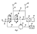
- FIG. 1 12 shows a schematic representation of a utility vehicle 44 having a braking system 46 that includes a parking brake valve assembly 10 according to the present invention integrated with an electronic air conditioning unit 54 having a pneumatic connection 36 to the parking brakes 24 of the utility vehicle and two ports 40, 42 to a trailer control valve assembly 48 which is connected to the parking brakes 50 of a trailer 52, wherein one terminal 42 is provided for use when the trailer 52 is not to be braked when the parking brake 24 of the utility vehicle 44 is engaged, and the other terminal 40 is used, if the trailer 52 is to be braked when the parking brake 24 of the utility vehicle 44 is engaged.
- the respectively not required connection is closed.
- FIG. 2 shows a schematic representation of an embodiment of a parking brake valve assembly 10 according to the invention, which uses a bistable first 3/2-way solenoid valve 14 for controlling a parking brake relay valve 16, with which the first pneumatic connection 36 to the commercial vehicle parking brakes 24 applied with a pressure can be.
- the control input of the relay valve 16 is connected via a third control line 34 to the output of the bistable first 3/2-way solenoid valve 14.
- the first pneumatic connection 36 is supplied with compressed air via the second pneumatic connection 38, so that the parking brake 24 is released.
- the first control line 32 is also connected to a second check valve 22, via which the second control line 30 can be vented at vented first control line 32. Via the first check valve 20, the second control line 30 and thus the first port 40 can be supplied with compressed air via the third control line 34.
- a pressure sensor 26 is provided which measures the pressure in the first pneumatic connection 36 and forwards the measured values to an electronic control unit 28. This processes the measurement signal and thus obtains information about the operating state of the parking brake 24.
- the electronic control unit 28 controls the switching states of the solenoid valves 12, 14, whereby various operating states of the parking brake valve assembly 10 are realized, which are based on the FIGS. 3 to 7 are explained and summarized in Table 1: Table 1, switching states of the solenoid valves 12, 14th operating condition Solenoid valves 12 Solenoid valve 14 Drive 0 0 Parking 1 1-> 0 1 Parking 2 0 1 Trailer Test 0 1 Gradual pressure change 1..0 0
- FIG. 3 shows a parking brake valve assembly accordingly FIG. 2 , which is in a "driving" operating state.
- the monostable second solenoid valve 12 and the input of the parking brake relay valve 16 is pressurized.
- the de-energized switching state "0" thereby the first control line 32 and thus the second port 42 is pressurized.
- the second check valve 22 prevents compressed air from the first control line 32 on this way to the second control line 30 passes.
- the bistable first solenoid valve 14 is in the switching state "0" in which it passes the pressure in the third control line 34 and thus to the control input of the relay valve 16 and the first check valve 20.
- a pressure sensor 26 measures the pressure in the first pneumatic connection 36 at the output of the relay valve 16. This information is processed by the electronic control unit 28 and forwarded via a CAN network of the vehicle to the dashboard in the cab. A sufficiently high measured pressure also means that the parking brake is released.
- fail-safe behavior ie the behavior of the arrangement in case of failure of the power supply is in the operating state "driving" in that the driving state is maintained, since the two solenoid valves 12, 14 each remain in the current state "0" in the current state.
- FIG. 4 shows a parking brake valve assembly accordingly FIG. 2 , which is in a "Traiter Test” mode. This remains in this state second solenoid valve 12 in the switching state "0" and forwards the pressure to the second port 42.
- the first solenoid valve 14 is switched to the switching position "1", so that the third control line 34 is no longer connected to the first control line 32, so that the third control line 34 is vented via the first solenoid valve 14 and no control pressure is applied to the control input of the relay valve 16.
- the relay valve 16 output and vent are connected to each other, the spring accumulator 24 vented and the vehicle braked.
- the vehicle movement can now be detected, for example, via the vehicle speed or wheel speed sensors and read in and evaluated via a suitable control electronics 28.
- the driver can then be notified via a display panel or an acoustic warning signal can be issued if the condition is unstable.
- the driver is still a test button available, with which he can always reissue the last found test result.
- the FailSafe behavior in the operating state trailer test in case of failure of the power supply is given by the fact that the vehicle, if the first solenoid valve 14 has already completed its switching operation, reaches the desired braked final state. If the shift is not completed, the vehicle remains in the unrestrained driving state.
- FIG. 5 and FIG. 6 show a parking brake valve assembly accordingly FIG. 2 , which is first in a first, then in a second operating state "Parking".
- the second solenoid valve 12 is switched to the switching state "1" and the first control line 32 is not supplied with compressed air, but is vented via the second solenoid valve 12.
- the second port 42 is no longer pressurized.
- the pressure now also builds up at the first port 40.
- the control input of the relay valve 16 is vented, so that the spring-loaded parking brakes 24 are vented and the vehicle can not be moved.
- the sensor 26 does not measure pressure in this state.
- This information is processed by the electronic control unit 28 and forwarded, for example via a CAN network of the vehicle to the dashboard in the cab. If no pressure is measured, this means that the parking brake 24 is engaged. Then, the second solenoid valve 12 is again placed in the de-energized switching state "0", in which it directs compressed air into the first control line 32 and thus to the second port 42.
- FIG. 6 is the thus adjusting second Park sesshunt shown.
- the second check valve 22 shuts off the second control line 30 and thus the first connection 40 against the first control line 32, so that a trailer 52 connected to the first connection 40 is braked, a trailer 52 connected to the second connection 42 is not.
- FailSafe behavior in the event of power failure during the parking operation, if the shift of the second solenoid valve 12 does not complete, the vehicle remains in the condition as after the trailer test function. When the switching process is completed, the desired final state is reached. So there can be no safety-critical situation.
- FIG. 7 shows a parking brake valve assembly accordingly FIG. 2 , which is in an operating state "gradable braking", ie a gradable pressure change, is.
- the second solenoid valve 12 is set by permanent switching on and off and thus the permanent switching on and off of compressed air supply 56 and venting in a state that sets a graded / reduced pressure in the first control line 32, wherein the height of the pressure about the ratio of on-off state of the valve 12th can be influenced.
- This pressure is also set at the second port 42 and at the entrance of the first solenoid valve 14.
- the pressure at the control input of the relay valve 16 is gradually reduced and thus the pressure on the spring-loaded parking brakes 24 of the utility vehicle 44 via the second check valve 22 is also in the second control line 30th and thus reduced at the first port 40 of the pressure step. Since the pressure is reduced at both terminals 40, 42, a trailer 52, which is connected to one of the terminals, braked stepped. If the pressure at the input of the parking brake relay valve 16 is to be increased, this is achieved by changing the ratio of the time proportions for the switching states of the second solenoid valve 12.
- the FailSafe behavior in case of failure of the power supply is given in the operating state "gradual braking” characterized in that the second solenoid valve 12 falls to its idle state "0", so that the vehicle remains in the driving state.
Landscapes
- Engineering & Computer Science (AREA)
- Transportation (AREA)
- Mechanical Engineering (AREA)
- Valves And Accessory Devices For Braking Systems (AREA)
- Braking Systems And Boosters (AREA)
- Regulating Braking Force (AREA)
Applications Claiming Priority (1)
| Application Number | Priority Date | Filing Date | Title |
|---|---|---|---|
| DE200810027732 DE102008027732B3 (de) | 2008-06-11 | 2008-06-11 | Parkbremsventilanordnung |
Publications (3)
| Publication Number | Publication Date |
|---|---|
| EP2133247A2 true EP2133247A2 (fr) | 2009-12-16 |
| EP2133247A3 EP2133247A3 (fr) | 2011-09-21 |
| EP2133247B1 EP2133247B1 (fr) | 2012-10-10 |
Family
ID=41119633
Family Applications (1)
| Application Number | Title | Priority Date | Filing Date |
|---|---|---|---|
| EP20090007417 Active EP2133247B1 (fr) | 2008-06-11 | 2009-06-04 | Agencement de soupape de freinage de stationnement |
Country Status (2)
| Country | Link |
|---|---|
| EP (1) | EP2133247B1 (fr) |
| DE (1) | DE102008027732B3 (fr) |
Cited By (10)
| Publication number | Priority date | Publication date | Assignee | Title |
|---|---|---|---|---|
| CN106515696A (zh) * | 2016-12-23 | 2017-03-22 | 南京理工大学 | 用于中重型车辆的气压可调式电子制动系统 |
| CN107672575A (zh) * | 2017-09-01 | 2018-02-09 | 金勇� | 电控制动阀 |
| CN108162944A (zh) * | 2016-12-07 | 2018-06-15 | 现代自动车株式会社 | 用于控制车辆的自动驻车的系统 |
| DE102017105689A1 (de) | 2017-03-16 | 2018-09-20 | Knorr-Bremse Systeme für Nutzfahrzeuge GmbH | Drehschalter zum Steuern einer, insbesondere elektronischen, Parkbremsvorrichtung eines Fahrzeugs |
| WO2018166849A1 (fr) | 2017-03-16 | 2018-09-20 | Knorr-Bremse Systeme für Nutzfahrzeuge GmbH | Dispositif d'actionnement permettant de commander un dispositif de frein de stationnement en particulier électronique d'un véhicule |
| WO2018166848A1 (fr) | 2017-03-16 | 2018-09-20 | Knorr-Bremse Systeme für Nutzfahrzeuge GmbH | Commutateur rotatif pour dispositif frein de stationnement électronique d'un véhicule, notamment d'un véhicule utilitaire |
| CN110341675A (zh) * | 2019-07-28 | 2019-10-18 | 南京金龙客车制造有限公司 | 一种商用车临时驻车系统及其控制方法 |
| CN111163985A (zh) * | 2017-10-07 | 2020-05-15 | 威伯科有限公司 | 驻车制动器阀装置 |
| CN111322396A (zh) * | 2020-03-27 | 2020-06-23 | 潍柴动力股份有限公司 | Cvt自动变速箱保护方法及装置 |
| WO2021110639A1 (fr) * | 2019-12-04 | 2021-06-10 | Zf Cv Systems Global Gmbh | Unité de clapet à sécurité intégrée pour une fonction de frein de stationnement et agencement de clapet de frein de stationnement |
Families Citing this family (4)
| Publication number | Priority date | Publication date | Assignee | Title |
|---|---|---|---|---|
| EP2719594B1 (fr) | 2012-10-15 | 2021-03-31 | KNORR-BREMSE Systeme für Nutzfahrzeuge GmbH | Procédé de fonctionnement d'un système de frein de stationnement à commande électrique et dispositif de commande d'un système de frein de stationnement actionnable électriquement |
| SE539186C2 (en) | 2015-06-10 | 2017-05-09 | Scania Cv Ab | A method and a system for secure parking of a vehicle comprising a tractor unit and a trailer unit |
| DE102017006006A1 (de) | 2017-06-26 | 2018-12-27 | Wabco Gmbh | Verfahren zum Betrieb einer elektropneumatischen Feststellbremsanlage eines Fahrzeugzuges |
| DE102018121311A1 (de) | 2018-08-31 | 2020-03-05 | Knorr-Bremse Systeme für Nutzfahrzeuge GmbH | Verfahren, Steuergerät und Steuersystem zum Steuern eines Feststellbremssystems für ein Fahrzeuggespann mit einem Zugfahrzeug und einem Anhänger |
Family Cites Families (4)
| Publication number | Priority date | Publication date | Assignee | Title |
|---|---|---|---|---|
| DE4037462C2 (de) * | 1990-11-24 | 1994-01-27 | Grau Gmbh | Prüfventil für eine Bremsanlage eines Kraftfahrzeugzugs |
| DE102005054089C5 (de) * | 2005-11-12 | 2012-04-12 | Haldex Brake Products Gmbh | Steuergerät für eine Druckluftbremsanlage eines Kraftfahrzeugs |
| DE102007014423A1 (de) * | 2007-03-22 | 2008-09-25 | Knorr-Bremse Systeme für Nutzfahrzeuge GmbH | Feststellbremsanlage für Nutzfahrzeuge und Betriebsverfahren für eine Feststellbremsanlage |
| WO2008116598A2 (fr) * | 2007-03-23 | 2008-10-02 | Knorr-Bremse Systeme für Nutzfahrzeuge GmbH | Dispositif de freinage actionné par fluide sous pression pour un véhicule équipé d'au moins un distributeur à tiroir bistable |
-
2008
- 2008-06-11 DE DE200810027732 patent/DE102008027732B3/de not_active Expired - Fee Related
-
2009
- 2009-06-04 EP EP20090007417 patent/EP2133247B1/fr active Active
Cited By (17)
| Publication number | Priority date | Publication date | Assignee | Title |
|---|---|---|---|---|
| CN108162944A (zh) * | 2016-12-07 | 2018-06-15 | 现代自动车株式会社 | 用于控制车辆的自动驻车的系统 |
| CN106515696A (zh) * | 2016-12-23 | 2017-03-22 | 南京理工大学 | 用于中重型车辆的气压可调式电子制动系统 |
| DE102017105688A1 (de) | 2017-03-16 | 2018-09-20 | Knorr-Bremse Systeme für Nutzfahrzeuge GmbH | Drehschalter für elektronische Parkbremsvorrichtung eines Fahrzeugs, insbesondere eines Nutzfahrzeugs |
| WO2018166845A1 (fr) | 2017-03-16 | 2018-09-20 | Knorr-Bremse Systeme für Nutzfahrzeuge GmbH | Commutateur rotatif permettant de commander un dispositif de frein de stationnement d'un véhicule |
| WO2018166849A1 (fr) | 2017-03-16 | 2018-09-20 | Knorr-Bremse Systeme für Nutzfahrzeuge GmbH | Dispositif d'actionnement permettant de commander un dispositif de frein de stationnement en particulier électronique d'un véhicule |
| WO2018166848A1 (fr) | 2017-03-16 | 2018-09-20 | Knorr-Bremse Systeme für Nutzfahrzeuge GmbH | Commutateur rotatif pour dispositif frein de stationnement électronique d'un véhicule, notamment d'un véhicule utilitaire |
| DE102017105690A1 (de) | 2017-03-16 | 2018-09-20 | Knorr-Bremse Systeme für Nutzfahrzeuge GmbH | Betätigungseinrichtung zum Steuern einer, insbesondere elektronischen, Parkbremsvorrichtung eines Fahrzeugs |
| DE102017105689A1 (de) | 2017-03-16 | 2018-09-20 | Knorr-Bremse Systeme für Nutzfahrzeuge GmbH | Drehschalter zum Steuern einer, insbesondere elektronischen, Parkbremsvorrichtung eines Fahrzeugs |
| CN107672575A (zh) * | 2017-09-01 | 2018-02-09 | 金勇� | 电控制动阀 |
| CN111163985B (zh) * | 2017-10-07 | 2022-07-12 | 威伯科有限公司 | 驻车制动器阀装置 |
| CN111163985A (zh) * | 2017-10-07 | 2020-05-15 | 威伯科有限公司 | 驻车制动器阀装置 |
| CN110341675A (zh) * | 2019-07-28 | 2019-10-18 | 南京金龙客车制造有限公司 | 一种商用车临时驻车系统及其控制方法 |
| WO2021110639A1 (fr) * | 2019-12-04 | 2021-06-10 | Zf Cv Systems Global Gmbh | Unité de clapet à sécurité intégrée pour une fonction de frein de stationnement et agencement de clapet de frein de stationnement |
| CN114761295A (zh) * | 2019-12-04 | 2022-07-15 | 采埃孚商用车系统全球有限公司 | 用于驻车制动功能部的防失效阀单元以及驻车制动阀设施 |
| US12109987B2 (en) | 2019-12-04 | 2024-10-08 | Zf Cv Systems Global Gmbh | Fail-safety valve unit for a parking brake function and parking brake valve arrangement |
| CN111322396B (zh) * | 2020-03-27 | 2021-10-08 | 潍柴动力股份有限公司 | Cvt自动变速箱保护方法及装置 |
| CN111322396A (zh) * | 2020-03-27 | 2020-06-23 | 潍柴动力股份有限公司 | Cvt自动变速箱保护方法及装置 |
Also Published As
| Publication number | Publication date |
|---|---|
| DE102008027732B3 (de) | 2010-01-07 |
| EP2133247A3 (fr) | 2011-09-21 |
| EP2133247B1 (fr) | 2012-10-10 |
Similar Documents
| Publication | Publication Date | Title |
|---|---|---|
| EP2133247B1 (fr) | Agencement de soupape de freinage de stationnement | |
| EP2133250B1 (fr) | Agencement de soupape de frein de stationnement pour un système de freinage d'un véhicule utilitaire | |
| EP2137036B1 (fr) | Système de freinage et procédé pour assurer la commande d'un système de freinage pour véhicule utilitaire | |
| EP2055542B1 (fr) | Dispositif de frein actionné par un moyen de pression d'un véhicule sur rail doté d'un module de frein fixe produisant une pression contraire pour des freins de remorque | |
| EP3755589B1 (fr) | Équipement électropneumatique d'un véhicule | |
| DE102008007877B3 (de) | Parkbremseinrichtung | |
| EP2146882B1 (fr) | Dispositif de freinage de stationnement d'un véhicule disposant d'une fonction de relâchement d'urgence et procédés d'utilisation d'un tel dispositif de freinage de stationnement | |
| EP2129560B2 (fr) | Système de frein de stationnement pour véhicules utilitaires et procédé d'utilisation d'un système de frein de stationnement | |
| EP1953054B1 (fr) | Installation de frein et procédé de commande d'une installation de frein pour un véhicule utilitaire | |
| EP3292030B1 (fr) | Dispositif de commande d'un système de freinage pour un véhicule utilitaire et système de freinage | |
| EP3943351B1 (fr) | Frein électrique de stationnement | |
| EP1923284B1 (fr) | Dispositif de freinage à laminoir pour véhicules automobiles | |
| EP3870485B1 (fr) | Architecture de système de freinage électropneumatique sans redondance de freinage de fonctionnement pneumatique directe sur l'essieu arrière (1p1e) | |
| EP2254779A1 (fr) | Installation de freinage pour véhicule | |
| DE102007042316B4 (de) | Elektronisches Bremssystem für ein Nutzfahrzeug und Verfahren zum Steuern eines elektronischen Bremssystems | |
| EP3840992B1 (fr) | Système de freinage pneumatique à commande électronique et procédé de commande d'un système de freinage pneumatique à commande électronique | |
| DE102019117650A1 (de) | Elektropneumatisches Handbrems-System für Nutzfahrzeuge mit Federspeicher-Feststellbremsen | |
| EP1220772A1 (fr) | Systeme de freinage de vehicule, actionne par un fluide sous pression | |
| EP2094547B1 (fr) | Dispositif de frein de stationnement équipé de conduits d'alimentation en air comprimé | |
| EP1616766B1 (fr) | Module et méthode de contrôle pour un frein pneumatique de remorque |
Legal Events
| Date | Code | Title | Description |
|---|---|---|---|
| PUAI | Public reference made under article 153(3) epc to a published international application that has entered the european phase |
Free format text: ORIGINAL CODE: 0009012 |
|
| AK | Designated contracting states |
Kind code of ref document: A2 Designated state(s): AT BE BG CH CY CZ DE DK EE ES FI FR GB GR HR HU IE IS IT LI LT LU LV MC MK MT NL NO PL PT RO SE SI SK TR |
|
| PUAL | Search report despatched |
Free format text: ORIGINAL CODE: 0009013 |
|
| AK | Designated contracting states |
Kind code of ref document: A3 Designated state(s): AT BE BG CH CY CZ DE DK EE ES FI FR GB GR HR HU IE IS IT LI LT LU LV MC MK MT NL NO PL PT RO SE SI SK TR |
|
| AX | Request for extension of the european patent |
Extension state: AL BA RS |
|
| RIC1 | Information provided on ipc code assigned before grant |
Ipc: B60T 13/66 20060101ALI20110816BHEP Ipc: B60T 13/26 20060101AFI20110816BHEP Ipc: B60T 13/38 20060101ALI20110816BHEP |
|
| 17P | Request for examination filed |
Effective date: 20120321 |
|
| GRAP | Despatch of communication of intention to grant a patent |
Free format text: ORIGINAL CODE: EPIDOSNIGR1 |
|
| GRAS | Grant fee paid |
Free format text: ORIGINAL CODE: EPIDOSNIGR3 |
|
| GRAA | (expected) grant |
Free format text: ORIGINAL CODE: 0009210 |
|
| AK | Designated contracting states |
Kind code of ref document: B1 Designated state(s): AT BE BG CH CY CZ DE DK EE ES FI FR GB GR HR HU IE IS IT LI LT LU LV MC MK MT NL NO PL PT RO SE SI SK TR |
|
| REG | Reference to a national code |
Ref country code: GB Ref legal event code: FG4D Free format text: NOT ENGLISH |
|
| REG | Reference to a national code |
Ref country code: AT Ref legal event code: REF Ref document number: 578806 Country of ref document: AT Kind code of ref document: T Effective date: 20121015 Ref country code: CH Ref legal event code: EP |
|
| REG | Reference to a national code |
Ref country code: IE Ref legal event code: FG4D Free format text: LANGUAGE OF EP DOCUMENT: GERMAN |
|
| REG | Reference to a national code |
Ref country code: DE Ref legal event code: R096 Ref document number: 502009005009 Country of ref document: DE Effective date: 20121206 |
|
| REG | Reference to a national code |
Ref country code: SE Ref legal event code: TRGR |
|
| PG25 | Lapsed in a contracting state [announced via postgrant information from national office to epo] |
Ref country code: SI Free format text: LAPSE BECAUSE OF FAILURE TO SUBMIT A TRANSLATION OF THE DESCRIPTION OR TO PAY THE FEE WITHIN THE PRESCRIBED TIME-LIMIT Effective date: 20121010 |
|
| REG | Reference to a national code |
Ref country code: NL Ref legal event code: VDEP Effective date: 20121010 |
|
| REG | Reference to a national code |
Ref country code: LT Ref legal event code: MG4D |
|
| PG25 | Lapsed in a contracting state [announced via postgrant information from national office to epo] |
Ref country code: LT Free format text: LAPSE BECAUSE OF FAILURE TO SUBMIT A TRANSLATION OF THE DESCRIPTION OR TO PAY THE FEE WITHIN THE PRESCRIBED TIME-LIMIT Effective date: 20121010 Ref country code: IS Free format text: LAPSE BECAUSE OF FAILURE TO SUBMIT A TRANSLATION OF THE DESCRIPTION OR TO PAY THE FEE WITHIN THE PRESCRIBED TIME-LIMIT Effective date: 20130210 Ref country code: NO Free format text: LAPSE BECAUSE OF FAILURE TO SUBMIT A TRANSLATION OF THE DESCRIPTION OR TO PAY THE FEE WITHIN THE PRESCRIBED TIME-LIMIT Effective date: 20130110 Ref country code: ES Free format text: LAPSE BECAUSE OF FAILURE TO SUBMIT A TRANSLATION OF THE DESCRIPTION OR TO PAY THE FEE WITHIN THE PRESCRIBED TIME-LIMIT Effective date: 20130121 Ref country code: FI Free format text: LAPSE BECAUSE OF FAILURE TO SUBMIT A TRANSLATION OF THE DESCRIPTION OR TO PAY THE FEE WITHIN THE PRESCRIBED TIME-LIMIT Effective date: 20121010 Ref country code: HR Free format text: LAPSE BECAUSE OF FAILURE TO SUBMIT A TRANSLATION OF THE DESCRIPTION OR TO PAY THE FEE WITHIN THE PRESCRIBED TIME-LIMIT Effective date: 20121010 Ref country code: NL Free format text: LAPSE BECAUSE OF FAILURE TO SUBMIT A TRANSLATION OF THE DESCRIPTION OR TO PAY THE FEE WITHIN THE PRESCRIBED TIME-LIMIT Effective date: 20121010 |
|
| PG25 | Lapsed in a contracting state [announced via postgrant information from national office to epo] |
Ref country code: CY Free format text: LAPSE BECAUSE OF FAILURE TO SUBMIT A TRANSLATION OF THE DESCRIPTION OR TO PAY THE FEE WITHIN THE PRESCRIBED TIME-LIMIT Effective date: 20121010 Ref country code: GR Free format text: LAPSE BECAUSE OF FAILURE TO SUBMIT A TRANSLATION OF THE DESCRIPTION OR TO PAY THE FEE WITHIN THE PRESCRIBED TIME-LIMIT Effective date: 20130111 Ref country code: PL Free format text: LAPSE BECAUSE OF FAILURE TO SUBMIT A TRANSLATION OF THE DESCRIPTION OR TO PAY THE FEE WITHIN THE PRESCRIBED TIME-LIMIT Effective date: 20121010 Ref country code: LV Free format text: LAPSE BECAUSE OF FAILURE TO SUBMIT A TRANSLATION OF THE DESCRIPTION OR TO PAY THE FEE WITHIN THE PRESCRIBED TIME-LIMIT Effective date: 20121010 Ref country code: PT Free format text: LAPSE BECAUSE OF FAILURE TO SUBMIT A TRANSLATION OF THE DESCRIPTION OR TO PAY THE FEE WITHIN THE PRESCRIBED TIME-LIMIT Effective date: 20130211 |
|
| PG25 | Lapsed in a contracting state [announced via postgrant information from national office to epo] |
Ref country code: SK Free format text: LAPSE BECAUSE OF FAILURE TO SUBMIT A TRANSLATION OF THE DESCRIPTION OR TO PAY THE FEE WITHIN THE PRESCRIBED TIME-LIMIT Effective date: 20121010 Ref country code: DK Free format text: LAPSE BECAUSE OF FAILURE TO SUBMIT A TRANSLATION OF THE DESCRIPTION OR TO PAY THE FEE WITHIN THE PRESCRIBED TIME-LIMIT Effective date: 20121010 Ref country code: CZ Free format text: LAPSE BECAUSE OF FAILURE TO SUBMIT A TRANSLATION OF THE DESCRIPTION OR TO PAY THE FEE WITHIN THE PRESCRIBED TIME-LIMIT Effective date: 20121010 Ref country code: BG Free format text: LAPSE BECAUSE OF FAILURE TO SUBMIT A TRANSLATION OF THE DESCRIPTION OR TO PAY THE FEE WITHIN THE PRESCRIBED TIME-LIMIT Effective date: 20130110 Ref country code: EE Free format text: LAPSE BECAUSE OF FAILURE TO SUBMIT A TRANSLATION OF THE DESCRIPTION OR TO PAY THE FEE WITHIN THE PRESCRIBED TIME-LIMIT Effective date: 20121010 |
|
| PLBE | No opposition filed within time limit |
Free format text: ORIGINAL CODE: 0009261 |
|
| STAA | Information on the status of an ep patent application or granted ep patent |
Free format text: STATUS: NO OPPOSITION FILED WITHIN TIME LIMIT |
|
| PG25 | Lapsed in a contracting state [announced via postgrant information from national office to epo] |
Ref country code: RO Free format text: LAPSE BECAUSE OF FAILURE TO SUBMIT A TRANSLATION OF THE DESCRIPTION OR TO PAY THE FEE WITHIN THE PRESCRIBED TIME-LIMIT Effective date: 20121010 |
|
| 26N | No opposition filed |
Effective date: 20130711 |
|
| REG | Reference to a national code |
Ref country code: DE Ref legal event code: R097 Ref document number: 502009005009 Country of ref document: DE Effective date: 20130711 |
|
| BERE | Be: lapsed |
Owner name: KNORR-BREMSE SYSTEME FUR NUTZFAHRZEUGE G.M.B.H. Effective date: 20130630 |
|
| PG25 | Lapsed in a contracting state [announced via postgrant information from national office to epo] |
Ref country code: MC Free format text: LAPSE BECAUSE OF FAILURE TO SUBMIT A TRANSLATION OF THE DESCRIPTION OR TO PAY THE FEE WITHIN THE PRESCRIBED TIME-LIMIT Effective date: 20121010 |
|
| REG | Reference to a national code |
Ref country code: CH Ref legal event code: PL |
|
| GBPC | Gb: european patent ceased through non-payment of renewal fee |
Effective date: 20130604 |
|
| REG | Reference to a national code |
Ref country code: IE Ref legal event code: MM4A |
|
| PG25 | Lapsed in a contracting state [announced via postgrant information from national office to epo] |
Ref country code: BE Free format text: LAPSE BECAUSE OF NON-PAYMENT OF DUE FEES Effective date: 20130630 |
|
| PG25 | Lapsed in a contracting state [announced via postgrant information from national office to epo] |
Ref country code: IE Free format text: LAPSE BECAUSE OF NON-PAYMENT OF DUE FEES Effective date: 20130604 Ref country code: CH Free format text: LAPSE BECAUSE OF NON-PAYMENT OF DUE FEES Effective date: 20130630 Ref country code: GB Free format text: LAPSE BECAUSE OF NON-PAYMENT OF DUE FEES Effective date: 20130604 Ref country code: LI Free format text: LAPSE BECAUSE OF NON-PAYMENT OF DUE FEES Effective date: 20130630 |
|
| PG25 | Lapsed in a contracting state [announced via postgrant information from national office to epo] |
Ref country code: MT Free format text: LAPSE BECAUSE OF FAILURE TO SUBMIT A TRANSLATION OF THE DESCRIPTION OR TO PAY THE FEE WITHIN THE PRESCRIBED TIME-LIMIT Effective date: 20121010 |
|
| PG25 | Lapsed in a contracting state [announced via postgrant information from national office to epo] |
Ref country code: TR Free format text: LAPSE BECAUSE OF FAILURE TO SUBMIT A TRANSLATION OF THE DESCRIPTION OR TO PAY THE FEE WITHIN THE PRESCRIBED TIME-LIMIT Effective date: 20121010 |
|
| PG25 | Lapsed in a contracting state [announced via postgrant information from national office to epo] |
Ref country code: HU Free format text: LAPSE BECAUSE OF FAILURE TO SUBMIT A TRANSLATION OF THE DESCRIPTION OR TO PAY THE FEE WITHIN THE PRESCRIBED TIME-LIMIT; INVALID AB INITIO Effective date: 20090604 Ref country code: MK Free format text: LAPSE BECAUSE OF FAILURE TO SUBMIT A TRANSLATION OF THE DESCRIPTION OR TO PAY THE FEE WITHIN THE PRESCRIBED TIME-LIMIT Effective date: 20121010 Ref country code: LU Free format text: LAPSE BECAUSE OF NON-PAYMENT OF DUE FEES Effective date: 20130604 |
|
| REG | Reference to a national code |
Ref country code: AT Ref legal event code: MM01 Ref document number: 578806 Country of ref document: AT Kind code of ref document: T Effective date: 20140604 |
|
| PG25 | Lapsed in a contracting state [announced via postgrant information from national office to epo] |
Ref country code: AT Free format text: LAPSE BECAUSE OF NON-PAYMENT OF DUE FEES Effective date: 20140604 |
|
| REG | Reference to a national code |
Ref country code: FR Ref legal event code: PLFP Year of fee payment: 8 |
|
| REG | Reference to a national code |
Ref country code: FR Ref legal event code: PLFP Year of fee payment: 9 |
|
| REG | Reference to a national code |
Ref country code: FR Ref legal event code: PLFP Year of fee payment: 10 |
|
| PGFP | Annual fee paid to national office [announced via postgrant information from national office to epo] |
Ref country code: IT Payment date: 20190619 Year of fee payment: 11 |
|
| PGFP | Annual fee paid to national office [announced via postgrant information from national office to epo] |
Ref country code: FR Payment date: 20190625 Year of fee payment: 11 |
|
| PG25 | Lapsed in a contracting state [announced via postgrant information from national office to epo] |
Ref country code: FR Free format text: LAPSE BECAUSE OF NON-PAYMENT OF DUE FEES Effective date: 20200630 |
|
| PG25 | Lapsed in a contracting state [announced via postgrant information from national office to epo] |
Ref country code: IT Free format text: LAPSE BECAUSE OF NON-PAYMENT OF DUE FEES Effective date: 20200604 |
|
| P01 | Opt-out of the competence of the unified patent court (upc) registered |
Effective date: 20230607 |
|
| PGFP | Annual fee paid to national office [announced via postgrant information from national office to epo] |
Ref country code: DE Payment date: 20250626 Year of fee payment: 17 |
|
| PGFP | Annual fee paid to national office [announced via postgrant information from national office to epo] |
Ref country code: SE Payment date: 20250619 Year of fee payment: 17 |