EP2133473A1 - Sweeping brush cover and sweeping machine with such a cover - Google Patents
Sweeping brush cover and sweeping machine with such a cover Download PDFInfo
- Publication number
- EP2133473A1 EP2133473A1 EP08010782A EP08010782A EP2133473A1 EP 2133473 A1 EP2133473 A1 EP 2133473A1 EP 08010782 A EP08010782 A EP 08010782A EP 08010782 A EP08010782 A EP 08010782A EP 2133473 A1 EP2133473 A1 EP 2133473A1
- Authority
- EP
- European Patent Office
- Prior art keywords
- sweeping brush
- sweeping
- shield element
- adjusting means
- cover according
- Prior art date
- Legal status (The legal status is an assumption and is not a legal conclusion. Google has not performed a legal analysis and makes no representation as to the accuracy of the status listed.)
- Withdrawn
Links
- 238000010408 sweeping Methods 0.000 title claims description 102
- 238000005452 bending Methods 0.000 claims abstract description 14
- 238000000034 method Methods 0.000 claims description 6
- 239000004033 plastic Substances 0.000 claims description 6
- 229920003023 plastic Polymers 0.000 claims description 6
- 230000006978 adaptation Effects 0.000 claims description 3
- 230000000712 assembly Effects 0.000 claims description 2
- 238000000429 assembly Methods 0.000 claims description 2
- 230000001680 brushing effect Effects 0.000 claims 1
- 230000001419 dependent effect Effects 0.000 claims 1
- 239000000463 material Substances 0.000 description 5
- 241001417527 Pempheridae Species 0.000 description 4
- 230000003247 decreasing effect Effects 0.000 description 4
- 239000000654 additive Substances 0.000 description 3
- 230000000996 additive effect Effects 0.000 description 3
- 229910000831 Steel Inorganic materials 0.000 description 2
- 239000004699 Ultra-high molecular weight polyethylene Substances 0.000 description 2
- 239000011521 glass Substances 0.000 description 2
- 239000010959 steel Substances 0.000 description 2
- 229920000785 ultra high molecular weight polyethylene Polymers 0.000 description 2
- 238000007664 blowing Methods 0.000 description 1
- 238000004140 cleaning Methods 0.000 description 1
- 230000000694 effects Effects 0.000 description 1
- 238000009434 installation Methods 0.000 description 1
- 238000004519 manufacturing process Methods 0.000 description 1
- 239000002184 metal Substances 0.000 description 1
- 230000004048 modification Effects 0.000 description 1
- 238000012986 modification Methods 0.000 description 1
- 238000004091 panning Methods 0.000 description 1
- 239000002245 particle Substances 0.000 description 1
- 230000001681 protective effect Effects 0.000 description 1
Images

Classifications
-
- E—FIXED CONSTRUCTIONS
- E01—CONSTRUCTION OF ROADS, RAILWAYS, OR BRIDGES
- E01H—STREET CLEANING; CLEANING OF PERMANENT WAYS; CLEANING BEACHES; DISPERSING OR PREVENTING FOG IN GENERAL CLEANING STREET OR RAILWAY FURNITURE OR TUNNEL WALLS
- E01H1/00—Removing undesirable matter from roads or like surfaces, with or without moistening of the surface
- E01H1/02—Brushing apparatus, e.g. with auxiliary instruments for mechanically loosening dirt
- E01H1/05—Brushing apparatus, e.g. with auxiliary instruments for mechanically loosening dirt with driven brushes
- E01H1/056—Brushing apparatus, e.g. with auxiliary instruments for mechanically loosening dirt with driven brushes having horizontal axes
-
- E—FIXED CONSTRUCTIONS
- E01—CONSTRUCTION OF ROADS, RAILWAYS, OR BRIDGES
- E01H—STREET CLEANING; CLEANING OF PERMANENT WAYS; CLEANING BEACHES; DISPERSING OR PREVENTING FOG IN GENERAL CLEANING STREET OR RAILWAY FURNITURE OR TUNNEL WALLS
- E01H5/00—Removing snow or ice from roads or like surfaces; Grading or roughening snow or ice
- E01H5/04—Apparatus propelled by animal or engine power; Apparatus propelled by hand with driven dislodging or conveying levelling elements, conveying pneumatically for the dislodged material
- E01H5/08—Apparatus propelled by animal or engine power; Apparatus propelled by hand with driven dislodging or conveying levelling elements, conveying pneumatically for the dislodged material dislodging essentially by driven elements
- E01H5/09—Apparatus propelled by animal or engine power; Apparatus propelled by hand with driven dislodging or conveying levelling elements, conveying pneumatically for the dislodged material dislodging essentially by driven elements the elements being rotary or moving along a closed circular path, e.g. rotary cutter, digging wheels
- E01H5/092—Brushing elements
Definitions
- the invention relates to a sweeping brush cover according to the preamble of claim 1. Furthermore, the invention relates to a sweeping brush assembly with such sweeping brush cover and a so-equipped sweeper. Furthermore, the invention relates to a method for covering a sweeping brush.
- sweeping brushes In cleaning vehicles, especially in sweeper vehicles for snow removal, large, cylindrical or cylindrical sweeping brushes are used. These sweeping brushes with bristles of steel or plastic can be several meters long and are operated at considerable speeds and the appropriately equipped sweeping vehicles are used, for example, for clearing snow on airport runways or on roads. Such a vehicle is eg off EP-A-0 288 436 known and in FIG. 8 shown. Above the sweeping brush, a cover is provided as a rigid, curved shield. It is also known to form the cover of two rigid shield parts, which are pivotable to each other, or to provide a single, pivotable, rigid shield, which is to be adapted to the operating in the sweeping brush by wearing the bristles reducing brush diameter.
- the cavity formed by pivoting rigid shield parts in various forms above the brush can fill with snow and it can form ice, which is disadvantageous.
- By turning in while panning its shape-changing cavity is also the routing of the entrained by the brush snow different depending on the brush diameter.
- the invention is based on the object to provide a sweeping brush cover which does not have these disadvantages.
- the shield element is formed from a plastic, which results in a cover which is advantageous in terms of weight and can provide a smooth surface without high processing costs during manufacture, to which snow does not adhere.
- a plastic which results in a cover which is advantageous in terms of weight and can provide a smooth surface without high processing costs during manufacture, to which snow does not adhere.
- an ultra-high molecular weight polyethylene is used, if necessary with a wear-optimizing additive, in particular of glass particles.
- the adjusting means on guides, in particular two coupled parallelogram guides, which adjust the front and the rear end of the shield element in the course of bending to adapt to the diameter of the sweeping brush so that in most or all bending situations, there is a cavity extending continuously rearward to the outlet above the sweeping brush.
- Such adjustment means have the advantage that they require little installation space above the brush.
- the adjusting means are further designed so that the outlet side, a rotation of the element takes place in order to better adapt to the sweeping brush shape.
- the invention is further based on the object to provide a sweeping brush assembly and a sweeper, which do not have the disadvantages mentioned.
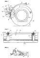
- FIG. 8 shows a basically known Kehrblasmaschine 15, which is used in particular for removing snow from the surface 5 to be cleaned.
- the sweeper for this purpose has a sweeping brush 10, which is arranged as a substantially cylindrical roller and is rotationally driven in the direction of the arrow shown.
- the sweeping brush 10 may have a width of several meters and is provided with sweeping bristles of steel and / or plastic.
- a rigid shield which prevents the sweeping brush mitgeschörderten snow that dissolves from the sweeping brush, to be thrown free upwards.
- This and the other known shields have the disadvantages mentioned in the introduction.
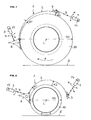
- FIG. 1 shows a state in which the sweeping brush is new or practically new and has the diameter D1.
- FIG. 2 shows a practically completely worn sweeping brush, in which the diameter is only D2.
- the sweeping brush cover in this case has a non-rigid, elastically bendable, or curved, plate-shaped shield element 2, which is bent to adapt to the substantially cylindrical shape of the sweeping brush roller.
- the elastic plate-shaped element 2 covers the sweeping brush in its upper region and extends from the inlet side E to the outlet side A.
- a wedge-shaped element 6 is provided on the inlet side, which, seen in the direction of rotation of the brush, before the element 2 comes to rest and thus forms the inlet E in this embodiment.
- the elastically, and seen from the longitudinal axis L of the sweeping brush ago, convexly curved element 2 is held by adjusting means and is adjustable by this in its curvature or curvature.
- the elastic element 2 may consist of a metal sheet, but is preferably formed of a plastic material. In this case, preferably an ultra-high molecular weight polyethylene is used, which for example has a molecular weight of> 5x10 6 g / mol. Such a material, the material TIVAR® ® is eg 1000 from Quadrant.
- the curved plate-shaped element 2 can in the basic form of FIG. 1 be bent for the sweeping brush with the basic diameter D1, so that the element 2, the in FIG. 1 has shown basic form and this retains itself and starting from this until the further bent shape of FIG. 2 is deformed by the adjustment.
- the element 2 can not be pre-bent and thus flat, so that the curved shape of FIG. 1 imposed by the adjustment and is maintained by this and the element 2 would spring back into its planar basic shape, if it were not held by the adjusting means in the curved shape.
- the adjusting effect the further curvature to the maximum curved end position of the FIG. 2 ,
- the adjusting means are shown schematically and have the means 3 and 4, which are each driven to pivot about axes 13 and 14, as this is indicated by the arrows a, or which are driven by means of shafts 13, 14 are pivotally driven accordingly.
- the adjusting means 3, 4 longitudinally adjustable members, which are adjustable according to the arrows b in their length adjustable.
- the adjusting means 3 engages the inlet-side wedge 6. This is just an example. If no wedge 6 is provided, the adjusting means acts essentially directly on the element 2. Such is shown for the adjusting means 4, which acts on the outlet side of the element 2 via a holder 7. This holder 7 may be attached to the element 2 in any manner.
- FIG. 2 shows correspondingly reduced to its minimum usable diameter D2 sweeping brush. It can be seen that by pivoting the adjusting means 3 upwards and Longitudinal adjustment of the adjusting means 3, the element 2 on the inlet side gradually more and more to adapt to the decreasing diameter of the sweeping brush is bent. At the same time takes place with the adjusting means 4, which is pivoted downwards and also driven in its length, a bend of the element 2 within its elastic bending range for adjusting the outlet side of the element 2 to the decreasing sweeping brush diameter.
- the bending is preferably carried out in such a way that the cavity between the sweeping brush circumference and the sweeping brush directed towards the inside of the curved element 3 from the inlet side to the outlet side is greater.
- this is shown with the two distances d1 and d2, which show this preferred adjustment of the adjusting means and the sweeping brush cover both with a large sweeping brush diameter and with a low sweeping brush diameter. Since, however, by the adjusting means within the limits of the bending stress of the element 2 whose curvature is freely selectable, a different geometry of the cavity can be selected. For the discharge-side removal of the snow swept by the sweeping brush, however, the preferred embodiment is the most suitable.
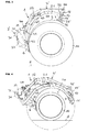
- FIGS. 3 to 6 show, again in side view, a preferred embodiment of the adjusting means for bending the element.
- FIG. 7 shows the corresponding embodiment in a view from above of the sweeping brush 10 and the sweeping brush cover 1.
- the longitudinal extent of the sweeping brush 10 in FIG. 7 clearly visible and it is shown that in each case left and right of the sweeping brush 10 and the element 2 are arranged adjusting means.
- the FIGS. 3 and 4 show the adjusting completely or show the adjustment means for the inlet side and the outlet side.
- FIGS. 3 to 7 the inlet-side adjusting means 3 'is formed by a first parallelogram and the outlet-side adjusting means 4' is formed by a second parallelogram.
- the outlet-side adjusting means 4' is formed by a second parallelogram.
- FIG. 7 shows a preferred embodiment, wherein in each case two parallelogram 4 'are combined with one drive 12 and accordingly also two parallelogram 3', which, however, in FIG. 7 are not designated.
- a larger number of adjusting means could be provided, so in particular another pair of parallelogram arrangements, which eg in FIG. 7 centered would be.
- the mentioned drive 12 which is formed in each case by a pneumatic cylinder or hydraulic cylinder or electric drive or a hand crank drive, engages on the one hand on a stationary, in particular fixed to the chassis of the sweeping brush assembly connectable or connected, support 11, which also provides axes of rotation for the Parallelogramman extract ,
- the drive 12 is pivotally mounted about the axis 40 to the support 11.
- the drive 12 is also pivotable about the axis 43 connected to the lower parallelogram 20 of the parallelogram 4 '. This has an upper parallelogram 21.
- the upper lever 21 is rotatably connected to the support 11 via the axis 41, while the lower lever 20 is rotatably connected to this support 11 via the axis 42.
- the upper parallelogram assembly 4 'for the outlet side of the element 2 is closed by the lever 22, which is connected by means of the axes 46 and 47 pivotally connected to the upper lever 21 and to the lower lever 20.
- An extension of the lever 22 is pivotally attached to the bracket 7 via the axle 28, which is fixed to the element 2. This is so in FIG. 5 shown.
- a preferred modification is shown in which the holder 7 is given an additional rotation about the axis of rotation 28 'in order to allow an even better adaptation of the outlet side of the element 2 by an additional bending of the outlet region of the element 2.
- a lever 17 is provided with the axis of rotation 17 ', which causes via pins 18 and 19 and the lever 16, a corresponding rotation of the holder 7 from the Parallelogrammamba, as compared in the FIGS. 3 and 4 is easy to see.
- a rotation could also be effected by a separate drive or another arrangement of the levers 16, 17.
- FIGS. 3 and 4 show the upper parallelogram 4 'separately in the two extreme positions for the non-worn sweeping brush 10 and for the virtually completely worn sweeping brush.
- FIG. 5 on the other hand, for better understanding, the parallelogram arrangement 4 'and the two sweeping brush diameters are shown in the same figure. Accordingly, two surfaces 5 are shown.
- the parallelogram 4 is shown with solid lines for the large sweeping brush diameter and with broken lines for the small sweeping brush diameter. It can be seen how, by adjusting the parallelogram, the element 2 moves on the outlet side and thus is increasingly bent starting from the position with a large sweeping brush diameter, wherein in addition the outlet side is adapted to the decreasing sweeping brush diameter. In the FIGS. 3 and 4 can be seen how this is effected by the extension of the drive element 12.
- FIGS. 3 and 4 and in particular for better illustration in the FIG. 6
- the lower parallelogram 3 'can be seen which has a first lever 30 which is articulated via a pivot axis 31 on the fixed support 11 and is attached via a further pivot axis 32 to the element 2, which in the illustrated Example via the wedge 6, which is attached to the element 2.
- the second lever 33 of the parallelogram 3 ' is articulated via the axis 34 pivotally mounted on the fixed support 11 and on the axis 35 in turn on the element 2 and in this embodiment on the wedge 6.
- FIG. 6 clearly seen how the parallelogram 3 'moves the wedge 6 substantially parallel to the surface 5 and the element 2 increasingly convex bends with decreasing sweeping brush diameter and the inlet side of the change in size of the brush tracks.
- FIGS. 3 and 4 it can be seen that the two parallelogram assemblies 3 'and 4' are drive-connected, so that the drive 12 actuates both parallelogram arrangements. In the example shown, this is done via a connecting member 45 which engages with one end on the lower lever 20 of the parallelogram 4 ', this in the example shown on the axis 43, and which is hinged at its other end to the lever 33, this over an axis 46th
- the flexible element 2 is in the illustrated embodiments, a single and integrally formed element, which is preferred.
- the element could, however, too be made of several parts, so in particular along the length of the sweeping brush 10 consist of several individual sections with their own adjusting means.
Landscapes
- Engineering & Computer Science (AREA)
- Architecture (AREA)
- Civil Engineering (AREA)
- Structural Engineering (AREA)
- Brushes (AREA)
Abstract
Description
Die Erfindung betrifft eine Kehrbürstenabdeckung gemäss Oberbegriff des Anspruchs 1. Ferner betrifft die Erfindung eine Kehrbürstenanordnung mit einer solchen Kehrbürstenabdeckung und ein so ausgerüstetes Kehrfahrzeug. Weiter betrifft die Erfindung ein Verfahren zur Abdeckung einer Kehrbürste.The invention relates to a sweeping brush cover according to the preamble of
Bei Reinigungsfahrzeugen, insbesondere bei Kehrblasfahrzeugen zur Schneeräumung, kommen grosse, walzen- bzw. zylinderförmige Kehrbürsten zum Einsatz. Diese Kehrbürsten mit Borsten aus Stahl oder Kunststoff können mehrere Meter lang sein und werden mit erheblichen Drehzahlen betrieben und die entsprechend ausgerüsteten Kehrfahrzeuge werden z.B. zur Schneeräumung auf Flughafenpisten oder auf Strassen eingesetzt. Ein solches Fahrzeug ist z.B. aus
Der Erfindung liegt die Aufgabe zu Grunde, eine Kehrbürstenabdeckung zu schaffen, welche diese Nachteile nicht aufweist.The invention is based on the object to provide a sweeping brush cover which does not have these disadvantages.
Dies wird bei der Kehrbürstenabdeckung der eingangs genannten Art mit den kennzeichnenden Merkmalen des Anspruchs 1 erreicht.This is achieved in the sweeping brush cover of the type mentioned above with the characterizing features of
Durch ein biegbares Schildelement und die Verstellmittel kann eine sehr gute Anpassung der Abdeckung bzw. deren Wölbung an die jeweilige Bürstengrösse erfolgen, ohne dass dabei "Ecken" bzw. unerwünschte Hohlräume verschiedener Form oberhalb der Bürste entstehen. Im Gegenteil ist eine genaue Formanpassung durch das Biegen möglich und es kann ein sich progressiv in Förderrichtung öffnender Spalt zwischen Abdeckung und Bürste durch die Verstellmittel erzeugt werden. Die glatte, ohne Schwenkachsen ausgeführte innere Oberfläche des elastisch biegbaren Schildelementes begünstigt das Abführen des Schnees.By means of a bendable shield element and the adjustment means, a very good adaptation of the cover or its curvature to the respective brush size can take place without "corners" or undesirable cavities of different shape arising above the brush. On the contrary, a precise shape adjustment by the bending is possible and it can be generated by the adjusting means a gap which opens progressively in the conveying direction between the cover and the brush. The smooth, running without pivot axes inner surface of the elastically bendable shield element favors the removal of the snow.
Bevorzugterweise ist das Schildelement aus einem Kunststoff gebildet, was eine gewichtsmässig vorteilhafte Abdeckung ergibt und ohne hohen Bearbeitungsaufwand bei der Herstellung eine glatte Oberfläche bereitstellen kann, an welcher Schnee nicht haftet. Bevorzugt findet ein ultrahochmolekulares Polyethylen Verwendung, allenfalls mit einem verschleissoptimierenden Zusatz, insbesondere aus Glaspartikeln.Preferably, the shield element is formed from a plastic, which results in a cover which is advantageous in terms of weight and can provide a smooth surface without high processing costs during manufacture, to which snow does not adhere. Preferably, an ultra-high molecular weight polyethylene is used, if necessary with a wear-optimizing additive, in particular of glass particles.
Bevorzugt weisen die Verstellmittel Führungen auf, insbesondere zwei gekoppelte Parallelogrammführungen, welche das vordere und das hintere Ende des Schutzschildelementes im Verlauf der Biegung zur Anpassung an den Durchmesser der Kehrbürste so verstellen, dass sich bei den meisten oder allen Biegestellungen ein sich stetig nach hinten zum Auslass erweiternder Hohlraum oberhalb der Kehrbürste ergibt. Solche Verstellmittel haben den Vorteil, dass sie wenig Einbauraum oberhalb der Bürste benötigen. Bevorzugt sind die Verstellmittel ferner so ausgeführt, dass auslassseitig eine Drehung des Elements erfolgt, um dieses noch besser an die Kehrbürstenform anzupassen.Preferably, the adjusting means on guides, in particular two coupled parallelogram guides, which adjust the front and the rear end of the shield element in the course of bending to adapt to the diameter of the sweeping brush so that in most or all bending situations, there is a cavity extending continuously rearward to the outlet above the sweeping brush. Such adjustment means have the advantage that they require little installation space above the brush. Preferably, the adjusting means are further designed so that the outlet side, a rotation of the element takes place in order to better adapt to the sweeping brush shape.
Der Erfindung liegt weiter die Aufgabe zu Grunde, eine Kehrbürstenanordnung sowie ein Kehrfahrzeug zu schaffen, welche die genannten Nachteile nicht aufweisen.The invention is further based on the object to provide a sweeping brush assembly and a sweeper, which do not have the disadvantages mentioned.
Diese Aufgaben werden mit den Merkmalen des Anspruchs 11 bzw. des Anspruchs 12 gelöst; ein Verfahren zur Abdeckung einer Kehrbürste ist durch Anspruch 13 definiert.These objects are achieved with the features of
Im Folgenden werden Ausführungsbeispiele der Erfindung anhand der Zeichnungen näher erläutert. Dabei zeigt
-
Figur 1 -
Figur 2Figur 1 -
Figur 3 -
Figur 4Figur 3 -
Figur 5Figuren 3 und 4 -
Figur 6Figuren 3 und 4 -
Figur 7 eine Ansicht auf eine Kehrbürste und eine Kehrbürstenabdeckung von oben; und -
Figur 8 eine Darstellung eines Kehrblasfahrzeuges in Seitenansicht.
-
FIG. 1 in a schematic side view of a sweeping brush when new with a cover according to the invention; -
FIG. 2 the schematic representation ofFIG. 1 with worn sweeping brush; -
FIG. 3 a schematic side view of a sweeping brush when new and a cover with adjusting means formed by Parallelogrammanordnungen; -
FIG. 4 the view ofFIG. 3 with worn sweeping brush; -
FIG. 5 the embodiment of theFIGS. 3 and 4 with the upper parallelogram in the two end positions; -
FIG. 6 the embodiment of theFIGS. 3 and 4 with the lower parallelogram in the two end positions; -
FIG. 7 a view of a sweeping brush and a sweeping brush cover from above; and -
FIG. 8 a representation of a Kehrblasfahrzeuges in side view.
Im Folgenden wird das erfindungsgemässe Schutzschild, bzw. die Kehrbürstenabdeckung 1 anhand der
Anhand der
In den
Ausgehend von dem Durchmesser D1 von
Die
Mit den
In den
In den
Das biegsame Element 2 ist in den dargestellten Ausführungen ein einziges und einstückig ausgeführtes Element, was bevorzugt ist. Das Element könnte indes auch aus mehreren Teilen ausgeführt sein, so insbesondere entlang der Länge der Kehrbürste 10 aus mehreren einzelnen Abschnitten mit eigenen Verstellmitteln bestehen.The
Claims (16)
Priority Applications (1)
| Application Number | Priority Date | Filing Date | Title |
|---|---|---|---|
| EP08010782A EP2133473A1 (en) | 2008-06-13 | 2008-06-13 | Sweeping brush cover and sweeping machine with such a cover |
Applications Claiming Priority (1)
| Application Number | Priority Date | Filing Date | Title |
|---|---|---|---|
| EP08010782A EP2133473A1 (en) | 2008-06-13 | 2008-06-13 | Sweeping brush cover and sweeping machine with such a cover |
Publications (1)
| Publication Number | Publication Date |
|---|---|
| EP2133473A1 true EP2133473A1 (en) | 2009-12-16 |
Family
ID=39884937
Family Applications (1)
| Application Number | Title | Priority Date | Filing Date |
|---|---|---|---|
| EP08010782A Withdrawn EP2133473A1 (en) | 2008-06-13 | 2008-06-13 | Sweeping brush cover and sweeping machine with such a cover |
Country Status (1)
| Country | Link |
|---|---|
| EP (1) | EP2133473A1 (en) |
Citations (7)
| Publication number | Priority date | Publication date | Assignee | Title |
|---|---|---|---|---|
| US501352A (en) * | 1893-07-11 | Street-sweeper | ||
| US2700783A (en) * | 1953-07-16 | 1955-02-01 | Parker Sweeper Company | Adjustable hood for sweepers |
| US3212118A (en) * | 1962-10-19 | 1965-10-19 | Charles C Anderson | Road sweeper |
| US3287834A (en) * | 1964-04-06 | 1966-11-29 | Eithel G Hopkins | Motor grader mold board attachment |
| DE2161485A1 (en) * | 1970-12-10 | 1972-06-29 | Dendix Brushes Ltd., Chepstow, Monmouthshire (Großbritannien) | Snow removal device |
| EP0288436A1 (en) | 1987-04-23 | 1988-10-26 | Reberle reg. Treuunternehmen Schaan | Apparatus for cleaning hard top ground surfaces |
| US6311355B1 (en) * | 2000-09-05 | 2001-11-06 | Pairia Vammas Oy | Sweeper |
-
2008
- 2008-06-13 EP EP08010782A patent/EP2133473A1/en not_active Withdrawn
Patent Citations (7)
| Publication number | Priority date | Publication date | Assignee | Title |
|---|---|---|---|---|
| US501352A (en) * | 1893-07-11 | Street-sweeper | ||
| US2700783A (en) * | 1953-07-16 | 1955-02-01 | Parker Sweeper Company | Adjustable hood for sweepers |
| US3212118A (en) * | 1962-10-19 | 1965-10-19 | Charles C Anderson | Road sweeper |
| US3287834A (en) * | 1964-04-06 | 1966-11-29 | Eithel G Hopkins | Motor grader mold board attachment |
| DE2161485A1 (en) * | 1970-12-10 | 1972-06-29 | Dendix Brushes Ltd., Chepstow, Monmouthshire (Großbritannien) | Snow removal device |
| EP0288436A1 (en) | 1987-04-23 | 1988-10-26 | Reberle reg. Treuunternehmen Schaan | Apparatus for cleaning hard top ground surfaces |
| US6311355B1 (en) * | 2000-09-05 | 2001-11-06 | Pairia Vammas Oy | Sweeper |
Similar Documents
| Publication | Publication Date | Title |
|---|---|---|
| DE3528038C2 (en) | ||
| EP2339072B1 (en) | Rear milling cutter for a snow groomer | |
| EP2213183A1 (en) | Device for providing filter tow material and device for producing filters | |
| DE102015209852A1 (en) | Door handle system for a motor vehicle door | |
| DE102017113775A1 (en) | Draper cutting unit with multipiece auger | |
| EP2021548B1 (en) | Waved clearing bar | |
| DE29603461U1 (en) | Halfpiperreamer | |
| DE3226273C2 (en) | Snow blower | |
| EP3097763B1 (en) | Vehicle with articulated steering and suction hose | |
| DE10062329C1 (en) | Suction sweeping unit | |
| EP1925746B1 (en) | Piste preparation device for a tracked vehicle | |
| EP3727955B1 (en) | Arrangement of nozzle units for a wiper arm, wiper arm and use of a nozzle unit | |
| WO2010052145A1 (en) | Segment body and scraper for a conveyor belt scraper | |
| EP1824716A1 (en) | Wiper system | |
| AT412003B (en) | SNOW PLOW WITH A MULTIPLE SHARE SEGMENT | |
| EP3243961B1 (en) | Universal slider for cleaning of floor | |
| DE102011018868B4 (en) | Conveyor | |
| EP2133473A1 (en) | Sweeping brush cover and sweeping machine with such a cover | |
| DE60102095T2 (en) | Motorized sweeper | |
| EP4491804A1 (en) | Milling box with snow flow regulation system for snow-operated vehicles | |
| DE19856338B4 (en) | Scraper for conveyor belts | |
| EP1254593B1 (en) | Soil working tool for comminuting coarsely worked fields | |
| EP1342402B1 (en) | Method for adjusting guiding plates and chopper to carry out the method | |
| EP3284866B1 (en) | Clearing device with a sweeping and blowing assembly | |
| DE202017102036U1 (en) | Front sweeping unit with a suction mouth |
Legal Events
| Date | Code | Title | Description |
|---|---|---|---|
| PUAI | Public reference made under article 153(3) epc to a published international application that has entered the european phase |
Free format text: ORIGINAL CODE: 0009012 |
|
| AK | Designated contracting states |
Kind code of ref document: A1 Designated state(s): AT BE BG CH CY CZ DE DK EE ES FI FR GB GR HR HU IE IS IT LI LT LU LV MC MT NL NO PL PT RO SE SI SK TR |
|
| AX | Request for extension of the european patent |
Extension state: AL BA MK RS |
|
| AKY | No designation fees paid | ||
| REG | Reference to a national code |
Ref country code: DE Ref legal event code: 8566 |
|
| STAA | Information on the status of an ep patent application or granted ep patent |
Free format text: STATUS: THE APPLICATION IS DEEMED TO BE WITHDRAWN |
|
| 18D | Application deemed to be withdrawn |
Effective date: 20100617 |