EP2133627A2 - Vorrichtung zur Rückgewinnung der Rauchwärme und Entladung von Verbrennungsrauch für einen Boiler - Google Patents
Vorrichtung zur Rückgewinnung der Rauchwärme und Entladung von Verbrennungsrauch für einen Boiler Download PDFInfo
- Publication number
- EP2133627A2 EP2133627A2 EP09162482A EP09162482A EP2133627A2 EP 2133627 A2 EP2133627 A2 EP 2133627A2 EP 09162482 A EP09162482 A EP 09162482A EP 09162482 A EP09162482 A EP 09162482A EP 2133627 A2 EP2133627 A2 EP 2133627A2
- Authority
- EP
- European Patent Office
- Prior art keywords
- tubular element
- heat
- fume
- fumes
- boiler
- Prior art date
- Legal status (The legal status is an assumption and is not a legal conclusion. Google has not performed a legal analysis and makes no representation as to the accuracy of the status listed.)
- Withdrawn
Links
- 239000003517 fume Substances 0.000 title claims abstract description 108
- 238000011084 recovery Methods 0.000 title claims abstract description 37
- 238000002485 combustion reaction Methods 0.000 title abstract description 20
- XLYOFNOQVPJJNP-UHFFFAOYSA-N water Substances O XLYOFNOQVPJJNP-UHFFFAOYSA-N 0.000 claims abstract description 27
- 238000010438 heat treatment Methods 0.000 claims abstract description 13
- 230000001105 regulatory effect Effects 0.000 claims 1
- 239000003546 flue gas Substances 0.000 description 8
- 238000009434 installation Methods 0.000 description 6
- 238000004891 communication Methods 0.000 description 3
- 238000011144 upstream manufacturing Methods 0.000 description 3
- UGFAIRIUMAVXCW-UHFFFAOYSA-N Carbon monoxide Chemical compound [O+]#[C-] UGFAIRIUMAVXCW-UHFFFAOYSA-N 0.000 description 2
- 230000000694 effects Effects 0.000 description 2
- 230000008030 elimination Effects 0.000 description 2
- 238000003379 elimination reaction Methods 0.000 description 2
- 239000000463 material Substances 0.000 description 2
- 230000002829 reductive effect Effects 0.000 description 2
- 238000009877 rendering Methods 0.000 description 2
- 239000004411 aluminium Substances 0.000 description 1
- 229910052782 aluminium Inorganic materials 0.000 description 1
- XAGFODPZIPBFFR-UHFFFAOYSA-N aluminium Chemical compound [Al] XAGFODPZIPBFFR-UHFFFAOYSA-N 0.000 description 1
- 238000005266 casting Methods 0.000 description 1
- 230000002860 competitive effect Effects 0.000 description 1
- 238000009833 condensation Methods 0.000 description 1
- 230000005494 condensation Effects 0.000 description 1
- 238000010276 construction Methods 0.000 description 1
- 230000002349 favourable effect Effects 0.000 description 1
- 239000000446 fuel Substances 0.000 description 1
- 239000007789 gas Substances 0.000 description 1
- 230000005484 gravity Effects 0.000 description 1
- 239000008236 heating water Substances 0.000 description 1
- 238000004519 manufacturing process Methods 0.000 description 1
- 239000002184 metal Substances 0.000 description 1
- 229910052751 metal Inorganic materials 0.000 description 1
- 239000007769 metal material Substances 0.000 description 1
- 238000005192 partition Methods 0.000 description 1
Images




Classifications
-
- F—MECHANICAL ENGINEERING; LIGHTING; HEATING; WEAPONS; BLASTING
- F23—COMBUSTION APPARATUS; COMBUSTION PROCESSES
- F23J—REMOVAL OR TREATMENT OF COMBUSTION PRODUCTS OR COMBUSTION RESIDUES; FLUES
- F23J13/00—Fittings for chimneys or flues
- F23J13/02—Linings; Jackets; Casings
- F23J13/025—Linings; Jackets; Casings composed of concentric elements, e.g. double walled
-
- F—MECHANICAL ENGINEERING; LIGHTING; HEATING; WEAPONS; BLASTING
- F23—COMBUSTION APPARATUS; COMBUSTION PROCESSES
- F23J—REMOVAL OR TREATMENT OF COMBUSTION PRODUCTS OR COMBUSTION RESIDUES; FLUES
- F23J15/00—Arrangements of devices for treating smoke or fumes
- F23J15/06—Arrangements of devices for treating smoke or fumes of coolers
-
- F—MECHANICAL ENGINEERING; LIGHTING; HEATING; WEAPONS; BLASTING
- F24—HEATING; RANGES; VENTILATING
- F24D—DOMESTIC- OR SPACE-HEATING SYSTEMS, e.g. CENTRAL HEATING SYSTEMS; DOMESTIC HOT-WATER SUPPLY SYSTEMS; ELEMENTS OR COMPONENTS THEREFOR
- F24D12/00—Other central heating systems
- F24D12/02—Other central heating systems having more than one heat source
-
- F—MECHANICAL ENGINEERING; LIGHTING; HEATING; WEAPONS; BLASTING
- F28—HEAT EXCHANGE IN GENERAL
- F28D—HEAT-EXCHANGE APPARATUS, NOT PROVIDED FOR IN ANOTHER SUBCLASS, IN WHICH THE HEAT-EXCHANGE MEDIA DO NOT COME INTO DIRECT CONTACT
- F28D21/00—Heat-exchange apparatus not covered by any of the groups F28D1/00 - F28D20/00
- F28D21/0001—Recuperative heat exchangers
- F28D21/0003—Recuperative heat exchangers the heat being recuperated from exhaust gases
- F28D21/0005—Recuperative heat exchangers the heat being recuperated from exhaust gases for domestic or space-heating systems
- F28D21/0007—Water heaters
-
- F—MECHANICAL ENGINEERING; LIGHTING; HEATING; WEAPONS; BLASTING
- F28—HEAT EXCHANGE IN GENERAL
- F28D—HEAT-EXCHANGE APPARATUS, NOT PROVIDED FOR IN ANOTHER SUBCLASS, IN WHICH THE HEAT-EXCHANGE MEDIA DO NOT COME INTO DIRECT CONTACT
- F28D7/00—Heat-exchange apparatus having stationary tubular conduit assemblies for both heat-exchange media, the media being in contact with different sides of a conduit wall
- F28D7/06—Heat-exchange apparatus having stationary tubular conduit assemblies for both heat-exchange media, the media being in contact with different sides of a conduit wall the conduits having a single U-bend
-
- F—MECHANICAL ENGINEERING; LIGHTING; HEATING; WEAPONS; BLASTING
- F28—HEAT EXCHANGE IN GENERAL
- F28F—DETAILS OF HEAT-EXCHANGE AND HEAT-TRANSFER APPARATUS, OF GENERAL APPLICATION
- F28F1/00—Tubular elements; Assemblies of tubular elements
- F28F1/10—Tubular elements and assemblies thereof with means for increasing heat-transfer area, e.g. with fins, with projections, with recesses
- F28F1/12—Tubular elements and assemblies thereof with means for increasing heat-transfer area, e.g. with fins, with projections, with recesses the means being only outside the tubular element
- F28F1/14—Tubular elements and assemblies thereof with means for increasing heat-transfer area, e.g. with fins, with projections, with recesses the means being only outside the tubular element and extending longitudinally
- F28F1/16—Tubular elements and assemblies thereof with means for increasing heat-transfer area, e.g. with fins, with projections, with recesses the means being only outside the tubular element and extending longitudinally the means being integral with the element, e.g. formed by extrusion
-
- F—MECHANICAL ENGINEERING; LIGHTING; HEATING; WEAPONS; BLASTING
- F28—HEAT EXCHANGE IN GENERAL
- F28F—DETAILS OF HEAT-EXCHANGE AND HEAT-TRANSFER APPARATUS, OF GENERAL APPLICATION
- F28F1/00—Tubular elements; Assemblies of tubular elements
- F28F1/10—Tubular elements and assemblies thereof with means for increasing heat-transfer area, e.g. with fins, with projections, with recesses
- F28F1/42—Tubular elements and assemblies thereof with means for increasing heat-transfer area, e.g. with fins, with projections, with recesses the means being both outside and inside the tubular element
-
- F—MECHANICAL ENGINEERING; LIGHTING; HEATING; WEAPONS; BLASTING
- F28—HEAT EXCHANGE IN GENERAL
- F28F—DETAILS OF HEAT-EXCHANGE AND HEAT-TRANSFER APPARATUS, OF GENERAL APPLICATION
- F28F1/00—Tubular elements; Assemblies of tubular elements
- F28F1/10—Tubular elements and assemblies thereof with means for increasing heat-transfer area, e.g. with fins, with projections, with recesses
- F28F1/42—Tubular elements and assemblies thereof with means for increasing heat-transfer area, e.g. with fins, with projections, with recesses the means being both outside and inside the tubular element
- F28F1/422—Tubular elements and assemblies thereof with means for increasing heat-transfer area, e.g. with fins, with projections, with recesses the means being both outside and inside the tubular element with outside means integral with the tubular element and inside means integral with the tubular element
-
- F—MECHANICAL ENGINEERING; LIGHTING; HEATING; WEAPONS; BLASTING
- F23—COMBUSTION APPARATUS; COMBUSTION PROCESSES
- F23J—REMOVAL OR TREATMENT OF COMBUSTION PRODUCTS OR COMBUSTION RESIDUES; FLUES
- F23J2211/00—Flue gas duct systems
- F23J2211/10—Balanced flues (combining air supply and flue gas exhaust)
- F23J2211/101—Balanced flues (combining air supply and flue gas exhaust) with coaxial duct arrangement
-
- F—MECHANICAL ENGINEERING; LIGHTING; HEATING; WEAPONS; BLASTING
- F24—HEATING; RANGES; VENTILATING
- F24D—DOMESTIC- OR SPACE-HEATING SYSTEMS, e.g. CENTRAL HEATING SYSTEMS; DOMESTIC HOT-WATER SUPPLY SYSTEMS; ELEMENTS OR COMPONENTS THEREFOR
- F24D2200/00—Heat sources or energy sources
- F24D2200/16—Waste heat
- F24D2200/18—Flue gas recuperation
-
- Y—GENERAL TAGGING OF NEW TECHNOLOGICAL DEVELOPMENTS; GENERAL TAGGING OF CROSS-SECTIONAL TECHNOLOGIES SPANNING OVER SEVERAL SECTIONS OF THE IPC; TECHNICAL SUBJECTS COVERED BY FORMER USPC CROSS-REFERENCE ART COLLECTIONS [XRACs] AND DIGESTS
- Y02—TECHNOLOGIES OR APPLICATIONS FOR MITIGATION OR ADAPTATION AGAINST CLIMATE CHANGE
- Y02B—CLIMATE CHANGE MITIGATION TECHNOLOGIES RELATED TO BUILDINGS, e.g. HOUSING, HOUSE APPLIANCES OR RELATED END-USER APPLICATIONS
- Y02B30/00—Energy efficient heating, ventilation or air conditioning [HVAC]
-
- Y—GENERAL TAGGING OF NEW TECHNOLOGICAL DEVELOPMENTS; GENERAL TAGGING OF CROSS-SECTIONAL TECHNOLOGIES SPANNING OVER SEVERAL SECTIONS OF THE IPC; TECHNICAL SUBJECTS COVERED BY FORMER USPC CROSS-REFERENCE ART COLLECTIONS [XRACs] AND DIGESTS
- Y02—TECHNOLOGIES OR APPLICATIONS FOR MITIGATION OR ADAPTATION AGAINST CLIMATE CHANGE
- Y02E—REDUCTION OF GREENHOUSE GAS [GHG] EMISSIONS, RELATED TO ENERGY GENERATION, TRANSMISSION OR DISTRIBUTION
- Y02E20/00—Combustion technologies with mitigation potential
- Y02E20/30—Technologies for a more efficient combustion or heat usage
Definitions
- the present invention relates to a device for recovery of the fume heat and discharge of combustion fumes for a boiler normally used in the domestic or industrial sectors.
- the invention likewise regards a heating assembly comprising a boiler and a device for recovery of fume heat and discharge of fumes according to the invention connected to said boiler.
- boilers are thermal apparatuses traditionally used for heating water that is to be introduced into a heating circuit or else to be used for sanitary purposes for the personal requirements of users.
- Boilers traditionally comprise a combustion chamber, housed in the proximity of which is a heat exchanger, referred to as primary heat exchanger, in order to provide for heating of water.
- the fumes produced following upon combustion possess, as is known, a high thermal energy, which can advantageously be recovered in order to pre-heat the water entering the primary heat exchanger. This enables limitation of the amount of fuel consumed in so far as the thermal jump required becomes smaller given the same final temperature required for the water leaving the boiler.
- devices are traditionally used for recovery of fume heat, which are at times also referred to as "economizers”. They usually comprise heat exchangers (also referred to as secondary heat exchangers), located in most cases inside the boiler between the combustion chamber and a discharge mouth, at which pipes are inserted that convey the fumes into the atmosphere.
- heat exchangers also referred to as secondary heat exchangers
- the secondary heat exchanger is constituted by a bank of tubes housed in a container inside the boiler casing.
- the tubes are internally traversed by water and are externally lapped by the combustion fumes conveyed within the container by means of a fan.
- a convective-conductive heat exchange the thermal energy of the flue gas is transferred from the flue gas to the water.
- the solution illustrated envisages the use of a partition wall, which, by separating the inlet of the flue gases from the outlet, enables them to follow a predefined path.
- the thermal energy of the flue gases is recovered through heat exchangers that are positioned in the flue of the boiler.
- the patent application No. WO 2006/059215 describes a device (100) for discharge of fumes of a domestic boiler, said device being provided with a tubular element, housed in which are heat-exchanger means (105) for transferring the thermal energy of the flue gases to the circuit for the water that is to enter the primary heat exchanger of the boiler.
- the device in question is connected to a boiler (150) through a flange adapter (130), which also configures a system for discharge of the condensate that forms within the tubular elements.
- the heat-exchanger means (105) are basically formed by a heat-exchange tube, defined within which are two cavities designed to be traversed in opposite directions by water to be heated.
- the solution in question revealed various drawbacks. It has been seen, in fact, that the efficiency of the heat exchange enabled by the heat-exchanger means is rather limited in part on account of the configuration of the heat-exchange elements and in part on account of the conditions of outflow of the fumes within the tubular discharge element.
- the current configuration of the heat-exchanger means limits the efficiency of the conductive heat exchange between the metal surface of the heat-exchange elements and the water circulating therein. More precisely, it has been noted that the current configuration of the heat-exchanger elements enables effective heating of only rather modest amounts of water.
- the conditions of outflow of the fumes within the discharge tube involve, instead, the convective heat exchange between the flue gases and the heat-exchange elements themselves.
- Said flue gases are currently forced within the discharge tube by a fan located within the boiler. It has been noted that in many cases the action of the fan combined with the high temperature of the combustion fumes determines an excessively high rate of outlet of the flue gases, which renders insufficient the time useful for the convective exchange, consequently limiting the efficiency of said heat exchange.
- a purpose of the present invention is to provide a device for recovery of fume heat and discharge of fumes that will enable simplification of the design, as well as reduction of the encumbrance of the boilers to which the device itself can be applied.
- Another purpose of the present invention is to provide a device that will enable a more effective recovery of fume heat as compared to what was possible using traditional devices.
- Yet another purpose of the present invention is to provide a device that is obtained using a relatively contained number of components that can be easily assembled together.
- a further purpose of the present invention is to provide a device for recovery of fume heat and discharge of fumes, the configuration of which bestows thereon a high functional versatility above all in relation to the mode of connection to a boiler.
- a device for recovery of fume heat and discharge of fumes which is connectable to a boiler and comprises a first tubular element, which may be traversed by combustion fumes of a boiler.
- Said first tubular element comprises a fume-inlet section and a fume-discharge section opposite to the fume-inlet section.
- the device moreover comprises heat-exchanger means housed within the first tubular element for transferring at least part of the thermal energy of the fumes to the water at a lower temperature circulating within said heat-exchanger means.
- the device according to the invention is characterized in that it comprises means for intake of the fumes operatively located in the proximity of the fume-discharge section for sucking said fumes in the first tubular element through the fume-inlet section.
- intake means set operatively on the outside of a boiler advantageously enables simplification of the internal design of the boiler itself, to which the device for recovery of fume heat and discharge of fumes can be connected. It has been noted, in fact, that the possibility of eliminating the internal fan, deriving precisely from the external intake, leads to a reduction of the encumbrance in height of some tens of centimetres given the same layout of the other significant components of the boiler. This obviously contributes to rendering the boiler extremely versatile in so far as it increases the number of possible installations thereof.
- the device 1 for recovery of fume heat and discharge of fumes comprises at least one first tubular element 10, which is susceptible of being traversed by fumes generated in the combustion chamber of a boiler 2.
- Said first tubular element 10 has a fume-inlet section 11 and a fume-discharge section 12, substantially opposite to the fume-inlet section 11.
- the device 1 likewise comprises heat-exchanger means housed within the first tubular element 10.
- Said heat-exchanger means are prearranged for transferring thermal energy from the fumes, once these traverse the first tubular element 10, to the water to be heated, circulating in the heat-exchanger means themselves.
- the water circulating in the heat-exchanger means can advantageously be sent to the primary heat exchanger of the boiler 2 in order to improve the efficiency of the boiler itself.
- the water leaving the heat-exchanger means can be directly used for heating or for sanitary purposes.
- the device 1 is characterized in that it comprises intake means 5 operatively located in a position corresponding to the fume-discharge section 12 for sucking the fumes of the boiler 2 in the first tubular element 10 through the fume-inlet section 11.
- the intake means 5 hence have the purpose of aspiring the fumes of the boiler 2, preferably from the fluid-tight chamber thereof, into the first tubular element 10 to enable, on the one hand, controlled discharge of fumes into the atmosphere and, on the other, simultaneous recovery of the fume heat as a result of the heat-exchanger means.
- the intake means 5 comprise an adjustable-speed aspirator in order to increase the efficiency of the heat exchange.
- an adjustable-speed aspirator enables in fact regulation of the flow of the fumes within the first tubular element 10, in practice modulating the rate thereof.
- This means in effect controlling the time variable that notoriously affects the heat exchange and in particular the convective part thereof that occurs between the fumes and the walls of the heat-exchanger means.
- the possibility of prolonging the time of heat exchange has favourable repercussions on the heating of the water circulating in the heat-exchanger means.
- FIG. 2 is a view of the device 1 for recovery of fume heat and discharge of fumes according to the invention, connected to a boiler 2.
- the intake means 5 comprise an aspirator provided with an intake section 5B in communication with the fume-discharge section 12 of the first tubular element 10 and a with delivery section 5C in communication with the atmosphere.
- the device 1 for recovery of fume heat and discharge of fumes can advantageously develop so that the aspirator 5 is located in an environment 200 external to the boiler room 201, in which the boiler 2 to which the device itself is connected is located.
- the division of the two environments is represented schematically by a wall T represented as being made of masonry purely for purposes of illustration.
- the device 1 for recovery of fume heat and discharge of fumes preferably comprises a second tubular element 20, operatively located within which is the first tubular element 10 in such a way as to generate an annular space 25 for passage of air that is to go to the boiler 2 and that can be used as comburent in the combustion chamber of the boiler itself.
- the two tubular elements 10 and 20 are made preferably of metal material, for example aluminium.
- Each of the two tubular elements 10 and 20 comprises a longitudinal portion 14, 24 and a curved portion 13, 23 connected to one end of the corresponding longitudinal portion 14, 24.
- the use of a curved portion 13, 23 for each tubular element 10, 20 advantageously enables connection of the device to a boiler 2 and at the same time orientation thereof in space according to the requirements of use in order to facilitate location of the boiler 2 within the boiler room 201.
- the longitudinal portion 14 of the first tubular element 10 is configured for housing the heat-exchanger means and is located inside the longitudinal portion 24 of the second tubular element 20.
- said longitudinal portion 14 is housed so that its longitudinal axis 101 is inclined with respect to the longitudinal axis 102 of the longitudinal portion 24 of the second tubular element 20.
- This arrangement has the purpose of enabling the flow of the condensate (which forms as a result of the heat exchange) towards the curved portion 13 of the first tubular element 10, located in the proximity of which are discharge means for the condensate described hereinafter.
- the figure illustrates a device 1 for recovery of fume heat and discharge of fumes according to the invention in a substantially horizontal configuration of installation such that the longitudinal portion 24 of the second tubular element 20 is substantially parallel to a horizontal plane of reference O.
- the curved portion 23 of the second tubular element 20 is connected to a top surface S of the boiler 2 substantially parallel to the plane of reference O. Said connection is made through a flanged rim 29 defined at one free end of the curved portion 23, substantially opposite to the end connected to the corresponding longitudinal portion 24 of the second element 20.
- the mode of connection enables mechanical fixing of the entire device 1 to the boiler 2, but must be considered in any case merely as a possible, and consequently non-exclusive, technical solution.
- the device 1 could also be connected to the boiler 2 through a flanged rim made on a portion of the first tubular element 10 in a position close to the fume-inlet section 11.
- the curved portion 13 of the first tubular element 10 comprises a first part 16, which connects to one end of the longitudinal portion 14, and a second part 17, which defines the fume-inlet section 11.
- said second part 17 can extend beyond the flanged connection rim 29 from the curved portion 22 of the second tubular element 20.
- the device 1 of Figure 2 could also be installed according to a "vertical" configuration such that the flanged rim 29 is to be operatively connected to a lateral surface L of the boiler 2.
- the axis 102 of the longitudinal portion 24 of the second element 20 will be substantially orthogonal to the horizontal plane of reference O.
- the axes 101, 102 of the longitudinal portions 14, 24 of the two tubular elements 10, 20 could also coincide in so far as the flow of the condensate would be obtained by gravity as far as the condensate-discharge means.
- the two tubular elements 10 and 20 are without the curved portions 13, 23 illustrated in Figure 2 , i.e., made in the form of two tubes substantially inserted inside one another. Said configuration enables connection of the device 1 to one of the surfaces of the boiler 2 in such a way, for example, that the longitudinal axis 102 of the second element 20 is orthogonal to the surface, whether this be the top surface S or the lateral surface L.
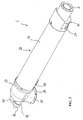
- Figures 3 and 4 are, respectively, a perspective view and a plan view of the device 1 for recovery of fume heat and discharge of fumes illustrated in Figure 2 .
- the device 1 is deprived, for purely descriptive purposes, of the intake means 5, and the second tubular element 20 is without the corresponding longitudinal portion 24 illustrated in Figure 2 .
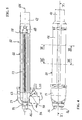
- Figure 5 is a cross-sectional view according to the line V-V of Figure 4 and illustrates the arrangement of the heat-exchanger means prearranged within the first tubular element 10.
- the heat-exchanger means comprise a plurality of heat-exchange elements 33, which are connected together in such a way as to configure a hydraulic circuit within the first tubular element 10.
- water is made to circulate, which is preferably, but non-exclusively, to be further heated by the boiler 2 to which the device 1 is connected.
- the hydraulic circuit according to the invention is configured so that the heat exchange between the fumes and the water occurs partially in conditions of equicurrent, i.e., when the direction of the water is concordant to that of the fumes, and partially in conditions of countercurrent, i.e., when the direction of flow of the water is opposite to that of the combustion fumes.
- the hydraulic circuit comprises at least one pair of elongated heat-exchange elements 33, which are hollow and are set at least partially in a longitudinal direction on the outer surface. Said elements 33 are located within the longitudinal portion 14 of the first tubular element 10 so that the longitudinal axis 101 of said portion is parallel to that of the axes of the single elements 33.
- each heat-exchange element 33 is operatively set so that one first terminal part thereof 38 is located within the first tubular element 10, whilst a second terminal part 39 opposite to the first 38 comes out of the first tubular element 10 and out of the second tubular element 20, traversing the corresponding curved portion 13, 23.
- each heat-exchange element 33 is provided with a hydraulic connection 46 that enables the elements 33 to be inserted in a hydraulic circuit, as may, for example, be that for supply of the boiler 2, as appears clearly from the representation of Figure 2 .
- the hydraulic circuit comprises a flow-reversal connector 47, which connects the corresponding first terminal portions 38 of the heat-exchange elements 33, which, as indicated, are internal to the first tubular element 10.
- Said radiusing 47 has the function of enabling a reversal of the direction of the flow of the water during passage thereof from one element to the other. In this way, the mode of heat exchange is varied, becoming from equicurrent to countercurrent.
- the flow-reversal connector 47 has a substantially U-shaped configuration, as may be appreciated from the cutaway view in Figure 6 , which shows in any case only one half of said radiusing 47.
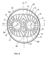
- Figures 7 and 8 are cross-sectional views, respectively, according to the line VII-VII and the line VIII-VIII of Figure 4 and show in detail the cross section of the longitudinal portion 14 of the first tubular element 10 and the cross section of the two heat-exchange elements 33 housed therein.
- the first tubular element 10 has an ellipsoidal cross section.
- the term "ellipsoidal" is intended to indicate a generic geometrical shape that "recalls” the shape of an ellipse (not necessarily coinciding with the definition of ellipse itself) and that is symmetrical with respect to two mutually orthogonal axes of symmetry X, Y.
- the cross section of the longitudinal portion 14 of the first element 10 is made up of two semicircular portions 58, which are symmetrical with respect to a first axis X and connected together through two rectilinear portions 59, which are opposed with respect to a second axis Y orthogonal to the first X.
- Each heat-exchange element 33 is formed by a tubular body 35 that defines a longitudinal cavity 71 for the passage of water.
- Each cavity 71 is delimited by an internal surface of a cylindrical shape, which has a plurality of radial projections 77 that develop preferably throughout the longitudinal development of the cavity 71.
- the two heat-exchange elements 33 are located within the first tubular element 10 so that the longitudinal axes 300 of the cavities 71 are aligned along the second axis of symmetry Y of the cross section, occupying at the same time a position symmetrical with respect to the first axis of symmetry X of the cross section itself.
- the tubular body 35 comprises a plurality of longitudinal fins 44, 45 that develop from its outer surface 36 in different directions.
- each tubular body 35 comprises a series of first longitudinal fins 44 that extend symmetrically with respect to the aforesaid second axis of symmetry Y from a first portion 36A (indicated in Figure 8 with a dashed line concentric to the portion in question) of the outer surface 36.
- said first fins 44 extend so as to occupy a position adjacent to the internal surface 14B of the longitudinal portion 14 of the first tubular element 10 and so as to be specular, with respect to the first axis X, to corresponding fins of the other element.
- each tubular body 35 moreover comprises a series of second longitudinal fins 45 that extend symmetrically from a second portion 36B (indicated in Figure 8 with a dashed line concentric to the portion in question) of the outer surface 36 with respect to the aforesaid second axis of symmetry Y.
- said second fins 45, of one of the two tubular bodies 35 extend so as to occupy a position specular with respect to corresponding second fins 45, of the other tubular body 35, with respect to the aforesaid first axis of symmetry X.
- each tubular body 35 moreover comprises a plurality of further radial projections 75, each of which emerges between two mutually adjacent longitudinal fins 44, 45. Said further radial projections preferably develop throughout the longitudinal extension of the tubular bodies 35.
- the geometrical configuration of the heat-exchange elements in particular the structure of the longitudinal fins 44, 45 and the presence of the radial projections 77, 75 enable, by virtue of the considerable surface available, a sensible improvement of the heat exchange between the combustion fumes and the water.
- an adapter 40 which defines the fume-discharge section 12 of the first tubular element 10.
- the intake means 5 of the device 1 according to the invention Installed in a position corresponding to said section 12 are the intake means 5 of the device 1 according to the invention. Consequently, the fume-discharge section 12 must be structured in the way most conformable to favour installation of said intake means. Consequently, it follows that the adapter 40 may advantageously be used as radiusing element between the cross section of the longitudinal portion 14 of the first tubular element 10 and the fume-discharge section 12, this being presumably different in geometry and/or dimensions.
- the adapter 40 is configured so as to adapt, upstream, to the elliptical cross section of the longitudinal stretch 14 defining, downstream, a substantially circular discharge section 12.
- the device 1 preferably comprises a supporting structure 91, which is connected to an outer end 27 of the longitudinal portion 21 of the second tubular element 20 opposite to the end connected to the corresponding curved portion 23.
- Said structure 91 is substantially ring-shaped and supports the first tubular element 10 in a position corresponding to the adapter 40.
- Said structure 91 is advantageously configured so as to provide a support also for the intake means 5, i.e., so as to install the latter in the most suitable operative position.
- the device 1 advantageously comprises means for discharge of the condensate that forms within the first tubular element 10 following upon the heat exchange between the fumes and the water circulating in the heat-exchanger means.
- Said condensate-discharge means preferably comprise an annular lip 51, which defines a path of collection of the condensate towards a discharge mouth 50 made on the curved portion 13 of the first tubular element 10.
- a discharge channel 55 which can advantageously convey the condensate out of the device 1 for recovery of fume heat and discharge of fumes.
- Said discharge channel 55 will advantageously be provided with siphon means that prevent exit of hot fumes from the device, enabling only discharge of the condensate when this exceeds a pre-set amount.
- the curved portion 13 of the first tubular element 10 must be structured in such a way as to be connectable downstream of the longitudinal portion 14, defining at the same time, upstream, the fume-inlet section 11. This may be defined in the way most conformable, for example, to the internal connection with the combustion chamber of the boiler.
- the first part 16 of the curved portion 13 is hence configured for connection, downstream, to the longitudinal portion 14 of the first tubular element 10, whilst the second part 17 defines, upstream, a substantially circular fume-inlet section 11.
- the present invention also relates to a heating assembly comprising a boiler 2 and a device 1 for recovery of fume heat and discharge of fumes according to the present invention. It has been seen that a heating assembly 3 thus conceived presents multiple advantages, above all in terms of overall thermal efficiency and in terms of reduction of the volumes of encumbrance associated to the boiler 2.
- the intake means 5 of the device 1 for recovery of fume heat and discharge of fumes enable a controlled intake of the discharged fumes produced by the boiler 2, in effect rendering use of the fans normally located within the boiler altogether unnecessary. This consequently leads to the possibility of designing and providing a boiler that is structurally simpler and more compact than the ones traditionally used.
- Common practice has in fact shown how elimination of the volumetric encumbrance linked to the presence of the fan can advantageously result in a possible overall reduction in the height of the boiler of the order of some tens of centimetres. Consequently, the number of possible installations of the boiler itself increases.
- the configuration of the device 1 for recovery of fume heat and discharge of fumes enables increase in the thermal efficiency of the boiler principally on account of the possibility of heating the water that is to go to the primary heat exchanger of the boiler through recovery of fume heat.
- the configuration of the device 1 for recovery of fume heat and discharge of fumes will enable also an advantageous increase in the temperature of the comburent air that is to reach the combustion chamber of the boiler.
- the air that traverses the annular space 25 between the tubular elements 10 and 20 of the device 1 laps the outer surface of the first tubular element 10, being in this way heated. This aspect obviously contributes to a further increase in the efficiency of the boiler 2.
- the heating assembly 3 advantageously comprises control means that regulate operation of the intake means 5 of the device 1 as a function of the variation of one or more state variables characteristic of the discharge fumes generated within the boiler 2.
- control means could be in communication with one or more sensor means, each of which has the purpose of detecting a physical variable of the combustion fumes (for example, the temperature).
- Said means sensor could be located, for example, in a position close to the fume-inlet section 11 in the first tubular element 10 of the device 1 and could be set on the device itself or alternatively, on parts of the boiler 2 close to said fume-inlet section 11.
- the control means could advantageously be integrated in the control unit governing operation of the boiler 2.
- the presence of means for control of the intake means advantageously enables modulation of the heat exchange as a function, for example, of the temperature of the gases at outlet. If this is, for example, relatively low, then the intake rate can be reduced so as to prolong the convective heat exchange by acting basically on the time variable. Instead, for higher temperatures of the fumes the intake rate could increase in so far as the convective heat exchange takes place starting from a higher energy level of the fumes.
- the technical solutions adopted for the device for discharge of fumes enable the pre-set tasks and purposes to be fully accomplished.
- the device for recovery of fume heat and discharge of the combustion fumes is obtained using a small number of components, which can be easily assembled together.
- the location of the device and the simultaneous use of intake means external to the boiler enable a simpler design and a reduction in the encumbrance connected thereto.
- the use of intake means with adjustable intake rate moreover enables modulation of the heat exchange of the corresponding means, thus improving the efficiency thereof.
Landscapes
- Engineering & Computer Science (AREA)
- Physics & Mathematics (AREA)
- Mechanical Engineering (AREA)
- General Engineering & Computer Science (AREA)
- Thermal Sciences (AREA)
- Geometry (AREA)
- Chemical & Material Sciences (AREA)
- Combustion & Propulsion (AREA)
- Details Of Fluid Heaters (AREA)
- Waste-Gas Treatment And Other Accessory Devices For Furnaces (AREA)
Applications Claiming Priority (1)
| Application Number | Priority Date | Filing Date | Title |
|---|---|---|---|
| IT000036A ITBG20080036A1 (it) | 2008-06-12 | 2008-06-12 | Dispositivo per lo scarico e il recupero fumi di una caldaia e gruppo di riscaldamento comprendente tale dispositivo |
Publications (1)
| Publication Number | Publication Date |
|---|---|
| EP2133627A2 true EP2133627A2 (de) | 2009-12-16 |
Family
ID=40301531
Family Applications (1)
| Application Number | Title | Priority Date | Filing Date |
|---|---|---|---|
| EP09162482A Withdrawn EP2133627A2 (de) | 2008-06-12 | 2009-06-11 | Vorrichtung zur Rückgewinnung der Rauchwärme und Entladung von Verbrennungsrauch für einen Boiler |
Country Status (2)
| Country | Link |
|---|---|
| EP (1) | EP2133627A2 (de) |
| IT (1) | ITBG20080036A1 (de) |
Cited By (1)
| Publication number | Priority date | Publication date | Assignee | Title |
|---|---|---|---|---|
| EP2889547A1 (de) * | 2013-12-31 | 2015-07-01 | Bosch Termoteknik Sanayi Ve Ticaret A.S. | Warmerückgewinnungseinheit |
Citations (3)
| Publication number | Priority date | Publication date | Assignee | Title |
|---|---|---|---|---|
| EP0945688A2 (de) | 1998-03-25 | 1999-09-29 | Ravenheat Manufacturing Limited | Kessel |
| EP1243866A1 (de) | 2001-03-23 | 2002-09-25 | Immergas S.p.A. | Wärmetauscher in einem Brennwertkessel |
| WO2006059215A1 (en) | 2004-12-02 | 2006-06-08 | Groppalli S.R.L. | A device for recovery of flue-gas heat of a domestic boiler |
-
2008
- 2008-06-12 IT IT000036A patent/ITBG20080036A1/it unknown
-
2009
- 2009-06-11 EP EP09162482A patent/EP2133627A2/de not_active Withdrawn
Patent Citations (3)
| Publication number | Priority date | Publication date | Assignee | Title |
|---|---|---|---|---|
| EP0945688A2 (de) | 1998-03-25 | 1999-09-29 | Ravenheat Manufacturing Limited | Kessel |
| EP1243866A1 (de) | 2001-03-23 | 2002-09-25 | Immergas S.p.A. | Wärmetauscher in einem Brennwertkessel |
| WO2006059215A1 (en) | 2004-12-02 | 2006-06-08 | Groppalli S.R.L. | A device for recovery of flue-gas heat of a domestic boiler |
Cited By (1)
| Publication number | Priority date | Publication date | Assignee | Title |
|---|---|---|---|---|
| EP2889547A1 (de) * | 2013-12-31 | 2015-07-01 | Bosch Termoteknik Sanayi Ve Ticaret A.S. | Warmerückgewinnungseinheit |
Also Published As
| Publication number | Publication date |
|---|---|
| ITBG20080036A1 (it) | 2009-12-13 |
Similar Documents
| Publication | Publication Date | Title |
|---|---|---|
| CN103900255B (zh) | 燃气炉及其热交换器组件 | |
| JP2012120476A (ja) | 施設園芸用温風暖房機 | |
| EP2133627A2 (de) | Vorrichtung zur Rückgewinnung der Rauchwärme und Entladung von Verbrennungsrauch für einen Boiler | |
| CN217423623U (zh) | 燃气热水器及其冷凝换热装置 | |
| WO2006059215A1 (en) | A device for recovery of flue-gas heat of a domestic boiler | |
| EP2133630A2 (de) | Vorrichtung zur Rückgewinnung der Rauchwärme und Entladung von Verbrennungsrauch für einen Boiler | |
| CN205402781U (zh) | 一种波节管式的空气预热器 | |
| CN213021095U (zh) | 烟气冷凝节能装置 | |
| KR101641666B1 (ko) | 석탄 화력발전소 보일러용 공기 예열장치 | |
| EP3097366B1 (de) | Gliederheizkessel | |
| KR100854098B1 (ko) | 열교환기 | |
| CN214332773U (zh) | 一种烟气余热回收的蒸汽锅炉装置 | |
| CN203869016U (zh) | 工业锅炉尾部螺纹烟管热交换装置 | |
| EP2499438B1 (de) | Wärmetauscher mit verbesserter abgasabführungsvorrichtung | |
| CN209726502U (zh) | 一种高效换热式天然气供热锅炉 | |
| CN110678706A (zh) | 具有涡流引导部的储水式锅炉 | |
| CN209672878U (zh) | 一种可控可调烟气余热回收的智慧管网系统 | |
| CN223840630U (zh) | 燃气热水器 | |
| CN2459536Y (zh) | 多层集中受热锅炉 | |
| CN224018551U (zh) | 一种分布式氮气加热装置 | |
| CN111692757B (zh) | 风道组件、热交换结构及燃气热水器 | |
| KR20010069534A (ko) | 고압력 열풍기 보일러 | |
| KR200368379Y1 (ko) | 열교환기 및 이를 채용한 스팀/온수 공급시스템 | |
| KR200297432Y1 (ko) | 목욕탕용 수관식 온수급탕 및 온수난방 보일러 | |
| CN208253928U (zh) | 一种商用模块炉的热水出水结构 |
Legal Events
| Date | Code | Title | Description |
|---|---|---|---|
| PUAI | Public reference made under article 153(3) epc to a published international application that has entered the european phase |
Free format text: ORIGINAL CODE: 0009012 |
|
| AK | Designated contracting states |
Kind code of ref document: A2 Designated state(s): AT BE BG CH CY CZ DE DK EE ES FI FR GB GR HR HU IE IS IT LI LT LU LV MC MK MT NL NO PL PT RO SE SI SK TR |
|
| STAA | Information on the status of an ep patent application or granted ep patent |
Free format text: STATUS: THE APPLICATION IS DEEMED TO BE WITHDRAWN |
|
| 18D | Application deemed to be withdrawn |
Effective date: 20170103 |