EP2133711A1 - Procédé de mesure de distance et transmission de données dans un système de radar à onde continue - Google Patents
Procédé de mesure de distance et transmission de données dans un système de radar à onde continue Download PDFInfo
- Publication number
- EP2133711A1 EP2133711A1 EP08010824A EP08010824A EP2133711A1 EP 2133711 A1 EP2133711 A1 EP 2133711A1 EP 08010824 A EP08010824 A EP 08010824A EP 08010824 A EP08010824 A EP 08010824A EP 2133711 A1 EP2133711 A1 EP 2133711A1
- Authority
- EP
- European Patent Office
- Prior art keywords
- continuous wave
- signal
- wave signal
- frequency
- receiving module
- Prior art date
- Legal status (The legal status is an assumption and is not a legal conclusion. Google has not performed a legal analysis and makes no representation as to the accuracy of the status listed.)
- Granted
Links
- 238000000034 method Methods 0.000 title claims abstract description 21
- 230000004044 response Effects 0.000 claims abstract description 19
- 230000010363 phase shift Effects 0.000 claims abstract description 5
- 238000005259 measurement Methods 0.000 claims description 29
- 230000005540 biological transmission Effects 0.000 claims description 22
- 238000012806 monitoring device Methods 0.000 claims description 16
- 238000011156 evaluation Methods 0.000 claims description 13
- 238000012544 monitoring process Methods 0.000 claims description 3
- 238000005070 sampling Methods 0.000 claims 4
- 238000006073 displacement reaction Methods 0.000 claims 2
- 238000010408 sweeping Methods 0.000 claims 2
- 238000009434 installation Methods 0.000 claims 1
- 230000004807 localization Effects 0.000 description 10
- 238000010586 diagram Methods 0.000 description 4
- 230000008569 process Effects 0.000 description 4
- 230000003071 parasitic effect Effects 0.000 description 3
- 238000012545 processing Methods 0.000 description 3
- 238000001228 spectrum Methods 0.000 description 3
- 230000001629 suppression Effects 0.000 description 3
- 230000008901 benefit Effects 0.000 description 2
- 238000006243 chemical reaction Methods 0.000 description 2
- 230000007613 environmental effect Effects 0.000 description 2
- 239000002184 metal Substances 0.000 description 2
- 230000000737 periodic effect Effects 0.000 description 2
- 238000000926 separation method Methods 0.000 description 2
- 238000010183 spectrum analysis Methods 0.000 description 2
- 230000008859 change Effects 0.000 description 1
- 238000004891 communication Methods 0.000 description 1
- 238000013479 data entry Methods 0.000 description 1
- 230000006866 deterioration Effects 0.000 description 1
- 230000000694 effects Effects 0.000 description 1
- 238000005562 fading Methods 0.000 description 1
- 238000001914 filtration Methods 0.000 description 1
- 230000002452 interceptive effect Effects 0.000 description 1
- 230000007774 longterm Effects 0.000 description 1
- 238000004519 manufacturing process Methods 0.000 description 1
- 238000010327 methods by industry Methods 0.000 description 1
- 239000000203 mixture Substances 0.000 description 1
- 230000006855 networking Effects 0.000 description 1
- 230000005855 radiation Effects 0.000 description 1
- 230000009467 reduction Effects 0.000 description 1
- 230000002123 temporal effect Effects 0.000 description 1
Images


Classifications
-
- G—PHYSICS
- G01—MEASURING; TESTING
- G01S—RADIO DIRECTION-FINDING; RADIO NAVIGATION; DETERMINING DISTANCE OR VELOCITY BY USE OF RADIO WAVES; LOCATING OR PRESENCE-DETECTING BY USE OF THE REFLECTION OR RERADIATION OF RADIO WAVES; ANALOGOUS ARRANGEMENTS USING OTHER WAVES
- G01S13/00—Systems using the reflection or reradiation of radio waves, e.g. radar systems; Analogous systems using reflection or reradiation of waves whose nature or wavelength is irrelevant or unspecified
- G01S13/87—Combinations of radar systems, e.g. primary radar and secondary radar
- G01S13/876—Combination of several spaced transponders or reflectors of known location for determining the position of a receiver
-
- G—PHYSICS
- G01—MEASURING; TESTING
- G01S—RADIO DIRECTION-FINDING; RADIO NAVIGATION; DETERMINING DISTANCE OR VELOCITY BY USE OF RADIO WAVES; LOCATING OR PRESENCE-DETECTING BY USE OF THE REFLECTION OR RERADIATION OF RADIO WAVES; ANALOGOUS ARRANGEMENTS USING OTHER WAVES
- G01S13/00—Systems using the reflection or reradiation of radio waves, e.g. radar systems; Analogous systems using reflection or reradiation of waves whose nature or wavelength is irrelevant or unspecified
- G01S13/74—Systems using reradiation of radio waves, e.g. secondary radar systems; Analogous systems
- G01S13/82—Systems using reradiation of radio waves, e.g. secondary radar systems; Analogous systems wherein continuous-type signals are transmitted
- G01S13/825—Systems using reradiation of radio waves, e.g. secondary radar systems; Analogous systems wherein continuous-type signals are transmitted with exchange of information between interrogator and responder
-
- G—PHYSICS
- G01—MEASURING; TESTING
- G01S—RADIO DIRECTION-FINDING; RADIO NAVIGATION; DETERMINING DISTANCE OR VELOCITY BY USE OF RADIO WAVES; LOCATING OR PRESENCE-DETECTING BY USE OF THE REFLECTION OR RERADIATION OF RADIO WAVES; ANALOGOUS ARRANGEMENTS USING OTHER WAVES
- G01S13/00—Systems using the reflection or reradiation of radio waves, e.g. radar systems; Analogous systems using reflection or reradiation of waves whose nature or wavelength is irrelevant or unspecified
- G01S13/02—Systems using reflection of radio waves, e.g. primary radar systems; Analogous systems
- G01S13/06—Systems determining position data of a target
- G01S13/08—Systems for measuring distance only
- G01S13/32—Systems for measuring distance only using transmission of continuous waves, whether amplitude-, frequency-, or phase-modulated, or unmodulated
- G01S13/34—Systems for measuring distance only using transmission of continuous waves, whether amplitude-, frequency-, or phase-modulated, or unmodulated using transmission of continuous, frequency-modulated waves while heterodyning the received signal, or a signal derived therefrom, with a locally-generated signal related to the contemporaneously transmitted signal
Definitions
- the present invention relates to a method for distance measurement and data transmission in a continuous wave radar system. Furthermore, the present invention relates to a continuous wave radar system with a transmitting and receiving module and at least one transponder device, a mobile operating and monitoring device and an HMI system.
- Radar systems are suitable for the contactless localization and distance determination of objects.
- a frequency modulated continuous wave radar system also referred to as a Frequency Modulated Continuous Wave (FMCW) radar
- FMCW Frequency Modulated Continuous Wave
- CW continuous wave
- the frequency of the transmitted radar signals is subject to periodic modulation, whereby radar signals emitted and reflected by an object, when entering the radar system, have a frequency shift compared to the transmitted radar signals corresponding to a propagation delay.
- This difference in transit time represents twice the distance between the transmitting and receiving module and the reflecting object.
- received radar signals in the receiving module are typically subjected to a spectral analysis.
- individual peaks or peaks in the power spectrum of the frequency shift directly provide information about the distance between the transmitting and receiving module and the reflective Object.
- large frequency shifts correspond to large transit time differences of the radar signals and thus large distances
- small frequency shifts correspond to small transit time differences and thus small distances.
- a transponder device is typically capable of transmitting a modulated radio response signal in response to an interrogation signal. If the receiver of the radar system is tuned to the modulation of the radio answer signal, the radio answer signals transmitted by a transponder device can be clearly separated from background and other interference signals and evaluated for determining the distance with the aid of suitable filter methods.
- Transponders may be passive or active, i. power amplifying transponder, be formed.
- the radio answer signals modulated by a transponder device allow a distance determination between the transponder device and the receiving module of the radar system.
- the use of a single transponder appears disadvantageous especially with regard to continuously changing environmental conditions. If, for example, the transponder and the receiving module of the radar system are moving, or if absorbing or shading bodies are temporarily located between the transponder and the receiving module, then the reception of radio answer signals and the transmission of interrogation signals are active the transponder massively disturbed, so that a distance determination may no longer be possible.
- a continuous wave radar system with a spatially distributed arrangement of different transponders which can unambiguously assign a radio answer signal to one of the transponders.
- the radio answer signal is subjected to a first modulation in the transponder, so that the receiving module can perform a distance determination between the transmitting and receiving module and the transponder.
- the radio answer signal in the transponder is subjected to a second modulation in order to carry out a data transmission between the at least one transponder and the transmitting and receiving module.
- a transponder ID can be transmitted in order to uniquely identify the corresponding transponder.
- an interrogation signal which is transmitted by the transmitting and receiving module and in response to which the transponder transmits the radio answer signal, a frequency modulated continuous wave signal (FMCW signal). That is, the FMCW signal is used for both data transmission and distance measurement.
- the interrogation signal is usually transmitted continuously to search for transponders, so even if no transponder for communication with the transmitting and receiving module are present.
- the frequency of an FMCW signal is subject to periodic modulation, it is very likely that adjacent transmitting and receiving modules, which continuously transmit an FMCW signal, influence each other, so that reliable distance measurement is not feasible.
- a transmitting and receiving module which constantly emits an FMCW signal disturb other systems that work in the same frequency range, such as a WLAN system.
- an FMCW signal may also interfere with data transmission in a continuous wave radar system from a transponder to a transmitting and receiving module, since the interrogation signal is usually much stronger than the radio answer signal.
- the invention is therefore based on the object to further develop a continuous wave radar system so that a distance measurement between a transponder device and a transmitting and receiving module and data transmission from the transponder device to the transmitting and receiving module can be reliably performed, in particular without other systems influence.
- a first aspect of the present invention relates to a method for distance measurement and data transmission in a continuous wave radar system, in which a transmitting and receiving module and at least one transponder device are arranged.
- the transmitting and receiving module generates an unmodulated continuous wave signal having a predetermined frequency as an interrogation signal by means of which a transponder device is searched. Only when the transmitting and receiving module receives a radio answer signal from a transponder device which is generated in response to the interrogation signal, a frequency modulated continuous wave signal is generated. With the aid of this frequency-modulated continuous wave signal, a distance between the transmitting and receiving module and the transponder device is measured, which transmits the frequency response signal to the transmitting and receiving module.
- transponder devices are thus searched with the aid of an unmodulated continuous wave signal (CW signal), which has a predetermined frequency.
- CW signal unmodulated continuous wave signal
- the frequency of the unmodulated continuous wave signal can be chosen to be in a frequency range which is not used by any other system.
- FMCW signal is used exclusively for a distance measurement between the transmitting and receiving module and the at least one transponder device, which is performed for example by a spectral analysis and the determination of a frequency shift of the radio answer signal with respect to the transmitted FMCW signal.
- the transmitting and receiving module comprises a complex (complex-valued) receiver which performs decoding of the data transmitted by the radio-response signal and a distance measurement based on the received radio-response signal.
- the complex receiver comprises corresponding evaluation means for analyzing the complex radio response signal, which are known in the prior art.
- the phase of the radiated unmodulated continuous wave signal is preferably shifted by +/- 90 ° with respect to the receiving local oscillator at a predetermined frequency.
- the modulation form is, for example, a rectangle, the modulation frequency being approximately 8 kHz, for example.
- this additional modulation component can be suppressed, so that of a Transponder device to gain transmitted data in the transmitting and receiving module.
- the conversion of the phase of the unmodulated continuous wave signal with the auxiliary modulation of about 8 kHz leads to a deterioration of a signal to noise ratio (SNR) by 3 dB compared to a complex receiver.
- SNR signal to noise ratio
- the radio answer signal (backscatter signal) of the transponder device can be demodulated with a real receiver, as will be described in detail below.
- a real receiver which decode the radio answer signal exclusively with a broadband FMCW signal, no additional loss arises in the system according to the invention.
- the phase shift can be implemented either in the transmitting and receiving module or in the transponder device.
- the predetermined frequency of the unmodulated continuous wave signal is keyed during search of a transponder device. This frequency shift keying takes place in the transmitting and receiving module.
- the predetermined frequency within the ISM band between 2.400 GHz and 2.483 GHz is keyed at a frequency of, for example, about 4 kHz. This fights a possible fading.
- An advantage of using the ISM band for the unmodulated continuous wave signal is that it is license-free and that devices using this band can be approved virtually anywhere in the world without a country-specific setting.
- both the phase shift and the frequency shift keying produce parasitic modulations, which must be suppressed in the transmitting and receiving module.
- This suppression can be carried out, for example, by means of suitable filters, which, however, must pass the data received by the transponder device.
- the filter implementation must pay attention to the group delay to avoid inter symbol interference (ISI).
- Exemplary filters suitable for suppression of parasitic modulations are, for example, a boxcar filter, a CIC filter or an IIR filter. If the optional frequency shift keying of the frequency of the unmodulated continuous wave signal is implemented in the transmitting and receiving module, then the boxcar filter is preferred among the filters mentioned because it can very well suppress both the phase modulation and the frequency shift keying on account of its pole positions.
- the CIC filter provides a better suppression of the parasitic modulation than the IIR filter.
- Each of the aforementioned exemplary filters has the property that the data received by the transponder device in the transmitting and receiving module can be demodulated without problems.
- the transmitting and receiving module comprises a mixer for generating a real signal from a received radio answer signal.
- the transmitting and receiving module preferably comprises an evaluation unit for distance measurement and a demodulation unit for decoding the data transmitted by the radio answer signal, the distance measurement and the decoding being performed based on the real signal.
- the complete signal evaluation of received radio response signals takes place on the basis of real signals, so that evaluation means for analyzing complex signals can be dispensed with. This makes it possible, in particular, to realize the transmitting and receiving module in a space-saving and cost-effective manner.
- the mixer is configured to mix the received radio answer signal with the transmission signal.
- the spectrum of a real user signal obtained from this mixture can then be used by the evaluation unit for distance determination with FMCW signal and for data decoding with CW signal.
- the implementation of the real radar signal evaluation allows a significant reduction in component size and component cost compared to a complex evaluation that requires I / Q demodulation of the received radar signal. Therefore, by using a real receiver and a real evaluation unit, a required component size limitation can be maintained, for example, for a mobile operating and monitoring device which includes the above transmitting and receiving module of a continuous wave radar system, in which a search of transponder devices and a subsequent data transmission is performed from a found transponder device to the transmitting and receiving module by means of an unmodulated continuous wave signal.
- the real implementation of the receiving means and evaluation means allows cost savings.
- a predetermined frequency range for example the ISM band between 2.400 GHz and 2.483 GHz, is sampled before the unmodulated continuous wave signal is generated as an interrogation signal. It can thereby be ensured that a free frequency in the sampled frequency range is selected for the frequency of the unmodulated continuous wave signal, that is to say a frequency which is not occupied. In other words, spectrum monitoring is performed before the unmodulated continuous wave signal is generated at a predetermined frequency. Because just in the ISM band works a variety of devices, such as wireless devices, which without a previous scan the risk that an already occupied frequency for the unmodulated continuous wave signal is selected. Thus, a probability that the transmitting and receiving module disturbs other devices or is disturbed by other devices can be significantly reduced.
- the transmit and receive module is configured to receive the unmodulated continuous wave signal after data decoding and / or distance measurement for a predetermined one To generate time again. That is, once the data decoding is completed by means of the CW signal and / or the distance measurement by means of the FMCW signal, for example after 10 milliseconds, the FMCW signal is switched off and a CW signal is generated again. This step may be due, for example, to the characteristics of the transmitting and receiving module. However, this CW signal is also turned off after a predetermined time to avoid unnecessary transmission of the CW signal. This will further enhance coexistence.
- Another aspect of the present invention relates to a mobile operating and monitoring device for the automation components of a technical system, which comprises a transmission and reception module described above.
- a mobile operating and monitoring device for the automation components of a technical system, which comprises a transmission and reception module described above.
- HMI Human Machine Interface
- HMI device is a generic term and includes all components belonging to this group of devices.
- OP control panels
- These can be stationary or mobile.
- HMI devices are used in a networked automation as a tool for operating personnel to view or operate process data of the technical system to be controlled. This feature is called “Supervisor Control and Data Acquisition” (SCADA).
- SCADA Supervisor Control and Data Acquisition
- the HMI device is usually hardware-specific It has, for example, a touch screen and is particularly shielded against environmental influences. Furthermore, it runs a special software.
- HMI devices can be used to visualize, operate, configure and generate interactive process images of the technical system to be operated.
- a selective display of reactions of the technical system is possible on the one hand, mostly in the form of measured values and messages.
- FIG. 1 shows a schematic block diagram of an embodiment of a continuous wave radar system 10, which has three transponders 14, 16, 18 and a transmitting and receiving module 12.
- the transmitting and receiving module 12 is arranged to transmit interrogation signals which are received, modulated, optionally amplified by the transponders 14, 16, 18 and sent back as radio answer signals.
- the carrier frequency of the interrogation signal or the radio response signals remains unchanged (so-called back-scattering) and is typically in the GHz range, for example in the ISM band between 2.400 GHz and 2.483 GHz.
- the interrogation signal is an unmodulated continuous wave signal (CW signal).
- the transceiver 12 transmits a frequency modulated continuous wave signal (FMCW signal) instead of the unmodulated continuous wave signal as soon as a transponder has sent a radio answer signal in response to the interrogation signal.
- FMCW signal frequency modulated continuous wave signal
- a distance measurement is then carried out between the transponder and the transmitting and receiving module 12. That is, a data transmission from the transponder to the transmitting and receiving module and a distance measurement therebetween are sequentially performed using the FMCW signal exclusively for distance measurement.
- the radio answer signals emitted by the transponders 14, 16, 18 are subject to a first modulation with a sub-carrier frequency (e.g., 450 kHz).
- the radio-frequency response signals modulated in this way are mixed with the interrogation signal in the transceiver module 12 and thus converted to the subcarrier frequency. With appropriate filters thus disturbing background signals can be effectively eliminated.
- This first subcarrier modulation is performed equally in all three transponders 14, 16, 18. It only allows a separation between signals emitted by transponders and signals that are reflected, for example, on metal surfaces.
- the continuous wave radar system is used to locate the transmit and receive modules.
- the transponders 14, 16, 18 are located at predetermined reference points and are spatially separated from one another. Since it is not possible with the aid of the first modulation on the basis of received radio answer signals to distinguish from which of the three transponders 14, 16, 18 a received radio answer signal is transmitted, the radio answer signals are subjected to a second modulation, which is a data transmission between a transponder device 14, 16, 18 and the transmitting and receiving module 12 allows.
- this second modulation is done in real signal processing systems by amplitude modulation, such as, e.g. On / Off Keying Modulation (OOK), since phase modulations can only be efficiently demodulated with complex signal processing techniques.
- OOK On / Off Keying Modulation
- an information-bearing temporal code based on the radio answer signal may be transmitted from one of the transponder devices 14, 16, 18 to the transmitting and receiving module 12.
- the encoded information preferably includes an identification code that is fixed for each transponder device 14, 16, 18.
- the transmitting and receiving module has corresponding demodulation means and is therefore able to uniquely associate a received radio answer signal with one of the three transponder devices 14, 16, 18 shown.
- the obtained distance data can be effectively used with knowledge of the positions of the individual transponders 14, 16, 18 for accurate localization or position determination of the transmitting and receiving module.
- Another advantage of the continuous wave radar system according to the illustrated embodiment is that even with interruption or partial shadowing of a radio transmission between the transmitting and receiving module 12 and e.g. the transponder 18, as before radio answer signals from the remaining transponders 14 and 16 can be received and evaluated.
- the continuous wave radar system only requires the reception of radio answer signals from at least one transponder in order to be able to calculate at least one distance between the transmitting and receiving module 12 and one of the transponders 14, 16, 18.
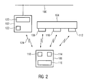
- FIG. 2 shows a block diagram of an HMI system comprising a technical equipment 104 with technical resources and an operating and monitoring device 106 with a transmitting and receiving module according to the invention.
- the technical equipment is eg part of a manufacturing or process engineering device.
- control automation components 102 are present, which intervene on the technical equipment, in particular by switching sensors, positioners and various other so-called "Process Instruments".
- the automation components 102 have, for example, an automation device, such as eg a programmable logic controller 120, which optionally effects the control of the technical equipment in real time.
- the automation components 102 are preferably connected to a bus system 100, e.g. a Profibus, affiliated. This enables universal networking of several automation components 102.
- At least one mobile operating and monitoring device 106 is present. This may e.g. be designed as a wireless hand-held terminal and e.g. have a display and a keyboard 116. Furthermore, emergency, release and acknowledgment keys and key switches can be provided.
- the mobile operating and monitoring device 106 exchanges payload data over a radio link 124 with the automation components 102 of the technical system 104 in a contactless manner.
- An operator using the HMI 106 may thus e.g. Display measured values of the technical system 104 on the display of the operating and monitoring device 106, or enter control commands via the keyboard 116 and send them to the automation components 102.
- the mobile operating device 106 and the automation components 102 For transmission of, for example, measured values and control commands between the mobile operating device 106 and the automation components 102, the mobile operating device 106 and the automation components 102 have corresponding data transmission modules 118, 122.
- This data transmission is preferably implemented by means of radio-frequency (RF) signals.
- RF radio-frequency
- a variety of different data transmission protocols can be used, such as WLAN, IEEE 802.11, Ultra Wide Band (UWB) or BlueTooth protocols.
- the mobile operating device 106 also has a localization module 114, which is designed for transmitting and receiving radar signals. Furthermore, the technical system 104 has at least one transponder. The system preferably has a series of transponders 108, 110, 112, which are attached to the technical system 104 at various reference points. The transponders are designed to modulate and reflect the radar signals emitted by the localization module 114. The radar signals modulated and reflected by the transponders 108, 110, 112 can then be received by the localization module 114 and evaluated for locating the mobile operator device 106. The mobile operating device 106 is thus able to perform a position or distance determination of the transponders 108, 110, 112 automatically. The transponders 108, 110, 112 do not have to carry out a signal evaluation.
- the localization module 114 is equipped with a transmission and reception module described above.
- the radar signals reflected by the transponders can be selectively evaluated.
- Subcarrier modulation thus allows separation of background signals and signals reflected at the transponders.
- a corresponding subcarrier filtering in the localization module 114 therefore, with the aid of the FMCW radar, which is only transmitted for a short time, a clear distance measurement for quasi-stationary destinations can be carried out even with a receiver of only one Real signal evaluation is designed to be implemented in the localization module 114.
- quasi-stationary means that the position of the transponder or the position of the radar system does not change during the measuring time, which is typically in the range of a few ms to a few tens of ms.
- FIG. 3 shows a flowchart of a preferred embodiment of a method according to the invention for distance measurement and data transmission in a continuous wave radar system, in which a transmitting and receiving module and at least one transponder device are arranged.
- a predetermined frequency range is sampled in order to examine this frequency range as to which frequency bands are still free and are not occupied by other devices or systems.
- an unmodulated continuous wave signal having a frequency which lies in a free frequency band is generated.
- a transponder device is searched for using the unmodulated continuous wave signal as a polling signal.
- transponder devices of the continuous wave radar system are set up in such a way that, in response to the interrogation signal, they send a radio answer signal to the transceiver module (step S4).
- step S5 the generation of the unmodulated continuous wave signal is stopped and instead a frequency-modulated continuous wave signal is generated (step S5).
- a distance between the transmitting and receiving module and the transponder device which transmits the radio answer signal is measured in a step S6.
- the unmodulated continuous-wave signal is generated again for a predetermined time, wherein this step can also take place immediately after step S4 (not shown). That is, the unmodulated continuous wave signal is generated again for a predetermined time after the transmitting and receiving module has received a radio answer signal from a transponder device.
Landscapes
- Engineering & Computer Science (AREA)
- Radar, Positioning & Navigation (AREA)
- Remote Sensing (AREA)
- Computer Networks & Wireless Communication (AREA)
- Physics & Mathematics (AREA)
- General Physics & Mathematics (AREA)
- Radar Systems Or Details Thereof (AREA)
Priority Applications (3)
| Application Number | Priority Date | Filing Date | Title |
|---|---|---|---|
| EP08010824A EP2133711B1 (fr) | 2008-06-13 | 2008-06-13 | Procédé de mesure de distance et transmission de données dans un système de radar à onde continue |
| US12/482,667 US8102303B2 (en) | 2008-06-13 | 2009-06-11 | Method for distance measurement and data transmission in a continuous wave radar system |
| CN200910149031.2A CN101604022B (zh) | 2008-06-13 | 2009-06-12 | 在连续波雷达系统中测距和传输数据的方法 |
Applications Claiming Priority (1)
| Application Number | Priority Date | Filing Date | Title |
|---|---|---|---|
| EP08010824A EP2133711B1 (fr) | 2008-06-13 | 2008-06-13 | Procédé de mesure de distance et transmission de données dans un système de radar à onde continue |
Publications (2)
| Publication Number | Publication Date |
|---|---|
| EP2133711A1 true EP2133711A1 (fr) | 2009-12-16 |
| EP2133711B1 EP2133711B1 (fr) | 2013-02-27 |
Family
ID=40091325
Family Applications (1)
| Application Number | Title | Priority Date | Filing Date |
|---|---|---|---|
| EP08010824A Ceased EP2133711B1 (fr) | 2008-06-13 | 2008-06-13 | Procédé de mesure de distance et transmission de données dans un système de radar à onde continue |
Country Status (3)
| Country | Link |
|---|---|
| US (1) | US8102303B2 (fr) |
| EP (1) | EP2133711B1 (fr) |
| CN (1) | CN101604022B (fr) |
Cited By (1)
| Publication number | Priority date | Publication date | Assignee | Title |
|---|---|---|---|---|
| DE102024102372A1 (de) * | 2024-01-29 | 2025-07-31 | Bayerische Motoren Werke Aktiengesellschaft | Verfahren zur Verbesserung einer Objekterkennung basierend auf einem Ultrabreitband-Sensor, Computerprogramm, Vorrichtung und Fahrzeug |
Families Citing this family (27)
| Publication number | Priority date | Publication date | Assignee | Title |
|---|---|---|---|---|
| CN102077115A (zh) * | 2008-07-02 | 2011-05-25 | Nxp股份有限公司 | 用于读取从应答器发送的信息的系统 |
| US8446253B2 (en) * | 2009-03-11 | 2013-05-21 | Checkpoint Systems, Inc. | Localization using virtual antenna arrays in modulated backscatter RFID systems |
| FI122310B (fi) | 2010-04-09 | 2011-11-30 | Teknologian Tutkimuskeskus Vtt | Menetelmä, järjestelmä ja tietokoneohjelmatuote RFID-tunnisteiden etäisyysmittaukseen |
| WO2012061765A1 (fr) * | 2010-11-05 | 2012-05-10 | Interdigital Patent Holdings, Inc. | Gestion de mesures de wtru pour limiter le brouillage intra-dispositif |
| CN102788974B (zh) * | 2011-05-17 | 2014-05-07 | 苏州市江海通讯发展实业有限公司 | 一种雷达应答器精确定位的方法 |
| CN102788971B (zh) * | 2011-05-17 | 2014-05-28 | 苏州市江海通讯发展实业有限公司 | 一种校准雷达应答器定位精度的方法 |
| CN103185882B (zh) * | 2011-12-29 | 2015-03-11 | 中国移动通信集团公司 | 一种相对位置测量方法、装置和系统 |
| DE102013213345A1 (de) * | 2013-07-08 | 2015-01-08 | Vega Grieshaber Kg | Universelle Messdatenerfassung in Gewässern |
| US9709672B2 (en) * | 2013-08-16 | 2017-07-18 | Drnc Holdings, Inc. | Method and system for identifying and finding a range of an object |
| US9702970B2 (en) * | 2013-08-30 | 2017-07-11 | Maxim Integrated Products, Inc. | Time of arrival delay cancellations |
| US9958533B2 (en) | 2013-09-06 | 2018-05-01 | Drnc Holdings, Inc. | Method and system for locating wireless devices within a local region |
| US9791550B2 (en) * | 2014-07-23 | 2017-10-17 | Honeywell International Inc. | Frequency-Modulated-Continuous-Wave (FMCW) radar with timing synchronization |
| KR20170060089A (ko) | 2014-09-22 | 2017-05-31 | 디알엔씨 홀딩스, 인크. | 델타-시그마 변조를 사용하는 무선 디바이스용 송신 장치 |
| US10067221B2 (en) * | 2015-04-06 | 2018-09-04 | Texas Instruments Incorporated | Interference detection in a frequency modulated continuous wave (FMCW) radar system |
| DE102015216220B4 (de) * | 2015-08-25 | 2018-05-03 | Continental Automotive Gmbh | Treiber für eine Kommunikation mit einem Transponder, insbesondere Treiber zum Einbau in ein Kraftfahrzeug und zur quasi-resonanten Kommunikation mit einem mobilen Transponder für ein Fahrzeugzugangs- und/oder Startsystem eines Kraftfahrzeugs |
| CN106162703B (zh) * | 2016-08-19 | 2019-04-16 | 张慧 | 一种用于测距测速的无线局域网通信系统 |
| LU100528B1 (en) * | 2017-12-01 | 2019-06-12 | Iee Sa | Radar System Operating Method and Radar System Having Improved Range Resolution by Mutually Delayed Orthogonal Codes |
| JP7194031B2 (ja) * | 2019-01-30 | 2022-12-21 | 古野電気株式会社 | レーダー装置 |
| US11204410B2 (en) * | 2019-02-11 | 2021-12-21 | Nxp B.V. | Radar-based communication |
| EP3969936B1 (fr) | 2019-07-09 | 2023-06-07 | Siemens Industry Software NV | Procédé de simulation de capteurs lidar à onde continue |
| US11550027B2 (en) | 2020-05-04 | 2023-01-10 | Nxp B.V. | Predistortion technique for joint radar/communication systems |
| US11946996B2 (en) * | 2020-06-30 | 2024-04-02 | Apple, Inc. | Ultra-accurate object tracking using radar in multi-object environment |
| CN112512177A (zh) * | 2020-11-06 | 2021-03-16 | 南京大学 | 一种连续波成像雷达的面阵光源驱动方法 |
| US12007465B2 (en) | 2021-10-19 | 2024-06-11 | Nxp B.V. | Radar apparatus and method with content embedded in the radar signal |
| CN114935754A (zh) * | 2022-07-20 | 2022-08-23 | 深圳芯盛思技术有限公司 | 采用数字调制技术的调频连续波雷达调制系统及使用方法 |
| CN116736280A (zh) * | 2023-07-03 | 2023-09-12 | 西安华镭电子技术部 | 电波测距仪 |
| CN119861363B (zh) * | 2025-01-14 | 2025-09-09 | 中国人民解放军63612部队 | 提升多频连续波雷达测量精度的方法 |
Citations (6)
| Publication number | Priority date | Publication date | Assignee | Title |
|---|---|---|---|---|
| US5712639A (en) * | 1995-09-19 | 1998-01-27 | Thomson-Csf | Method for the localizing of a transceiver of data packets |
| US5796362A (en) * | 1994-06-13 | 1998-08-18 | Hittite Microwave Corporation | Post launch on-board identification friend or foe system |
| US20030034887A1 (en) * | 2001-03-12 | 2003-02-20 | Crabtree Timothy L. | Article locator system |
| US6868073B1 (en) | 2000-06-06 | 2005-03-15 | Battelle Memorial Institute K1-53 | Distance/ranging by determination of RF phase delta |
| EP1760626A2 (fr) * | 2005-08-30 | 2007-03-07 | Fujitsu Ltd. | Interrogateur RFID et son procédé de communication des données |
| EP1903412A1 (fr) | 2006-09-22 | 2008-03-26 | Siemens Aktiengesellschaft | Procédé destiné à autoriser l'utilisation de composants d'automatisation d'une installation technique à l'aide d'un appareil d'observation et de commande mobile |
Family Cites Families (10)
| Publication number | Priority date | Publication date | Assignee | Title |
|---|---|---|---|---|
| US2903691A (en) * | 1946-02-01 | 1959-09-08 | Rossi Bruno | Range tracking circuit |
| US5153836A (en) * | 1990-08-22 | 1992-10-06 | Edward J. Fraughton | Universal dynamic navigation, surveillance, emergency location, and collision avoidance system and method |
| US6570913B1 (en) * | 1999-04-05 | 2003-05-27 | Cisco Technology, Inc. | Method and apparatus for selecting optimum frequency for upstream data transmission in a network system utilizing cable modems |
| DE10210037A1 (de) * | 2002-03-07 | 2003-10-02 | Siemens Ag | Aktiver Backscatter-Transponder, Kommunikationssystem mit einem solchen und Verfahren zum Übertragen von Daten mit einem solchen aktiven Backscatter-Transponder |
| US6998557B2 (en) * | 2003-08-29 | 2006-02-14 | Premark Feg L.L.C. | Power driven food machine and related multi-action switch assembly |
| GB0325622D0 (en) * | 2003-11-03 | 2003-12-10 | Cambridge Consultants | System for determining positional information |
| US7030761B2 (en) * | 2004-03-16 | 2006-04-18 | Symbol Technologies | Multi-resolution object location system and method |
| US7479884B1 (en) * | 2004-08-31 | 2009-01-20 | Cedar Ridge Research | System and method for monitoring objects, people, animals or places |
| JP2006108766A (ja) * | 2004-09-30 | 2006-04-20 | Fuji Xerox Co Ltd | 無線応答装置および画像形成装置 |
| EP1952662A4 (fr) * | 2005-11-24 | 2012-11-07 | Nokia Corp | Methodologie, module, terminal et systeme permettant un fonctionnement ordonnance d'un sous-systeme d'identification par radiofrequence (rfid) et sous-systeme de communication sans fil associe |
-
2008
- 2008-06-13 EP EP08010824A patent/EP2133711B1/fr not_active Ceased
-
2009
- 2009-06-11 US US12/482,667 patent/US8102303B2/en active Active
- 2009-06-12 CN CN200910149031.2A patent/CN101604022B/zh not_active Expired - Fee Related
Patent Citations (6)
| Publication number | Priority date | Publication date | Assignee | Title |
|---|---|---|---|---|
| US5796362A (en) * | 1994-06-13 | 1998-08-18 | Hittite Microwave Corporation | Post launch on-board identification friend or foe system |
| US5712639A (en) * | 1995-09-19 | 1998-01-27 | Thomson-Csf | Method for the localizing of a transceiver of data packets |
| US6868073B1 (en) | 2000-06-06 | 2005-03-15 | Battelle Memorial Institute K1-53 | Distance/ranging by determination of RF phase delta |
| US20030034887A1 (en) * | 2001-03-12 | 2003-02-20 | Crabtree Timothy L. | Article locator system |
| EP1760626A2 (fr) * | 2005-08-30 | 2007-03-07 | Fujitsu Ltd. | Interrogateur RFID et son procédé de communication des données |
| EP1903412A1 (fr) | 2006-09-22 | 2008-03-26 | Siemens Aktiengesellschaft | Procédé destiné à autoriser l'utilisation de composants d'automatisation d'une installation technique à l'aide d'un appareil d'observation et de commande mobile |
Non-Patent Citations (2)
| Title |
|---|
| KONNO K ET AL: "60 GHz Millimeter-Wave Dual Mode Radar for IVHS", TOPICAL SYMPOSIUM ON MILLIMETER WAVES, 1997, KANAGAWA, JAPAN, 7-8 JULY 1997, NEW YORK, NY, USA,IEEE, US, 7 July 1997 (1997-07-07), pages 159 - 161, XP010289054, ISBN: 978-0-7803-3887-6 * |
| KONNO K ET: "60 GHz Millimeter-Wave Dual Mode Radar for IVHS", TOPICAL SYMPOSIUM ON MILLIMETER WAVES, 7 July 1997 (1997-07-07), pages 159 - 161 |
Cited By (1)
| Publication number | Priority date | Publication date | Assignee | Title |
|---|---|---|---|---|
| DE102024102372A1 (de) * | 2024-01-29 | 2025-07-31 | Bayerische Motoren Werke Aktiengesellschaft | Verfahren zur Verbesserung einer Objekterkennung basierend auf einem Ultrabreitband-Sensor, Computerprogramm, Vorrichtung und Fahrzeug |
Also Published As
| Publication number | Publication date |
|---|---|
| CN101604022A (zh) | 2009-12-16 |
| US20090309780A1 (en) | 2009-12-17 |
| EP2133711B1 (fr) | 2013-02-27 |
| US8102303B2 (en) | 2012-01-24 |
| CN101604022B (zh) | 2015-11-25 |
Similar Documents
| Publication | Publication Date | Title |
|---|---|---|
| EP2133711B1 (fr) | Procédé de mesure de distance et transmission de données dans un système de radar à onde continue | |
| EP1903412B1 (fr) | Procédé destiné à autoriser l'utilisation de composants d'automatisation d'une installation technique à l'aide d'un appareil d'observation et de commande mobile | |
| EP3139139B1 (fr) | Appareil de mesure de niveau de remplissage avec mode de détection de signaux parasites | |
| DE112019001466T5 (de) | Entfernungsmesssystem | |
| EP3580731A1 (fr) | Procédé de fonctionnement d'un système d'authentification et système d'authentification | |
| DE102015118121A1 (de) | Mehrfach-sendeempfänger- und –antennenverifikationssystem | |
| EP0243885B1 (fr) | Procédé et dispositif d'établissement d'une communication dans un réseau radio à ondes courtes | |
| EP1672445B1 (fr) | Système d'interface homme-machine avec un dispositif d'operation et de surveillance pour des operations relatives à la sécurité d'une installation technique | |
| EP2850739B1 (fr) | Procédé de transmission radio par transmission ultra-large bande | |
| EP1672386B1 (fr) | Système radar à onde continue pour mesurer des distances et pour la transmission de données | |
| EP1681581B1 (fr) | Système de mesure de distance pour déterminer une zone de distances | |
| EP1681578A1 (fr) | Suppression du bruit pour un système radar | |
| EP1672387B1 (fr) | Système radar pour localiser un dispositif commande mobile | |
| EP1672385A1 (fr) | Usine de production et de traitement avec un dispositif transpondeur | |
| DE102022127451A1 (de) | Fahrzeuginternes ultrabreitband-system und -verfahren | |
| WO2023217424A1 (fr) | Dispositif de communication, procédé de communication, et programme informatique | |
| EP1655684B1 (fr) | Lecteur sans contact pour lire des données à partir d'un transpondeur | |
| DE102017118324B4 (de) | Anordnung und Verfahren zur Abstandsmessung zwischen Geräten in einem Funksystem | |
| EP1672380B1 (fr) | Système à interface homme-machine avec un concept d'émission et de réception integré | |
| EP2656528A1 (fr) | Procédé de fonctionnement d'un système de reconnaissance électronique dans un environnement protégé par un émetteur brouilleur | |
| DE102022111492A1 (de) | Verfahren sowie System zur Störung eines unbemannten Luftfahrzeugs | |
| EP2362553B1 (fr) | Procédé de détermination d'un canal d'émission pour un système RFID | |
| EP4645284A1 (fr) | Procédé de détection de drones, procédé d'apprentissage d'un modèle d'ia, programme informatique et appareil de détection pour exécuter le procédé de détection | |
| EP4636438A1 (fr) | Procédé de détection de drone et de détermination de la distance à sa télécommande, programme informatique et appareil de détection pour la mise en oeuvre du procédé | |
| DE102024003180A1 (de) | Verfahren zur Detektion von Drohnen, Verfahren zum Trainieren eines KI-Modells, Computerprogramm und Erfassungsgerät zur Durchführung des Detektionverfahrens |
Legal Events
| Date | Code | Title | Description |
|---|---|---|---|
| PUAI | Public reference made under article 153(3) epc to a published international application that has entered the european phase |
Free format text: ORIGINAL CODE: 0009012 |
|
| AK | Designated contracting states |
Kind code of ref document: A1 Designated state(s): AT BE BG CH CY CZ DE DK EE ES FI FR GB GR HR HU IE IS IT LI LT LU LV MC MT NL NO PL PT RO SE SI SK TR |
|
| AX | Request for extension of the european patent |
Extension state: AL BA MK RS |
|
| 17P | Request for examination filed |
Effective date: 20100607 |
|
| AKX | Designation fees paid |
Designated state(s): DE FR GB IT |
|
| 17Q | First examination report despatched |
Effective date: 20110216 |
|
| GRAP | Despatch of communication of intention to grant a patent |
Free format text: ORIGINAL CODE: EPIDOSNIGR1 |
|
| GRAS | Grant fee paid |
Free format text: ORIGINAL CODE: EPIDOSNIGR3 |
|
| GRAA | (expected) grant |
Free format text: ORIGINAL CODE: 0009210 |
|
| AK | Designated contracting states |
Kind code of ref document: B1 Designated state(s): DE FR GB IT |
|
| REG | Reference to a national code |
Ref country code: GB Ref legal event code: FG4D Free format text: NOT ENGLISH |
|
| RAP2 | Party data changed (patent owner data changed or rights of a patent transferred) |
Owner name: SIEMENS AKTIENGESELLSCHAFT |
|
| REG | Reference to a national code |
Ref country code: DE Ref legal event code: R096 Ref document number: 502008009306 Country of ref document: DE Effective date: 20130425 |
|
| PLBE | No opposition filed within time limit |
Free format text: ORIGINAL CODE: 0009261 |
|
| STAA | Information on the status of an ep patent application or granted ep patent |
Free format text: STATUS: NO OPPOSITION FILED WITHIN TIME LIMIT |
|
| 26N | No opposition filed |
Effective date: 20131128 |
|
| REG | Reference to a national code |
Ref country code: DE Ref legal event code: R097 Ref document number: 502008009306 Country of ref document: DE Effective date: 20131128 |
|
| PG25 | Lapsed in a contracting state [announced via postgrant information from national office to epo] |
Ref country code: IT Free format text: LAPSE BECAUSE OF NON-PAYMENT OF DUE FEES Effective date: 20130613 |
|
| REG | Reference to a national code |
Ref country code: FR Ref legal event code: PLFP Year of fee payment: 9 |
|
| REG | Reference to a national code |
Ref country code: FR Ref legal event code: PLFP Year of fee payment: 10 |
|
| REG | Reference to a national code |
Ref country code: FR Ref legal event code: PLFP Year of fee payment: 11 |
|
| PGFP | Annual fee paid to national office [announced via postgrant information from national office to epo] |
Ref country code: GB Payment date: 20220714 Year of fee payment: 15 |
|
| PGFP | Annual fee paid to national office [announced via postgrant information from national office to epo] |
Ref country code: FR Payment date: 20230619 Year of fee payment: 16 Ref country code: DE Payment date: 20220630 Year of fee payment: 16 |
|
| GBPC | Gb: european patent ceased through non-payment of renewal fee |
Effective date: 20230613 |
|
| PG25 | Lapsed in a contracting state [announced via postgrant information from national office to epo] |
Ref country code: GB Free format text: LAPSE BECAUSE OF NON-PAYMENT OF DUE FEES Effective date: 20230613 |
|
| REG | Reference to a national code |
Ref country code: DE Ref legal event code: R119 Ref document number: 502008009306 Country of ref document: DE |
|
| PG25 | Lapsed in a contracting state [announced via postgrant information from national office to epo] |
Ref country code: DE Free format text: LAPSE BECAUSE OF NON-PAYMENT OF DUE FEES Effective date: 20250101 |
|
| PG25 | Lapsed in a contracting state [announced via postgrant information from national office to epo] |
Ref country code: FR Free format text: LAPSE BECAUSE OF NON-PAYMENT OF DUE FEES Effective date: 20240630 |