EP2133768B1 - Encliquetages d'ajustement de précision pour hélicoptère - Google Patents
Encliquetages d'ajustement de précision pour hélicoptère Download PDFInfo
- Publication number
- EP2133768B1 EP2133768B1 EP09251109A EP09251109A EP2133768B1 EP 2133768 B1 EP2133768 B1 EP 2133768B1 EP 09251109 A EP09251109 A EP 09251109A EP 09251109 A EP09251109 A EP 09251109A EP 2133768 B1 EP2133768 B1 EP 2133768B1
- Authority
- EP
- European Patent Office
- Prior art keywords
- detent
- flight
- flight path
- control lever
- collective control
- Prior art date
- Legal status (The legal status is an assumption and is not a legal conclusion. Google has not performed a legal analysis and makes no representation as to the accuracy of the status listed.)
- Active
Links
Images







Classifications
-
- B—PERFORMING OPERATIONS; TRANSPORTING
- B64—AIRCRAFT; AVIATION; COSMONAUTICS
- B64C—AEROPLANES; HELICOPTERS
- B64C13/00—Control systems or transmitting systems for actuating flying-control surfaces, lift-increasing flaps, air brakes, or spoilers
- B64C13/24—Transmitting means
- B64C13/26—Transmitting means without power amplification or where power amplification is irrelevant
- B64C13/28—Transmitting means without power amplification or where power amplification is irrelevant mechanical
- B64C13/345—Transmitting means without power amplification or where power amplification is irrelevant mechanical with artificial feel
-
- B—PERFORMING OPERATIONS; TRANSPORTING
- B64—AIRCRAFT; AVIATION; COSMONAUTICS
- B64C—AEROPLANES; HELICOPTERS
- B64C27/00—Rotorcraft; Rotors peculiar thereto
- B64C27/54—Mechanisms for controlling blade adjustment or movement relative to rotor head, e.g. lag-lead movement
- B64C27/56—Mechanisms for controlling blade adjustment or movement relative to rotor head, e.g. lag-lead movement characterised by the control initiating means, e.g. manually actuated
-
- G—PHYSICS
- G05—CONTROLLING; REGULATING
- G05D—SYSTEMS FOR CONTROLLING OR REGULATING NON-ELECTRIC VARIABLES
- G05D1/00—Control of position, course, altitude or attitude of land, water, air or space vehicles, e.g. using automatic pilots
- G05D1/04—Control of altitude or depth
- G05D1/06—Rate of change of altitude or depth
- G05D1/0607—Rate of change of altitude or depth specially adapted for aircraft
-
- G—PHYSICS
- G05—CONTROLLING; REGULATING
- G05D—SYSTEMS FOR CONTROLLING OR REGULATING NON-ELECTRIC VARIABLES
- G05D1/00—Control of position, course, altitude or attitude of land, water, air or space vehicles, e.g. using automatic pilots
- G05D1/08—Control of attitude, i.e. control of roll, pitch, or yaw
- G05D1/0808—Control of attitude, i.e. control of roll, pitch, or yaw specially adapted for aircraft
- G05D1/0858—Control of attitude, i.e. control of roll, pitch, or yaw specially adapted for aircraft specially adapted for vertical take-off of aircraft
Definitions
- the present disclosure relates generally to aircraft and in particular to a method and apparatus for controlling the flight of aircraft. Still more particularly, the present disclosure relates to a method and apparatus for controlling the flight of a helicopter with a precision adjust split detent.
- An inceptor may be part of an active control system emulating mechanical components, such as springs and friction clutches actuated by an electric motor or other actuation device.
- the actuation device may be controlled by a controller to provide tactile cues to the vehicle operator.
- a tactile cue may be, for example, an amount of force applied to the inceptor, or an amount of resistance to movement of the inceptor.
- the tactile cues may provide a perception of a force or counter force on the inceptor being manipulated by an operator.
- the flight control computer In an example of an apparatus comprising an inceptor and a flight control computer, the flight control computer generates a first detent profile and a second detent profile in response to a set of parameters detected during flight, wherein the first detent profile includes an extension toward the second detent profile.
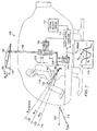
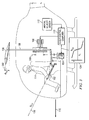
- flight control computer 110 may cause collective control lever 102 to move towards one of these detent positions.
- the detent position selected is the one that collective control lever 102 is closest to in this example. This type of movement occurs when pilot 114 relaxes or reduces force applied to collective control lever 102 .
- Force feel profile 124 also may be used to "backdrive" collective control lever 102 automatically when detent position 118 or detent position 122 are varied by flight control computer 110.
- These detent positions may be varied based on sensed velocities detected by inertial velocity sensor 112 . These changes are generated to hold a commanded flight path angle, such as that indicated by arrow 116 .
- the different advantageous embodiments allow pilot 114 to make fine adjustments to reduce a commanded flight path angle by a smaller amount than presently allowed with currently existing systems. These adjustments may be commands to change the flight path angle in the range of approximately 1.5 to approximately 4.5 degrees. This type of adjustment is important because small adjustments in flight path angle are necessary for precision landing approaches.
- the flight path adjustment may be, for example, the amount between arrow 116 and arrow 130 .
- force feel profile 124 may change various tactile cues, detent position 118 , and detent position 122 . These changes may be based on a set of parameters detected for helicopter 100 during flight.
- a set refers to one or more items.
- a set of parameters is one or more parameters.
- An example of a parameter may be, for example, without limitation, velocities detected by inertial velocity sensor 112 in these examples.
- detent position 118 may move towards detent position 120 , based on force feel profile 124 .
- Detent position 120 is a steady state position that is required to maintain level flight with neutral displacement of series actuator 106 .
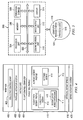
- tactile cues 406 may include a first detent and a second detent.
- a detent is a position for collective control lever 402 in which no force is needed by the operator to maintain collective control lever 402 in that position. Additionally, tactile cues 406 may push collective control lever 402 towards a detent position when the operator moves collective control lever 402 away from the detent position.
- the first detent may be flight path detent 412
- the second detent may be altitude detent 414 .
- Flight path detent 412 may be used to hold a flight path angle
- altitude detent 414 may be used to hold the altitude of an aircraft.
- Flight path detent 412 may be used to initiate or maintain the helicopter in a constant velocity state
- altitude detent 414 may be used in or used to initiate a constant altitude state of operation for the aircraft.
- flight path detent profile 411 includes detent latch force extension 416 .
- This component is an extension of flight path detent 412 towards altitude detent 414 .
- Detent latch force extension 416 makes it possible for a pilot or other operator of collective control lever 402 to move collective control lever 402 away from flight path detent 412 towards altitude detent 414 in a manner that requires the operator to exert force to move collective control lever 402 , but avoid unintended movements of collective control lever 402 from other factors.
- An unintended movement is any movement of collective control lever 402 that is not desired by the operator.
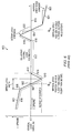
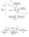
- detent latch width The distance between point 708 and point 712 is referred to as a detent latch width.
- the gradient present within this width is intended to hold the collective control lever position within a close tolerance of the flight path detent position identified by point 702 in these examples. This force is desired to hold the collective control lever close to point 702 even in the presence of gravity, friction, and/or an inadvertent application of force by the pilot to the collective control lever.
- the different advantageous embodiments increase the separation between point 902 and point 904 as shown with section 910 .
- This separation may be included in climbing or descending flight path angles or may be commanded to avoid interference between the force feel characteristics in line 906 and the force feel characteristics in line 908 .
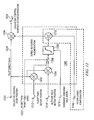
- flight path detent position 1212 altitude hold detent position 1214 , command deadzone half-width 1216 , and detent spread compensation 1218 are examples of aircraft sensor information, such as aircraft sensor information 1110 in Figure 11 .
- the command deadzone half-width is one half of the width of the entire command deadzone. For example, if a command deadzone is provided between collective control lever positions of 48 percent and 52 percent, the width of the deadzone would be 4 percent and the command deadzone half-width would be 2 percent.
- a command deadzone may be referred to as being +/- the command deadzone half-width. For example, +/- 2 percent for a deadzone that extends between control positions of 48 percent and 52 percent.
- the altitude hold detent cue indicates the point at which the pilot should stop moving the collective control lever so that the lever is positioned at the correct position to maintain level flight.
- the pilot may stop moving the collective control lever at a position that is somewhat higher than the natural unaugmented stick position required to hold altitude.
- the output of subtractor 1210 cancels the effect of initially positioning the collective control lever above the unaugmented position for altitude hold when level flight is captured from an initial commanded descent. In this manner, the control surface is commanded to collective control surface actuator position 1228 to provide for level flight capture without a transient overshoot.
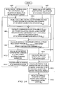
- FIG. 14 a flowchart of a process for generating a series actuator position and a force exerted on a collective lever is depicted in accordance with an advantageous embodiment.
- the process is an example of a process that may be implemented in a data processing system, such as data processing system 500 in Figure 5 .
- Many of the different operations illustrated in Figure 14 may operate concurrently even though the description of the different operations may be sequential.
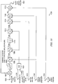
- commanded flight path angle ( ⁇ COM ) is calculated and the collective control lever position required to hold commanded flight path angle with neutral displacement of the series augmentation actuator (flight path detent position (8 C ⁇ )) is predicted (operation 1406 ).
- the commanded flight path angle ( ⁇ COM ) 618 and the flight path detent position are calculated using the calculations described in logic 1000 in Figure 10 .
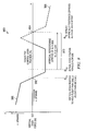
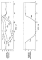
- the pilot may relax the stick force and allow the collective control lever to be pulled up into the flight path angle hold detent as illustrated in trace 1502 . From this point, the commanded flight path angle illustrated in trace 1600 may be held by the system as long as the pilot does not apply a force that exceeds a breakout limit for the flight path hold detent.
- trace 1900 represents the commanded flight path angle.
- the Y axis represents degrees
- the X axis represents time.
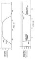
- trace 2000 represents the detent spread compensation command
- trace 2002 represents the detent augmentation command.
- the Y axis represents the percent of travel or position of the collective control lever while the X axis represents time.
- flight path angle 1900 When the desired commanded flight path angle, flight path angle 1900 , is reached at a time around point 1808 in Figure 18 , the pilot, in this example, relaxes the stick force and allows the collective control lever in trace 1800 to be pulled down into flight path angle hold detent 1802 . From this point, the command of flight path angle illustrated in trace 1900 may be held by the system as long as the pilot does not apply a stick force that exceeds the breakout limit of the flight path hold detent.
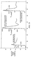
- the pilot can make a simple collective control lever input without encountering any overshoot of the desired rate of climb. As can be seen in trace 2204 a reduction in the rate of descent occurs without overshoot. This type of result occurs from implementation of one or more of the different advantageous embodiments.
- These embodiments include a detent latch force extension as illustrated in force feel profile 700 in Figure 7 .
- the different embodiments can take the form of a computer program product accessible from a computer-usable or computer-readable medium providing program code for use by or in connection with a computer or any device or system that executes instructions.
- a computer-usable or computer readable medium can generally be any tangible apparatus that can contain, store, communicate, propagate, or transport the program for use by or in connection with the instruction execution system, apparatus, or device.
Landscapes
- Engineering & Computer Science (AREA)
- Aviation & Aerospace Engineering (AREA)
- Automation & Control Theory (AREA)
- Radar, Positioning & Navigation (AREA)
- Remote Sensing (AREA)
- Physics & Mathematics (AREA)
- General Physics & Mathematics (AREA)
- Mechanical Engineering (AREA)
- Mechanical Control Devices (AREA)
- Control Of Position, Course, Altitude, Or Attitude Of Moving Bodies (AREA)
Claims (5)
- Système de commande de repérage tactile de positionneur divisé, comprenant:un initiateur (102, 400, 402) apte à être amené dans une pluralité de positions (118, 120, 122), où l'initiateur (102, 400, 402) est pour un hélicoptère (100);un capteur de position couplé à l'initiateur (102, 400, 402), où le capteur de position est apte à produire un signal de position;un ensemble de capteurs d'hélicoptère (112) apte à produire un ensemble de signaux en réponse à la détection d'un ensemble de paramètres se rapportant à l'hélicoptère (100) durant un vol; etun ordinateur de commande de vol (110, 404) couplé à l'initiateur (102, 400, 402) et à l'ensemble de capteurs d'hélicoptère (112), où l'ordinateur de commande de vol (110, 404) est configuré pour produire un premier ensemble de signaux d'actionnement utilisé pour produire un repérage tactile (406) pour produire un positionnement de maintien de chemin de vol (118, 412) dans la pluralité de positions (118, 120, 122), caractérisé en ce que le premier ensemble de signaux d'actionnement sont utilisés en outre pour produire un repérage tactile afin de produire un positionnement de maintien d'altitude (122, 414) dans la pluralité de positions (118, 120, 122), le positionnement de maintien de chemin de vol (118, 412) et le positionnement de maintien d'altitude (122, 414) étant produits en utilisant un profil de sensation de force (124, 417, 100) et l'ensemble de paramètres, où une extension (416, 716) d'une force de verrouillage du positionnement de maintien de chemin de vol (118, 412) au positionnement de maintien d'altitude (122, 414) est présente durant des changements de vitesse dans une direction de l'hélicoptère (100).
- Système de commande de repérage tactile de positionneur divisé selon la revendication 1, où l'ordinateur de commande de vol (110, 404) produit un deuxième ensemble de signaux d'actionnement utilisés pour produire des repérages tactiles (406) pour empêcher un chevauchement entre un profil de positionnement de maintien de chemin de vol (118, 412) et un profil de positionnement de maintien d'altitude (122, 414) lorsque des angles de trajectoire (116) dans une plage d'approximativement 1,5 à approximativement 4,5 degrés sont commandés.
- Système de commande de repérage tactile de positionneur divisé selon la revendication 1, où l'ordinateur de commande de vol (110, 404) produit un deuxième ensemble de signaux d'actionnement pour empêcher le chevauchement entre le profil de positionnement de maintien de trajectoire (118, 412) et le profil de positionnement de maintien d'altitude (122, 414), et l'actionneur série (106, 420) entre pour empêcher un dépassement d'un état de maintien d'altitude.
- Système de commande de repérage tactile de positionneur divisé selon la revendication 1, où le premier ensemble de signaux d'actionnement est transmis à un actionneur parallèle (104, 408) couplant l'ordinateur de commande de vol (110, 404) à l'intiateur (102, 400, 402).
- Système de commande de repérage tactile de positionneur divisé selon la revendication 1, où le deuxième ensemble de signaux d'actionnement est transmis à un actionneur parallèle (104, 408) couplant l'ordinateur de commande de vol (110, 410) à l'initiateur (102, 400, 402).
Applications Claiming Priority (1)
| Application Number | Priority Date | Filing Date | Title |
|---|---|---|---|
| US12/109,696 US8025256B2 (en) | 2008-04-25 | 2008-04-25 | Precision adjust split detent for a vehicle |
Publications (3)
| Publication Number | Publication Date |
|---|---|
| EP2133768A2 EP2133768A2 (fr) | 2009-12-16 |
| EP2133768A3 EP2133768A3 (fr) | 2010-09-29 |
| EP2133768B1 true EP2133768B1 (fr) | 2012-04-11 |
Family
ID=41110500
Family Applications (1)
| Application Number | Title | Priority Date | Filing Date |
|---|---|---|---|
| EP09251109A Active EP2133768B1 (fr) | 2008-04-25 | 2009-04-16 | Encliquetages d'ajustement de précision pour hélicoptère |
Country Status (3)
| Country | Link |
|---|---|
| US (1) | US8025256B2 (fr) |
| EP (1) | EP2133768B1 (fr) |
| AT (1) | ATE553425T1 (fr) |
Families Citing this family (35)
| Publication number | Priority date | Publication date | Assignee | Title |
|---|---|---|---|---|
| US9156546B2 (en) * | 2008-03-11 | 2015-10-13 | The Boeing Company | Active-inceptor tactile-cueing hands-off rate-limit |
| US9381998B2 (en) | 2009-10-19 | 2016-07-05 | Bae Systems Plc | Tactile cueing apparatus |
| CA2824932C (fr) * | 2011-01-14 | 2016-03-22 | Bell Helicopter Textron Inc. | Lois de commande de vol pour commande de trajectoire de vol vertical |
| US9162752B2 (en) | 2011-07-15 | 2015-10-20 | Bell Helicopter Textron Inc. | Flight control laws for automatic hover hold |
| US9102400B2 (en) * | 2011-10-21 | 2015-08-11 | Sikorsky Aircraft Corporation | Methods and systems for providing constant-feel, multi-axis tactile cues |
| US8967552B2 (en) * | 2012-10-19 | 2015-03-03 | Bell Helicopter Textron Inc. | Direct-drive control of aircraft stability augmentation |
| ES2739392T3 (es) * | 2012-12-20 | 2020-01-30 | Bae Systems Plc | Aparato inceptor |
| US9856017B2 (en) * | 2013-06-11 | 2018-01-02 | Bell Helicopter Textron Inc. | Torque based method of limiting vertical axis augmentation |
| CN103600836B (zh) * | 2013-11-08 | 2015-08-05 | 中航飞机股份有限公司西安飞机分公司 | 一种飞机突风锁防误操作结构 |
| US9121487B2 (en) * | 2013-11-13 | 2015-09-01 | Honeywell International Inc. | Pilot interface for aircraft electric taxi system |
| FR3016488B1 (fr) * | 2014-01-14 | 2016-02-12 | Ratier Figeac Soc | Procede et dispositif de commande d'un levier de manœuvre d'un vehicule |
| WO2015122876A1 (fr) * | 2014-02-11 | 2015-08-20 | Sikorsky Aircraft Corporation | Cran positif magnétique pour entrée de pilote hélicoptère |
| US9734726B2 (en) | 2014-02-17 | 2017-08-15 | The Boeing Company | Systems and methods for providing landing exceedance warnings and avoidance |
| US20150307203A1 (en) * | 2014-04-23 | 2015-10-29 | Sikorsky Aircraft Corporation | Vertical axis soft landing control |
| US9868522B2 (en) * | 2014-08-21 | 2018-01-16 | Bell Helicopter Textron Inc. | Rotorcraft autopilot control |
| EP3186147A4 (fr) | 2014-08-28 | 2018-04-25 | Sikorsky Aircraft Corporation | Système de commande de pas |
| US10676185B2 (en) * | 2014-08-28 | 2020-06-09 | Sikorsky Aircraft Corporation | Rotary wing aircraft pitch control system |
| US9437056B2 (en) | 2014-10-09 | 2016-09-06 | The Boeing Company | Methods and apparatus for operating flight control systems of aircrafts |
| PL3069990T3 (pl) * | 2015-03-20 | 2017-06-30 | Airbus Helicopters Deutschland GmbH | Urządzenie generujące sztuczne odczucie siły, do systemu sterowania pojazdu, a zwłaszcza statku powietrznego |
| FR3034750B1 (fr) * | 2015-04-13 | 2017-12-08 | Airbus Helicopters | Systeme de commande d'un rotor de giravion, giravion equipe d'un tel systeme et methode de commande associee |
| FR3042885B1 (fr) | 2015-10-23 | 2018-07-27 | Airbus Helicopters | Systeme de commande d'un rotor de giravion, giravion equipe d'un tel systeme et methide de commande associee |
| RU2624760C1 (ru) * | 2016-03-03 | 2017-07-06 | Сергей Николаевич Низов | Летательный аппарат |
| US10359785B2 (en) * | 2016-03-31 | 2019-07-23 | Sikorsky Aircraft Corporation | Touchdown orientation control system for a rotary wing aircraft and method |
| US10802482B2 (en) * | 2017-02-27 | 2020-10-13 | Textron Innovations Inc. | Reverse tactile cue for rotorcraft rotor overspeed protection |
| US10261517B2 (en) * | 2017-04-11 | 2019-04-16 | Bell Helicopter Textron Inc. | Default in-detent vertical speed/altitude hold |
| US10474237B2 (en) * | 2017-07-25 | 2019-11-12 | Rolls-Royce Corporation | Haptic feedback for rotary wing aircraft |
| US10926871B2 (en) * | 2017-11-27 | 2021-02-23 | Textron Innovations Inc. | System and method for pilot-in-control sensing in a rotorcraft |
| US11117653B2 (en) * | 2017-11-28 | 2021-09-14 | Textron Innovations Inc. | System and method for tactile cueing through rotorcraft pilot controls using variable friction and force gradient |
| US11059568B2 (en) | 2019-03-11 | 2021-07-13 | The Boeing Company | Variable operator interface for backdriving control input devices |
| US10908560B2 (en) * | 2019-03-11 | 2021-02-02 | The Boeing Company | Variable rate damping based control system for backdriven control input devices |
| CA3104051A1 (fr) * | 2019-12-30 | 2021-06-30 | Bombardier Inc. | Systemes et methodes pour controler une force resistive d`un incepteur d`un aeronef |
| US11623740B2 (en) | 2021-02-19 | 2023-04-11 | The Boeing Company | Split-reference system and method for rapid re-trimming rate command of force trim release |
| WO2023122111A1 (fr) * | 2021-12-23 | 2023-06-29 | Electra Aero, Inc. | Système et procédé de commande de trajectoire de vol d'un aéronef à portance soufflée |
| US12384550B2 (en) | 2021-12-23 | 2025-08-12 | Electra Aero, Inc. | System and method for controlling flight path of a blown lift aircraft |
| US12312067B2 (en) | 2022-01-24 | 2025-05-27 | Lockheed Martin Corporation | Deadband control for an aircraft |
Family Cites Families (4)
| Publication number | Priority date | Publication date | Assignee | Title |
|---|---|---|---|---|
| US5853152A (en) * | 1997-04-29 | 1998-12-29 | Sikorsky Aircraft Corporation | Collective detent system for vertical takeoff flight operations |
| EP1485892B1 (fr) * | 2002-03-21 | 2012-10-17 | Bell Helicopter Textron Inc. | Procede et appareil d'avertissement tactile sur les commandes d'aeronefs |
| US6679458B2 (en) * | 2002-06-10 | 2004-01-20 | The Boeing Company | Split detent tactile cueing vehicle control system |
| US7930074B2 (en) * | 2007-03-19 | 2011-04-19 | Sikorsky Aircraft Corporation | Vertical speed and flight path command module for displacement collective utilizing tactile cueing and tactile feedback |
-
2008
- 2008-04-25 US US12/109,696 patent/US8025256B2/en active Active
-
2009
- 2009-04-16 AT AT09251109T patent/ATE553425T1/de active
- 2009-04-16 EP EP09251109A patent/EP2133768B1/fr active Active
Also Published As
| Publication number | Publication date |
|---|---|
| US20090266940A1 (en) | 2009-10-29 |
| EP2133768A2 (fr) | 2009-12-16 |
| EP2133768A3 (fr) | 2010-09-29 |
| US8025256B2 (en) | 2011-09-27 |
| ATE553425T1 (de) | 2012-04-15 |
Similar Documents
| Publication | Publication Date | Title |
|---|---|---|
| EP2133768B1 (fr) | Encliquetages d'ajustement de précision pour hélicoptère | |
| CA2824932C (fr) | Lois de commande de vol pour commande de trajectoire de vol vertical | |
| US11561539B2 (en) | Aircraft control mode transition smoothing | |
| CN108536159B (zh) | 旋翼飞行器控制模式转换平滑 | |
| CN102712359B (zh) | 用于有人驾驶飞行器的控制系统的响应模式 | |
| EP2224306B1 (fr) | Compensation d'angle de tangage d'un pilote automatique | |
| US8442701B2 (en) | Dynamic roll angle stall protection for an aircraft | |
| US9472107B2 (en) | Method and device for determining a control set point of an aircraft, associated computer program and aircraft | |
| EP2787408B1 (fr) | Guidage d'approche finale | |
| EP0743243A1 (fr) | Système d'augmentation de la stabilité et de la manoeuvrabilité de l'axe de tangage pour aéronef | |
| KR101856122B1 (ko) | 회전익 항공기의 제어 시스템, 관련된 회전익 항공기 및 해당 제어 방법 | |
| EP3168143B1 (fr) | Procédé et appareil de protection de capacité de portance maximum d'aéronef | |
| US20130190949A1 (en) | Vehicle energy control system | |
| EP0384992B1 (fr) | Système de contrôle de la commande d'attitude en profondeur lors de l'arrondi à l'atterrissage | |
| EP3613671B1 (fr) | Lissage de transition de mode de commande de giravion | |
| CN103158882A (zh) | 带有单一界面的运输工具能量控制系统 | |
| EP3569497A1 (fr) | Système et procédé de repérage tactile grâce à des commandes pilotes de giravion utilisant un gradient de force et de friction variable | |
| EP2746887B1 (fr) | Amélioration et optimisation de la performance en approche rapide d'un aéronef | |
| EP2506108B1 (fr) | Système de compensation de trajectoire de vol vis à vis des variations de la vitesse par rapport à l'air | |
| CN111498095A (zh) | 用于控制旋翼飞行器的系统及方法 | |
| US12077282B2 (en) | Autonomous guidance and flight control system implementation on a partial-authority aircraft | |
| EP3575914A1 (fr) | Systeme et procede pour mode de vol automatique de descente en vol stationnaire | |
| US11130562B2 (en) | Reducing gust loads acting on an aircraft | |
| CN109144104B (zh) | 一种用于飞机复飞的方法和装置 |
Legal Events
| Date | Code | Title | Description |
|---|---|---|---|
| PUAI | Public reference made under article 153(3) epc to a published international application that has entered the european phase |
Free format text: ORIGINAL CODE: 0009012 |
|
| 17P | Request for examination filed |
Effective date: 20090511 |
|
| AK | Designated contracting states |
Kind code of ref document: A2 Designated state(s): AT BE BG CH CY CZ DE DK EE ES FI FR GB GR HR HU IE IS IT LI LT LU LV MC MK MT NL NO PL PT RO SE SI SK TR |
|
| RTI1 | Title (correction) |
Free format text: PRECISION ADJUST SPLIT DETENT FOR A HELICOPTER |
|
| PUAL | Search report despatched |
Free format text: ORIGINAL CODE: 0009013 |
|
| AK | Designated contracting states |
Kind code of ref document: A3 Designated state(s): AT BE BG CH CY CZ DE DK EE ES FI FR GB GR HR HU IE IS IT LI LT LU LV MC MK MT NL NO PL PT RO SE SI SK TR |
|
| AX | Request for extension of the european patent |
Extension state: AL BA RS |
|
| RTI1 | Title (correction) |
Free format text: PRECISION ADJUST SPLIT DETENT FOR A HELICOPTER |
|
| 17Q | First examination report despatched |
Effective date: 20110421 |
|
| RIC1 | Information provided on ipc code assigned before grant |
Ipc: B64C 13/14 20060101ALI20110706BHEP Ipc: G05D 1/08 20060101AFI20110706BHEP Ipc: B64C 27/56 20060101ALI20110706BHEP |
|
| GRAP | Despatch of communication of intention to grant a patent |
Free format text: ORIGINAL CODE: EPIDOSNIGR1 |
|
| GRAS | Grant fee paid |
Free format text: ORIGINAL CODE: EPIDOSNIGR3 |
|
| GRAA | (expected) grant |
Free format text: ORIGINAL CODE: 0009210 |
|
| AK | Designated contracting states |
Kind code of ref document: B1 Designated state(s): AT BE BG CH CY CZ DE DK EE ES FI FR GB GR HR HU IE IS IT LI LT LU LV MC MK MT NL NO PL PT RO SE SI SK TR |
|
| REG | Reference to a national code |
Ref country code: GB Ref legal event code: FG4D |
|
| REG | Reference to a national code |
Ref country code: CH Ref legal event code: EP |
|
| REG | Reference to a national code |
Ref country code: AT Ref legal event code: REF Ref document number: 553425 Country of ref document: AT Kind code of ref document: T Effective date: 20120415 |
|
| REG | Reference to a national code |
Ref country code: IE Ref legal event code: FG4D |
|
| REG | Reference to a national code |
Ref country code: DE Ref legal event code: R096 Ref document number: 602009006295 Country of ref document: DE Effective date: 20120606 |
|
| REG | Reference to a national code |
Ref country code: NL Ref legal event code: VDEP Effective date: 20120411 |
|
| REG | Reference to a national code |
Ref country code: AT Ref legal event code: MK05 Ref document number: 553425 Country of ref document: AT Kind code of ref document: T Effective date: 20120411 |
|
| LTIE | Lt: invalidation of european patent or patent extension |
Effective date: 20120411 |
|
| PG25 | Lapsed in a contracting state [announced via postgrant information from national office to epo] |
Ref country code: PL Free format text: LAPSE BECAUSE OF FAILURE TO SUBMIT A TRANSLATION OF THE DESCRIPTION OR TO PAY THE FEE WITHIN THE PRESCRIBED TIME-LIMIT Effective date: 20120411 Ref country code: SE Free format text: LAPSE BECAUSE OF FAILURE TO SUBMIT A TRANSLATION OF THE DESCRIPTION OR TO PAY THE FEE WITHIN THE PRESCRIBED TIME-LIMIT Effective date: 20120411 Ref country code: FI Free format text: LAPSE BECAUSE OF FAILURE TO SUBMIT A TRANSLATION OF THE DESCRIPTION OR TO PAY THE FEE WITHIN THE PRESCRIBED TIME-LIMIT Effective date: 20120411 Ref country code: NO Free format text: LAPSE BECAUSE OF FAILURE TO SUBMIT A TRANSLATION OF THE DESCRIPTION OR TO PAY THE FEE WITHIN THE PRESCRIBED TIME-LIMIT Effective date: 20120711 Ref country code: IS Free format text: LAPSE BECAUSE OF FAILURE TO SUBMIT A TRANSLATION OF THE DESCRIPTION OR TO PAY THE FEE WITHIN THE PRESCRIBED TIME-LIMIT Effective date: 20120811 Ref country code: CY Free format text: LAPSE BECAUSE OF FAILURE TO SUBMIT A TRANSLATION OF THE DESCRIPTION OR TO PAY THE FEE WITHIN THE PRESCRIBED TIME-LIMIT Effective date: 20120411 Ref country code: LT Free format text: LAPSE BECAUSE OF FAILURE TO SUBMIT A TRANSLATION OF THE DESCRIPTION OR TO PAY THE FEE WITHIN THE PRESCRIBED TIME-LIMIT Effective date: 20120411 |
|
| PG25 | Lapsed in a contracting state [announced via postgrant information from national office to epo] |
Ref country code: PT Free format text: LAPSE BECAUSE OF FAILURE TO SUBMIT A TRANSLATION OF THE DESCRIPTION OR TO PAY THE FEE WITHIN THE PRESCRIBED TIME-LIMIT Effective date: 20120813 Ref country code: MC Free format text: LAPSE BECAUSE OF NON-PAYMENT OF DUE FEES Effective date: 20120430 Ref country code: LV Free format text: LAPSE BECAUSE OF FAILURE TO SUBMIT A TRANSLATION OF THE DESCRIPTION OR TO PAY THE FEE WITHIN THE PRESCRIBED TIME-LIMIT Effective date: 20120411 Ref country code: HR Free format text: LAPSE BECAUSE OF FAILURE TO SUBMIT A TRANSLATION OF THE DESCRIPTION OR TO PAY THE FEE WITHIN THE PRESCRIBED TIME-LIMIT Effective date: 20120411 Ref country code: SI Free format text: LAPSE BECAUSE OF FAILURE TO SUBMIT A TRANSLATION OF THE DESCRIPTION OR TO PAY THE FEE WITHIN THE PRESCRIBED TIME-LIMIT Effective date: 20120411 Ref country code: GR Free format text: LAPSE BECAUSE OF FAILURE TO SUBMIT A TRANSLATION OF THE DESCRIPTION OR TO PAY THE FEE WITHIN THE PRESCRIBED TIME-LIMIT Effective date: 20120712 |
|
| PG25 | Lapsed in a contracting state [announced via postgrant information from national office to epo] |
Ref country code: BE Free format text: LAPSE BECAUSE OF FAILURE TO SUBMIT A TRANSLATION OF THE DESCRIPTION OR TO PAY THE FEE WITHIN THE PRESCRIBED TIME-LIMIT Effective date: 20120411 |
|
| REG | Reference to a national code |
Ref country code: IE Ref legal event code: MM4A |
|
| PG25 | Lapsed in a contracting state [announced via postgrant information from national office to epo] |
Ref country code: CZ Free format text: LAPSE BECAUSE OF FAILURE TO SUBMIT A TRANSLATION OF THE DESCRIPTION OR TO PAY THE FEE WITHIN THE PRESCRIBED TIME-LIMIT Effective date: 20120411 Ref country code: NL Free format text: LAPSE BECAUSE OF FAILURE TO SUBMIT A TRANSLATION OF THE DESCRIPTION OR TO PAY THE FEE WITHIN THE PRESCRIBED TIME-LIMIT Effective date: 20120411 Ref country code: SK Free format text: LAPSE BECAUSE OF FAILURE TO SUBMIT A TRANSLATION OF THE DESCRIPTION OR TO PAY THE FEE WITHIN THE PRESCRIBED TIME-LIMIT Effective date: 20120411 Ref country code: IE Free format text: LAPSE BECAUSE OF NON-PAYMENT OF DUE FEES Effective date: 20120416 Ref country code: EE Free format text: LAPSE BECAUSE OF FAILURE TO SUBMIT A TRANSLATION OF THE DESCRIPTION OR TO PAY THE FEE WITHIN THE PRESCRIBED TIME-LIMIT Effective date: 20120411 Ref country code: RO Free format text: LAPSE BECAUSE OF FAILURE TO SUBMIT A TRANSLATION OF THE DESCRIPTION OR TO PAY THE FEE WITHIN THE PRESCRIBED TIME-LIMIT Effective date: 20120411 Ref country code: DK Free format text: LAPSE BECAUSE OF FAILURE TO SUBMIT A TRANSLATION OF THE DESCRIPTION OR TO PAY THE FEE WITHIN THE PRESCRIBED TIME-LIMIT Effective date: 20120411 Ref country code: AT Free format text: LAPSE BECAUSE OF FAILURE TO SUBMIT A TRANSLATION OF THE DESCRIPTION OR TO PAY THE FEE WITHIN THE PRESCRIBED TIME-LIMIT Effective date: 20120411 |
|
| PLBE | No opposition filed within time limit |
Free format text: ORIGINAL CODE: 0009261 |
|
| STAA | Information on the status of an ep patent application or granted ep patent |
Free format text: STATUS: NO OPPOSITION FILED WITHIN TIME LIMIT |
|
| PG25 | Lapsed in a contracting state [announced via postgrant information from national office to epo] |
Ref country code: MK Free format text: LAPSE BECAUSE OF FAILURE TO SUBMIT A TRANSLATION OF THE DESCRIPTION OR TO PAY THE FEE WITHIN THE PRESCRIBED TIME-LIMIT Effective date: 20120411 |
|
| 26N | No opposition filed |
Effective date: 20130114 |
|
| PG25 | Lapsed in a contracting state [announced via postgrant information from national office to epo] |
Ref country code: ES Free format text: LAPSE BECAUSE OF FAILURE TO SUBMIT A TRANSLATION OF THE DESCRIPTION OR TO PAY THE FEE WITHIN THE PRESCRIBED TIME-LIMIT Effective date: 20120722 |
|
| REG | Reference to a national code |
Ref country code: DE Ref legal event code: R097 Ref document number: 602009006295 Country of ref document: DE Effective date: 20130114 |
|
| PG25 | Lapsed in a contracting state [announced via postgrant information from national office to epo] |
Ref country code: BG Free format text: LAPSE BECAUSE OF FAILURE TO SUBMIT A TRANSLATION OF THE DESCRIPTION OR TO PAY THE FEE WITHIN THE PRESCRIBED TIME-LIMIT Effective date: 20120711 Ref country code: MT Free format text: LAPSE BECAUSE OF FAILURE TO SUBMIT A TRANSLATION OF THE DESCRIPTION OR TO PAY THE FEE WITHIN THE PRESCRIBED TIME-LIMIT Effective date: 20120411 |
|
| REG | Reference to a national code |
Ref country code: CH Ref legal event code: PL |
|
| PG25 | Lapsed in a contracting state [announced via postgrant information from national office to epo] |
Ref country code: LI Free format text: LAPSE BECAUSE OF NON-PAYMENT OF DUE FEES Effective date: 20130430 Ref country code: CH Free format text: LAPSE BECAUSE OF NON-PAYMENT OF DUE FEES Effective date: 20130430 |
|
| PG25 | Lapsed in a contracting state [announced via postgrant information from national office to epo] |
Ref country code: TR Free format text: LAPSE BECAUSE OF FAILURE TO SUBMIT A TRANSLATION OF THE DESCRIPTION OR TO PAY THE FEE WITHIN THE PRESCRIBED TIME-LIMIT Effective date: 20120411 |
|
| PG25 | Lapsed in a contracting state [announced via postgrant information from national office to epo] |
Ref country code: LU Free format text: LAPSE BECAUSE OF NON-PAYMENT OF DUE FEES Effective date: 20120416 |
|
| PG25 | Lapsed in a contracting state [announced via postgrant information from national office to epo] |
Ref country code: HU Free format text: LAPSE BECAUSE OF FAILURE TO SUBMIT A TRANSLATION OF THE DESCRIPTION OR TO PAY THE FEE WITHIN THE PRESCRIBED TIME-LIMIT Effective date: 20090416 |
|
| REG | Reference to a national code |
Ref country code: FR Ref legal event code: PLFP Year of fee payment: 8 |
|
| REG | Reference to a national code |
Ref country code: FR Ref legal event code: PLFP Year of fee payment: 9 |
|
| REG | Reference to a national code |
Ref country code: FR Ref legal event code: PLFP Year of fee payment: 10 |
|
| P01 | Opt-out of the competence of the unified patent court (upc) registered |
Effective date: 20230516 |
|
| REG | Reference to a national code |
Ref country code: DE Ref legal event code: R079 Ref document number: 602009006295 Country of ref document: DE Free format text: PREVIOUS MAIN CLASS: G05D0001080000 Ipc: G05D0001490000 |
|
| PGFP | Annual fee paid to national office [announced via postgrant information from national office to epo] |
Ref country code: DE Payment date: 20250429 Year of fee payment: 17 |
|
| PGFP | Annual fee paid to national office [announced via postgrant information from national office to epo] |
Ref country code: GB Payment date: 20250428 Year of fee payment: 17 |
|
| PGFP | Annual fee paid to national office [announced via postgrant information from national office to epo] |
Ref country code: IT Payment date: 20250422 Year of fee payment: 17 |
|
| PGFP | Annual fee paid to national office [announced via postgrant information from national office to epo] |
Ref country code: FR Payment date: 20250425 Year of fee payment: 17 |