EP2133770A2 - Carte mère dotée d'une région supplémentaire d'emplacement pour module régulateur de la tension et module électronique correspondant - Google Patents
Carte mère dotée d'une région supplémentaire d'emplacement pour module régulateur de la tension et module électronique correspondant Download PDFInfo
- Publication number
- EP2133770A2 EP2133770A2 EP08252928A EP08252928A EP2133770A2 EP 2133770 A2 EP2133770 A2 EP 2133770A2 EP 08252928 A EP08252928 A EP 08252928A EP 08252928 A EP08252928 A EP 08252928A EP 2133770 A2 EP2133770 A2 EP 2133770A2
- Authority
- EP
- European Patent Office
- Prior art keywords
- vrm
- cpu
- slot
- voltage regulator
- card
- Prior art date
- Legal status (The legal status is an assumption and is not a legal conclusion. Google has not performed a legal analysis and makes no representation as to the accuracy of the status listed.)
- Withdrawn
Links
Images

Classifications
-
- G—PHYSICS
- G06—COMPUTING OR CALCULATING; COUNTING
- G06F—ELECTRIC DIGITAL DATA PROCESSING
- G06F1/00—Details not covered by groups G06F3/00 - G06F13/00 and G06F21/00
- G06F1/26—Power supply means, e.g. regulation thereof
Definitions
- the present invention relates to a motherboard and an associated electronic module and more particularly to a motherboard with an additional voltage regulator module slot area and an associated electronic module.
- the central processing unit (CPU) inside the computer must have a strong computation power so as to handle complicated and varied scheduling of system tasks.
- the loading of the CPU for different task scheduling may also be different, so the power consumption of the CPU changes with the loading of the CPU, that is, the power consumption of the CPU increases or decreases in an instant following the currently-performed task scheduling is changed. Facing this situation, the common power supply in the computer cannot provide real-time change of the supplied power for the CPU.
- the motherboard usually disposes a power supply module specially designed for the CPU.
- This special power supply module composed of a pulse width modulation (PWM) driving circuit, MOS transistors, chokes, capacitors, etc., is called a voltage regulator module (VRM).
- PWM pulse width modulation
- VRM voltage regulator module
- the VRM can detect the voltage level request of the CPU by detecting a Voltage IDentificator (VID) signal issued by the CPU, search a predefined lookup table for the required voltage value corresponding to the VID signal, and then adjust the working voltage of the CPU. In this way, the normal operation of the CPU can be assured by avoiding the abrupt change of the voltage resulted from the sudden change of the current.
- the PWM driving circuit is used to convert the amplitude of an input voltage into a pulse signal, monitor the output status of the power circuit so as to make real-time correction, and control switches of the MOS transistors for current control.
- the chokes are used for power storage and rectification, that is, they temporarily store excess current when the current passes and release electric energy in the lack of current, thereby achieving the effect of current stabilization.
- the capacitors are used for power storage and filtering, that is, they can not only remove low frequency noises but also store the current so as to assure the stable power supply for the CPU.
- the motherboard supplies the CPU with proper powers by using the above VRM. Since the power consumption of the CPU is increasingly large in nowadays, the motherboard is usually disposed with a multi-phase VRM including multiple groups of transistors, chokes and capacitors which can averagely share a high current resulted from the high power consumption, thereby increasing the life span and security of the motherboard.
- This design of using the VRM with a high phase number can quickly react to an abrupt loading change of the CPU so as to effectively enhance the operation stability of the motherboard.
- the VRM on the motherboard is continuously developed from the initial 2-phase power supply to 12-phase power supply, with the phase number changing with the working power of the CPU.
- a 40W CPU needs a 2-phase or 3-phase VRM, while a 150W CPU needs a 6-phase VRM for performing the power control.
- their required working power varies with their property and market positioning. For example, if the CPU is positioned as low power consumption, then it may need just 40W for normal operation; but if the CPU is positioned as high performance, then its working power may increase to more than 150W for assurance of normal operation.
- the working power of a single CPU increases with the increase of the working frequency thereof. The most common case is that the user adjusts the single CPU to a higher working frequency, i.e. over clocking, so as to upgrade the CPU performance.
- the working power of the modern CPU varies in a rather large range.
- the modern motherboard is usually disposed with a VRM with a high phase number (e.g. 8-phase) such that the user can install various CPUs with various working powers or upgrade the performance by over clocking a single CPU.
- phase number e.g. 8-phase
- this approach brings more and more complicated circuit layouts of the motherboard, which accordingly increases the complexity and cost of the manufacturing process of the motherboard and at the same time largely increases the whole size of the motherboard since multiple groups of transistors, chokes and capacitors must be disposed on the motherboard.
- a motherboard with an additional voltage regulator module (VRM) slot comprises: a central processing unit (CPU) slot for installing a CPU; a voltage regulator module, electrically connected to the CPU slot, for supplying the CPU installed in the CPU slot with a first power; a VRM slot area for installing a VRM card; and a control unit, electrically connected to the VRM slot area and electrically connected to the CPU slot in parallel with the voltage regulator module, for electrically conducting the VRM slot area with the CPU slot when the VRM card is installed into the VRM slot area, so as to make the VRM card and the voltage regulator module together supply the CPU installed in the CPU slot with a second power, wherein the second power is greater than the first power.
- CPU central processing unit
- VRM slot area for installing a VRM card
- a control unit electrically connected to the VRM slot area and electrically connected to the CPU slot in parallel with the voltage regulator module, for electrically conducting the VRM slot area with the CPU slot when the VRM card is installed into the VRM slot area, so as to make
- the electronic module comprises: a central processing unit (CPU); a VRM card; and a motherboard, which comprises: a CPU slot for installing the CPU; a voltage regulator module, electrically connected to the CPU slot, for supplying the CPU with a first power; a VRM slot area for installing the VRM card; and a control unit, electrically connected to the VRM slot area and electrically connected to the CPU slot in parallel with the voltage regulator module, for electrically conducting the VRM slot area with the CPU slot when the VRM card is installed into the VRM slot area, so as to make the VRM card and the voltage regulator module together supply the CPU installed in the CPU slot with a second power, wherein the second power is greater than the first power.
- CPU central processing unit
- VRM card voltage regulator module
- a motherboard with an additional voltage regulator module (VRM) slot is also provided.
- the motherboard comprises: a central processing unit (CPU) slot for selectively installing a first CPU or a second CPU; a voltage regulator module, electrically connected to the CPU slot, for supplying a first power required for operation of the first CPU installed in the CPU slot; a VRM slot area for installing a VRM card; and a control unit, electrically connected to the VRM slot area and electrically connected to the CPU slot in parallel with the voltage regulator module, for electrically conducting the VRM slot area with the CPU slot when the VRM card is installed into the VRM slot area, so as to make the VRM card and the voltage regulator module together supply a second power required for operation of the second CPU installed in the CPU slot, wherein the second power is greater than the first power.
- CPU central processing unit
- VRM slot area for installing a VRM card
- a control unit electrically connected to the VRM slot area and electrically connected to the CPU slot in parallel with the voltage regulator module, for electrically conducting the VRM
- the electronic module comprises: a first central processing unit (CPU); a second CPU, wherein a second power required for operation of the second CPU is greater than a first power required for operation of the first CPU; a VRM card; and a motherboard, which comprises: a CPU slot for selectively installing the first CPU or the second CPU; a voltage regulator module, electrically connected to the CPU slot, for supplying the first CPU with a first power when the first CPU is installed in the CPU slot; a VRM slot area for installing the VRM card; and a control unit, electrically connected to the VRM slot area and electrically connected to the CPU slot in parallel with the voltage regulator module, for electrically conducting the VRM slot area with the CPU slot when the second CPU is installed in the CPU slot and the VRM card is installed into the VRM slot area, so as to make the VRM card and the voltage regulator module together supply the second CPU with the second power.
- CPU central processing unit
- VRM voltage regulator module
- Fig. 1 is a block diagram of an electronic module 10 according to the first embodiment of the present invention.
- the electronic module 10 includes a central processing unit (CPU) 12, a voltage regulator module (VRM) card 14 and a motherboard 16.
- the motherboard 16 includes a CPU slot 18, a VRM 20, a VRM slot area 22 and a control unit 24.
- the CPU 12 is installed into the CPU slot 18.
- the VRM 20 is used to supply a first power (e.g. 40W) required for the operation of the CPU 12.
- the VRM card 14 can be inserted into the VRM slot area 22, which is implemented as a single VRM slot or multiple VRM slots.
- the control unit 24 is electrically connected to the VRM slot area 22 and electrically connected to the CPU slot 18 in parallel with the VRM 20.
- the control unit 24 electrically conducts the VRM slot area 22 with the CPU slot 18 so as to make the VRM card 14 and the VRM 20 supply the CPU 12 with a second power (e.g. 140W) together.
- the second power is greater than the first power, and the first and second powers are not limited to the above values.
- the VRM card 14 can be a 4-phase VRM card, and the VRM 20 can be a 2-phase VRM.
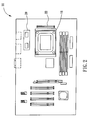
- Fig. 2 is a diagram showing the motherboard 16 in Fig. 1 .
- the VRM 20 When a user installs the CPU 12 into the CPU slot 18, the VRM 20 will detect a VID signal from the CPU 12, search the predefined lookup table for the required voltage value corresponding to the VID signal, and then start to supply the CPU 12 with the required power, such as 40W. Since the VRM card 14 is not installed in the VRM slot area 22 at this time, the control unit 24 controls the VRM slot area 22 not to connect with the CPU slot 18. Next, if the user wants to over clock the CPU 12 to enhance the CPU performance, the power required for the operation of the CPU 12 increases accordingly.
- the VRM 20 cannot supply the CPU 12 with the power required for over clocking (150W) when the VRM 20 is a 2-phase VRM which can supply just 40W.
- the user can insert the VRM card 14 into the VRM slot area 22.
- the control unit 24 first controls the VRM card 14 to have the same working voltage as the VRM 20, so as to prevent the reverse bias from influencing the operation of the VRM card 14 or the VRM 20. Then, the control unit 24 electrically conducts the VRM slot area 22 with the CPU slot 18, and thus the VRM card 14 (e.g.
- the 4-phase VRM card) and the VRM 20 can together supply the CPU 12 installed in the CPU slot 18 with the power required for over clocking (150W).
- the connection between the VRM card 14 and the VRM 20 can bring an effect equivalent to directly installing a 6-phase VRM onto the motherboard 16. That is, the combination of the VRM card 14 and the VRM 20 is substantially equivalent to the 6-phase VRM disposed on the motherboard 16.
- the power values required for the operation of the CPU 12 and the phase numbers of the VRM card 14 and the VRM 20 are not limited to those mentioned in the first embodiment.
- the VRM card 14 can also be a 6-phase VRM card, that is, the phase number of the VRM card 14 can be properly selected in accordance with actual situations.
- the circuit layout of the electronic module 10 is common technique in the prior arts. For instance, the circuit disposition of the VRM or the parallel disposition of the VRM and the CPU are well known to those skilled in the art, and will not be described in detail here.
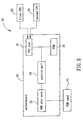
- Fig. 3 is a block diagram of an electronic module 50 according to the second embodiment of the present invention.
- the electronic module 50 includes a first CPU 52, a second CPU 54, the VRM card 14 and the motherboard 16.
- the power required for the operation of the second CPU 54 e.g. 150W
- the motherboard 16 includes the CPU slot 18, the VRM 20, the VRM slot area 22 and the control unit 24.
- the CPU slot 18 is used for selectively installing the first CPU 52 or the second CPU 54.
- the VRM 20 is electrically connected to the CPU slot 18 and used for supplying the power required for the operation of the first CPU 52.
- the VRM slot area 22 is used for installing the VRM card 14.
- the control unit 24 is electrically connected to the VRM slot area 22 and electrically connected to the CPU slot 18 in parallel with the voltage regulator module 20.
- the control unit 24 electrically conducts the VRM slot area 22 with the CPU slot 18 when the second CPU 54 is installed in the CPU slot 18 and the VRM card 14 is installed into the VRM slot area 22, so as to make the VRM card 14 and the VRM 20 together supply the power required for the operation of the second CPU 54.
- the VRM card 14 can be a 4-phase VRM card
- the VRM 20 can be a 2-phase VRM.
- the operation of the electronic module 50 is explained in detail as follows. Please refer to Fig. 2 and Fig. 3 .
- the VRM 20 When the user installs the first CPU 52 into the CPU slot 18, the VRM 20 will detect a VID signal from the first CPU 52, search the predefined lookup table for the required voltage value corresponding to the VID signal, and then start to supply the first CPU 52 with the required power, such as 40W. Since the VRM card 14 is not installed in the VRM slot area 22 at this time, the control unit 24 controls the VRM slot area 22 not to connect with the CPU slot 18.
- the VRM 20 cannot supply the required power (150W) for the second CPU 54 when the VRM 20 is a 2-phase VRM which can supply just 40W.
- the user can insert the VRM card 14 into the VRM slot area 22.
- the control unit 24 first controls the VRM card 14 to have the same working voltage as the VRM 20, so as to prevent the reverse bias from influencing the operation of the VRM card 14 or the VRM 20.
- the control unit 24 electrically conducts the VRM slot area 22 with the CPU slot 18, and thus the VRM card 14 (e.g. 4-phase VRM card) and the VRM 20 (e.g. 2-phase VRM) can together supply the second CPU 54 installed in the CPU slot 18 with the required power (150W). That is, even though the user replaces the first CPU 52 installed on the motherboard 16 with the second CPU 54, which requires a power exceeding that the VRM 20 can supply, the user can install the additional VRM card 14 into the VRM slot area 22 so as to make the second CPU 54 work normally.
- the power values required for the operation of the first CPU 52 and the second CPU 54 and the phase numbers of the VRM card 14 and the VRM 20 are not limited to those mentioned in the second embodiment.
- the VRM 20 can also be a 4-phase VRM, that is, the phase number of the VRM 20 can be properly selected in accordance with actual situations.
- the circuit layout of the electronic module 50 is also common technique in the prior arts. For instance, the circuit disposition of the VRM or the parallel disposition of the VRM and the CPU are well known to those skilled in the art, and will not be described in detail here.
- the present invention disposes an additional VRM slot area on the motherboard so as to reduce the motherboard space required for the disposition of the VRM circuit. That is, even if the motherboard is only disposed with a VRM having a low phase number, the user can still upgrade the CPU performance, with the help of an additional VRM card installed in the VRM slot of the motherboard, by over clocking the original CPU or installing another higher grade CPU. Since disposed with a VRM having a low phase number, the motherboard provided by the present invention can lower the complexity and cost of the manufacturing process of the motherboard, and greatly reduce the whole size of the motherboard at the same time.
Landscapes
- Engineering & Computer Science (AREA)
- Theoretical Computer Science (AREA)
- Physics & Mathematics (AREA)
- General Engineering & Computer Science (AREA)
- General Physics & Mathematics (AREA)
- Power Sources (AREA)
Applications Claiming Priority (1)
| Application Number | Priority Date | Filing Date | Title |
|---|---|---|---|
| TW097122172A TWI363959B (en) | 2008-06-13 | 2008-06-13 | Motherboard with an additional voltage regulator module slot area and related electronic module |
Publications (2)
| Publication Number | Publication Date |
|---|---|
| EP2133770A2 true EP2133770A2 (fr) | 2009-12-16 |
| EP2133770A3 EP2133770A3 (fr) | 2011-06-29 |
Family
ID=41009853
Family Applications (1)
| Application Number | Title | Priority Date | Filing Date |
|---|---|---|---|
| EP08252928A Withdrawn EP2133770A3 (fr) | 2008-06-13 | 2008-09-03 | Carte mère dotée d'une région supplémentaire d'emplacement pour module régulateur de la tension et module électronique correspondant |
Country Status (3)
| Country | Link |
|---|---|
| US (1) | US20090313485A1 (fr) |
| EP (1) | EP2133770A3 (fr) |
| TW (1) | TWI363959B (fr) |
Families Citing this family (13)
| Publication number | Priority date | Publication date | Assignee | Title |
|---|---|---|---|---|
| US8892911B2 (en) * | 2009-03-31 | 2014-11-18 | Lenovo (Singapore) Pte. Ltd. | Variable power systems for computers |
| US8463973B2 (en) * | 2010-08-31 | 2013-06-11 | Advanced Micro Devices, Inc. | Mechanism for voltage regulator load line compensation using multiple voltage settings per operating state |
| CN102520781A (zh) * | 2011-11-24 | 2012-06-27 | 浪潮电子信息产业股份有限公司 | 一种模块化的vrm设计方法 |
| US9545006B1 (en) | 2013-09-30 | 2017-01-10 | EMC IP Holding Company LLC | Configurable system board |
| US9801279B1 (en) * | 2013-09-30 | 2017-10-24 | EMC IP Holding Company LLC | Configurable system board |
| TWI571732B (zh) * | 2015-10-19 | 2017-02-21 | 技嘉科技股份有限公司 | 處理功能擴充卡及其電能擴充板 |
| CN106598144B (zh) * | 2015-10-19 | 2019-11-19 | 技嘉科技股份有限公司 | 处理功能扩充卡及其电能扩充板 |
| US10366734B2 (en) | 2017-02-03 | 2019-07-30 | Advanced Micro Devices, Inc. | Programmable write word line boost for low voltage memory operation |
| US11157274B2 (en) | 2019-11-26 | 2021-10-26 | International Business Machines Corporation | Architecture with micro-controller and high-speed active cables |
| US11177665B2 (en) | 2019-11-26 | 2021-11-16 | International Business Machines Corporation | Redundant voltage delivery with active cables |
| US12130715B2 (en) * | 2022-09-27 | 2024-10-29 | International Business Machines Corporation | Adaptive spare stages in configurable VRM card |
| CN115561512A (zh) * | 2022-09-27 | 2023-01-03 | 西安超越申泰信息科技有限公司 | 用于服务器的cpu假负载电路及cpu电流校验系统 |
| US12537046B2 (en) | 2023-06-29 | 2026-01-27 | Advanced Micro Devices, Inc. | RC-tuned wordline underdrive circuit |
Citations (5)
| Publication number | Priority date | Publication date | Assignee | Title |
|---|---|---|---|---|
| US5919259A (en) | 1997-04-18 | 1999-07-06 | Dahl; Nathaniel H. | Method and apparatus for supplying power to a CPU using an adaptor card |
| WO2002003532A2 (fr) | 2000-06-30 | 2002-01-10 | Intel Corporation | Systeme de regulation de tension a phases multiples |
| US6594556B1 (en) * | 1995-02-01 | 2003-07-15 | Intel Corporation | Upgradeable voltage regulator modules |
| US6694272B1 (en) * | 2001-11-08 | 2004-02-17 | Galaxy Power, Inc. | Microcontroller controlled voltage reference |
| US7301313B1 (en) | 1999-03-23 | 2007-11-27 | Intel Corporation | Multiple voltage regulators for use with a single load |
Family Cites Families (24)
| Publication number | Priority date | Publication date | Assignee | Title |
|---|---|---|---|---|
| US5629608A (en) * | 1994-12-28 | 1997-05-13 | Intel Corporation | Power regulation system for controlling voltage excursions |
| US5627413A (en) * | 1995-04-17 | 1997-05-06 | Intel Corporation | Voltage regulator disable circuit |
| US5694297A (en) * | 1995-09-05 | 1997-12-02 | Astec International Limited | Integrated circuit mounting structure including a switching power supply |
| US5787014A (en) * | 1996-03-29 | 1998-07-28 | Intel Corporation | Method and apparatus for automatically controlling integrated circuit supply voltages |
| KR100321976B1 (ko) * | 1997-12-29 | 2002-05-13 | 윤종용 | 인텔프로세서를위한오류허용전압조절모듈회로 |
| WO2000033153A1 (fr) * | 1998-12-03 | 2000-06-08 | Virginia Tech Intellectual Properties, Inc. | Modules regulateurs de tension (mrt) a detection de courant et partage du courant |
| US6449676B1 (en) * | 1999-03-30 | 2002-09-10 | International Business Machines Corporation | Hot-pluggable voltage regulator module |
| US6453421B1 (en) * | 1999-05-21 | 2002-09-17 | Intel Corporation | Processor system with power supply selection mechanism |
| US6865682B1 (en) * | 1999-06-18 | 2005-03-08 | Samsung Electronics Co., Ltd. | Microprocessor module with integrated voltage regulators |
| TW444170B (en) * | 1999-06-24 | 2001-07-01 | Via Tech Inc | Conversion card with dual-processor architecture |
| US6181556B1 (en) * | 1999-07-21 | 2001-01-30 | Richard K. Allman | Thermally-coupled heat dissipation apparatus for electronic devices |
| US6310792B1 (en) * | 1999-12-29 | 2001-10-30 | Intel Corporation | Shared package for VRM and processor unit |
| AU2001233095A1 (en) * | 2000-01-27 | 2001-08-07 | Primarion, Inc. | Apparatus for providing regulated power to an integrated circuit |
| US6366467B1 (en) * | 2000-03-31 | 2002-04-02 | Intel Corporation | Dual-socket interposer and method of fabrication therefor |
| US6262566B1 (en) * | 2000-06-15 | 2001-07-17 | Intel Corporation | DC-to-DC controller having a multi-phase synchronous buck regulator |
| US6784644B2 (en) * | 2001-02-22 | 2004-08-31 | Virginia Tech Intellectual Properties, Inc. | Multiphase clamp coupled-buck converter and magnetic integration |
| US6930889B2 (en) * | 2001-03-16 | 2005-08-16 | Intel Corporation | Circuit board and slot connector assembly |
| US6515460B1 (en) * | 2001-09-10 | 2003-02-04 | National Semiconductor Corporation | Multiphase switching regulator control architecture for low on time systems that enforces current sharing |
| US6837719B2 (en) * | 2002-02-25 | 2005-01-04 | Molex Incorporated | Connector with included filtered power delivery |
| US6845013B2 (en) * | 2002-03-04 | 2005-01-18 | Incep Technologies, Inc. | Right-angle power interconnect electronic packaging assembly |
| US7464280B2 (en) * | 2005-06-22 | 2008-12-09 | Hewlett-Packard Development Company, L.P. | Power module for a plurality of processors |
| TWI322346B (en) * | 2006-10-18 | 2010-03-21 | Asustek Comp Inc | Power supply system |
| US8498117B2 (en) * | 2006-11-16 | 2013-07-30 | Advanced Micro Devices, Inc. | Variable mount voltage regulator |
| US8018738B2 (en) * | 2008-06-02 | 2011-09-13 | Oracle America, Inc., | Voltage regulator attach for high current chip applications |
-
2008
- 2008-06-13 TW TW097122172A patent/TWI363959B/zh not_active IP Right Cessation
- 2008-09-03 EP EP08252928A patent/EP2133770A3/fr not_active Withdrawn
- 2008-09-29 US US12/286,208 patent/US20090313485A1/en not_active Abandoned
Patent Citations (5)
| Publication number | Priority date | Publication date | Assignee | Title |
|---|---|---|---|---|
| US6594556B1 (en) * | 1995-02-01 | 2003-07-15 | Intel Corporation | Upgradeable voltage regulator modules |
| US5919259A (en) | 1997-04-18 | 1999-07-06 | Dahl; Nathaniel H. | Method and apparatus for supplying power to a CPU using an adaptor card |
| US7301313B1 (en) | 1999-03-23 | 2007-11-27 | Intel Corporation | Multiple voltage regulators for use with a single load |
| WO2002003532A2 (fr) | 2000-06-30 | 2002-01-10 | Intel Corporation | Systeme de regulation de tension a phases multiples |
| US6694272B1 (en) * | 2001-11-08 | 2004-02-17 | Galaxy Power, Inc. | Microcontroller controlled voltage reference |
Also Published As
| Publication number | Publication date |
|---|---|
| EP2133770A3 (fr) | 2011-06-29 |
| US20090313485A1 (en) | 2009-12-17 |
| TW200951698A (en) | 2009-12-16 |
| TWI363959B (en) | 2012-05-11 |
Similar Documents
| Publication | Publication Date | Title |
|---|---|---|
| EP2133770A2 (fr) | Carte mère dotée d'une région supplémentaire d'emplacement pour module régulateur de la tension et module électronique correspondant | |
| US8726057B2 (en) | Power management of components having clock processing circuits | |
| JP5198475B2 (ja) | データ通信機能内蔵デバイス | |
| CN112701936A (zh) | 计算机电源供应组件及其制造方法 | |
| US8117466B2 (en) | Data processing device and power supply voltage generator that control a power supply voltage during an auxiliary period, and method of controlling the power supply voltage thereof during an auxiliary period | |
| US20090172427A1 (en) | Method and system for power management of a motherboard | |
| CN100504724C (zh) | 电源系统以及笔记本型个人计算机 | |
| US7203856B2 (en) | Mobile computer with desktop type processor | |
| US7293181B2 (en) | Use of one voltage regulator module to support two processors to improve power and thermal limitations | |
| CN103092304A (zh) | 双显卡模块的电源控制方法及应用该方法的电脑装置 | |
| CN101620461B (zh) | 具有附加电压调节模块插槽区的主机板及其相关电子模块 | |
| US7421593B2 (en) | Parallel-connected voltage regulators for supplying power to integrated circuit so that second regulator minimizes current output from first regulator | |
| US11256275B2 (en) | Power supply adjusting system, method and apparatus, chip, and electronic device | |
| WO2024104132A1 (fr) | Dispositif d'alimentation électrique, dispositif de réception d'énergie, puce et système d'alimentation électrique | |
| EP2105821A1 (fr) | Procédé de gestion de la puissance et système pour carte mère | |
| JP3254773U (ja) | 電力変換カード | |
| JP4649490B2 (ja) | メインボード用電力管理方法及びシステム | |
| CN222690139U (zh) | 接口电源控制电路、计算机主板及计算机 | |
| US8129941B2 (en) | Power supply with regulation of voltage boosting time | |
| US9690351B2 (en) | Power control system and method thereof | |
| US20130073881A1 (en) | Extensible external power supply | |
| JP2006014472A (ja) | Dc/dcコンバータを備える電子機器 | |
| CN117826949A (zh) | 一种计算设备的主板、计算设备及控制方法 | |
| CN112684874A (zh) | 一种多电源供电的装置及方法 | |
| US20130106387A1 (en) | Power supply |
Legal Events
| Date | Code | Title | Description |
|---|---|---|---|
| PUAI | Public reference made under article 153(3) epc to a published international application that has entered the european phase |
Free format text: ORIGINAL CODE: 0009012 |
|
| 17P | Request for examination filed |
Effective date: 20080910 |
|
| AK | Designated contracting states |
Kind code of ref document: A2 Designated state(s): AT BE BG CH CY CZ DE DK EE ES FI FR GB GR HR HU IE IS IT LI LT LU LV MC MT NL NO PL PT RO SE SI SK TR |
|
| AX | Request for extension of the european patent |
Extension state: AL BA MK RS |
|
| PUAL | Search report despatched |
Free format text: ORIGINAL CODE: 0009013 |
|
| AK | Designated contracting states |
Kind code of ref document: A3 Designated state(s): AT BE BG CH CY CZ DE DK EE ES FI FR GB GR HR HU IE IS IT LI LT LU LV MC MT NL NO PL PT RO SE SI SK TR |
|
| AX | Request for extension of the european patent |
Extension state: AL BA MK RS |
|
| 17Q | First examination report despatched |
Effective date: 20120203 |
|
| AKX | Designation fees paid |
Designated state(s): AT BE BG CH CY CZ DE DK EE ES FI FR GB GR HR HU IE IS IT LI LT LU LV MC MT NL NO PL PT RO SE SI SK TR |
|
| STAA | Information on the status of an ep patent application or granted ep patent |
Free format text: STATUS: THE APPLICATION HAS BEEN WITHDRAWN |
|
| 18W | Application withdrawn |
Effective date: 20150603 |