EP2134009A2 - Interféromètre à retard - Google Patents
Interféromètre à retard Download PDFInfo
- Publication number
- EP2134009A2 EP2134009A2 EP09161987A EP09161987A EP2134009A2 EP 2134009 A2 EP2134009 A2 EP 2134009A2 EP 09161987 A EP09161987 A EP 09161987A EP 09161987 A EP09161987 A EP 09161987A EP 2134009 A2 EP2134009 A2 EP 2134009A2
- Authority
- EP
- European Patent Office
- Prior art keywords
- light
- delay interferometer
- axis
- output
- channel
- Prior art date
- Legal status (The legal status is an assumption and is not a legal conclusion. Google has not performed a legal analysis and makes no representation as to the accuracy of the status listed.)
- Withdrawn
Links
Images


Classifications
-
- G—PHYSICS
- G02—OPTICS
- G02B—OPTICAL ELEMENTS, SYSTEMS OR APPARATUS
- G02B6/00—Light guides; Structural details of arrangements comprising light guides and other optical elements, e.g. couplings
- G02B6/24—Coupling light guides
- G02B6/26—Optical coupling means
- G02B6/28—Optical coupling means having data bus means, i.e. plural waveguides interconnected and providing an inherently bidirectional system by mixing and splitting signals
- G02B6/293—Optical coupling means having data bus means, i.e. plural waveguides interconnected and providing an inherently bidirectional system by mixing and splitting signals with wavelength selective means
- G02B6/29346—Optical coupling means having data bus means, i.e. plural waveguides interconnected and providing an inherently bidirectional system by mixing and splitting signals with wavelength selective means operating by wave or beam interference
- G02B6/29349—Michelson or Michelson/Gires-Tournois configuration, i.e. based on splitting and interferometrically combining relatively delayed signals at a single beamsplitter
-
- H—ELECTRICITY
- H04—ELECTRIC COMMUNICATION TECHNIQUE
- H04B—TRANSMISSION
- H04B10/00—Transmission systems employing electromagnetic waves other than radio-waves, e.g. infrared, visible or ultraviolet light, or employing corpuscular radiation, e.g. quantum communication
- H04B10/60—Receivers
- H04B10/66—Non-coherent receivers, e.g. using direct detection
- H04B10/67—Optical arrangements in the receiver
- H04B10/676—Optical arrangements in the receiver for all-optical demodulation of the input optical signal
- H04B10/677—Optical arrangements in the receiver for all-optical demodulation of the input optical signal for differentially modulated signal, e.g. DPSK signals
-
- H—ELECTRICITY
- H04—ELECTRIC COMMUNICATION TECHNIQUE
- H04L—TRANSMISSION OF DIGITAL INFORMATION, e.g. TELEGRAPHIC COMMUNICATION
- H04L27/00—Modulated-carrier systems
- H04L27/18—Phase-modulated carrier systems, i.e. using phase-shift keying
- H04L27/22—Demodulator circuits; Receiver circuits
- H04L27/223—Demodulation in the optical domain
Definitions
- the present disclosure relates to a delay interferometer using a spatial optical system, which is used for demodulating a differential phase shift keying signal in optical fiber communication, particularly in optical fiber communication using a dense wavelength division multiplexing (DWDM) system.
- DWDM dense wavelength division multiplexing
- an optical signal which is modulated by the differential phase shift keying method (DPSK) or the differential quadrature phase shift keying method (DQPSK) is mainly transmitted, and a received optical signal is demodulated by a demodulator including a delay interferometer.
- DPSK differential phase shift keying method
- DQPSK differential quadrature phase shift keying method
- a Michelson delay interferometer As a delay interferometer using a spatial optical system, a Michelson delay interferometer is well known.
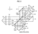
- Fig. 5 is an optical diagram of a demodulator which is disclosed in Patent Reference 1, and which uses a Michelson delay interferometer.
- a light beam S10 which is incident from incident means is split by a splitting portion 111 into two light beams S11, S12.
- the light beams S11, S12 are incident on the Michelson delay interferometer.
- Four interference outputs from the Michelson delay interferometer due to the input light beams S11, S12 are reflected by a mirror 116 or 117, and received by an optical detector 122 or 123 through a lens 118, 119, 120, or 121.
- These components constitute a demodulator for a DQPSK optical signal.
- the optical detector 122 is an optical fiber
- angle and axis deviations due to the mounting accuracy of the splitting portion 111, particularly the angle error in the rotation direction in the XY plane occur in the light incident on the optical fiber, thereby producing a problem in that the coupling efficiency with respect to the optical fiber is impaired.
- the reflected light in the split face is hardly adjusted because an angle deviation which is twice of that in the split face is generated. Furthermore, the angle error of the splitting portion in the rotation direction in the XY plane cannot be corrected by reflectors 113, 115.
- Exemplary embodiments of the present invention provide a delay interferometer in which position and angle errors of a splitting portion are minimized and the performance is enhanced.
- the invention is configured in the following manners.
- the reflectors are placed to be adjustable in at least one of X-axis, Y-axis, ⁇ X-axis, and ⁇ Y-axis directions with respect to a bottom face of the package.
- optical axis deviations of the first interference output light and second interference output light which are output from the Michelson delay interferometer unit are corrected by adjustment of the reflectors in at least one of X-axis, Y-axis, ⁇ X-axis, and ⁇ Y-axis directions.
- the beam splitter and at least one of the reflectors are integrally structured by a same material.
- Fig. 1 is a functional block diagram showing an embodiment of a delay interferometer to which the invention is applied.
- the embodiment is a small delay interferometer having a package configuration in which a Michelson delay interferometer unit is mounted in a package having first and second sidewall portions that are perpendicular to each other, and an output port for one interference output light, and an output port for the other interference output light are perpendicularly distributed in the first and second sidewall portions, respectively.
- a Michelson delay interferometer unit 2 is mounted in a quadrilateral package 1 having in the first and second sidewall portions 1a, 1b that are perpendicular to each other.
- Input light Li is input into the Michelson delay interferometer unit 2 through an input port 3 disposed in the first sidewall portion 1a.
- the Michelson delay interferometer unit 2 includes a splitting portion 21, a beam splitter 22 which is connected to the splitting portion 21, a first reflector 23, and a second reflector 24.
- the Michelson delay interferometer unit 2 optically processes light fluxes of A and B channels which have been split by the splitting portion 21.
- a feature of the invention is that the splitting portion 21 and the beam splitter 22 are integrally structured.
- the splitting portion 21 and beam splitter 22 in which the dimensional accuracy is ensured by a highly accurate polishing process are integrated with each other, the positional and angular accuracies of the split light fluxes can be improved.
- the embodiment operates on the same principle as the Michelson delay interferometer disclosed in Patent Reference 1 shown in Fig. 5 .
- the input light Li which is modulated by DQPSK is split into A and B channels by the splitting portion 21, and then optically processed.
- first interference output light and second interference output light are output.
- the A-channel first interference output light L1A is output from an A-channel first output port 4A disposed in the first sidewall portion 1a
- the A-channel second interference output light L2A is output from an A-channel second output port 5A disposed in the second sidewall portion 1b.
- the B-channel first interference output light L1B is output from a B-channel first output port 4B disposed in the first sidewall portion 1a
- the B-channel second interference output light L2B is output from a B-channel second output port 5B disposed in the second sidewall portion 1b.
- first and second optical axis shifting members 61, 62 each of which is formed by a parallel prism are inserted into optical paths of the B-channel first interference output light L1B and the B-channel second interference output light L2B, respectively.
- optical axis shifting members 61, 62 eliminate restrictions of the distances between the ports disposed in the sidewall portions, and reduce the sizes of the components of the Michelson delay interferometer unit 2, thereby contributing to the design of the miniaturized package 1.
- First and second optical path length compensating members 71, 72 each of which is formed by a rectangular prism correct the optical path lengths of the A-channel first interference output light L1A and the A-channel second interference output light L2A, i.e., the optical path length difference caused by the splitting portion 21 and the optical axis shifting members 61, 62, thereby contributing to a higher accuracy.
- the first and second optical path length compensating members 71, 72 increase the optical path lengths of the A-channel interference output light.
- the optical path length compensating members may be inserted into the B channel depending on the design of the splitting portion 21. Namely, the optical path length compensating members are inserted into the channel in which reduction of optical path lengths is performed.
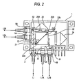
- Fig. 2 is a plan view showing in detail the configuration of the embodiment of Fig. 1 .
- the Michelson delay interferometer unit 2 mounted in the package 1 includes: the beam splitter 22 which is joined to the splitting portion 21 to optically process A-channel input light and B-channel input light; the first reflector 23; the second reflector 24; an A-channel phase adjusting plate 25A; and a B-channel phase adjusting plate 25B.
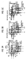
- Figs. 3A to 3C are plan views showing optical paths of the A and B channels in the configuration of Fig. 2 .
- Fig. 3A shows optical paths of the split of the A and B channels
- Fig. 3B shows those of the A channel
- Fig. 3B shows those of the B channel
- the input light Li which is incident through the input port 3 is passed through a lens to be converted to substantially parallel light, and then incident on the splitting portion 21.
- the incident substantially parallel light flux is split into transmitted light and reflected light by an NPBS film of the splitting portion 21.
- the light transmitted through the NPBS film is totally reflected by a total reflection surface to be formed as an A-channel light flux, and the light reflected by the NPBS film of the splitting portion 21 is formed as a B-channel light flux.
- the A-channel and B-channel light fluxes are incident on the beam splitter 22 including first and second NPBS films 22a, 22b.
- the light flux A which is incident on the beam splitter 22 is split into reflected light A-1 and transmitted light A-2 by the first NPBS film 22a of the beam splitter 22.
- the reflected light A-1 is returned by the first reflector 23
- the transmitted light A-2 is returned by the second reflector 24, and the both are then incident on the second NPBS film 22b of the beam splitter 22.
- the transmitted light which is formed by causing the reflected light A-1 to be transmitted through the NPBS film 22b, and the reflected light which is formed by causing the transmitted light A-2 to be reflected by the NPBS film 22b are output as the A-channel first interference output light L1A to the A-channel first output port 4A.
- the A-channel first interference output light L1A is the output the Michelson delay interferometer which is determined by the positions of the first and second reflectors 23, 24, i.e., the optical path length difference between the reflected light A-1 and the transmitted light A-2.
- the reflected light which is formed by causing the reflected light A-1 to be reflected by the NPBS film 22b, and the transmitted light which is formed by causing the transmitted light A-2 to be transmitted through the NPBS film 22b are output as the A-channel second interference output light L2A to the A-channel second output port 5A.
- the B-channel first interference output light L1B is output to the B-channel first output port 4B
- the B-channel second interference output light L2B is output to the B-channel second output port 5B.
- the first and second reflectors 23, 24 are placed to be adjustable in at least one of X-axis, Y-axis, ⁇ X-axis, and ⁇ Y-axis directions with respect to a bottom face of the package 1.
- Optical axis deviations of the first interference output light L1A or L1B and second interference output light L2A or L2B which are output from the Michelson delay interferometer unit 2 are corrected by adjustment of the first and second reflector 23, 24 in at least one of X-axis, Y-axis, ⁇ X-axis, and ⁇ Y-axis directions. Therefore, it is possible to realize a high-performance delay interferometer in which the optical axis accuracy that cannot be adjusted by the reflectors can be improved.
- the B-channel first and second interference output light L1B, L2B are supplied into the respective output ports through the first and second optical axis shifting members 61, 62.
- the A-channel first and second interference output light L1A, L2A are supplied into the respective output ports through the first and second optical path length compensating members 71, 72.
- a thin-film heater is formed on the A-channel phase adjusting plate 25A which is inserted in the optical path of the reflected light A-1.
- the refractive index of the phase adjusting plate 25A is changed, and the optical path length is equivalently changed, whereby the interference spectrum of the A-channel interference output light can be adjusted.
- the B-channel phase adjusting plate 25B inserted in the optical path of the reflected light B-1 can adjust the interference spectrum of the B-channel interference output light.
- a thin-film heater is formed on the B-channel phase adjusting plate 25B, and when an electric power is supplied to the heater, the refractive index of the phase adjusting plate 25B is changed, and the optical path length is equivalently changed, whereby the interference spectrum of the B-channel interference output light can be adjusted.
- Fig. 4 is a plan view showing another embodiment of the invention.
- the embodiment is characterized in that the functions of the beam splitter 22 and the second reflector 24 are integrally structured by the same material, to be configured as an integrated beam splitter 26.
- the optical path length therein can be equivalently shortened because the material has a high refractive index (for example, about 1.5), and therefore the package size can be further reduced.
- the beam splitter 22 and the first reflector 23 can be integrated with each other. When these components are integrated with each other, it is possible to realize a performance improvement in which the optical path length change due to the difference of the coefficients of thermal expansion is minimized.
- the delay interferometer has the configuration where the package has the perpendicular wall portions, and the input and output ports are perpendicularly disposed in the wall portions
- the invention is versatile, and is not restricted by the shape of the package.
Landscapes
- Physics & Mathematics (AREA)
- Engineering & Computer Science (AREA)
- Computer Networks & Wireless Communication (AREA)
- Signal Processing (AREA)
- General Physics & Mathematics (AREA)
- Optics & Photonics (AREA)
- Electromagnetism (AREA)
- Optical Modulation, Optical Deflection, Nonlinear Optics, Optical Demodulation, Optical Logic Elements (AREA)
- Optical Communication System (AREA)
- Instruments For Measurement Of Length By Optical Means (AREA)
- Optical Couplings Of Light Guides (AREA)
Applications Claiming Priority (1)
| Application Number | Priority Date | Filing Date | Title |
|---|---|---|---|
| JP2008152239A JP4895052B2 (ja) | 2008-06-10 | 2008-06-10 | 遅延干渉計 |
Publications (1)
| Publication Number | Publication Date |
|---|---|
| EP2134009A2 true EP2134009A2 (fr) | 2009-12-16 |
Family
ID=41120040
Family Applications (1)
| Application Number | Title | Priority Date | Filing Date |
|---|---|---|---|
| EP09161987A Withdrawn EP2134009A2 (fr) | 2008-06-10 | 2009-06-05 | Interféromètre à retard |
Country Status (3)
| Country | Link |
|---|---|
| US (1) | US20090304394A1 (fr) |
| EP (1) | EP2134009A2 (fr) |
| JP (1) | JP4895052B2 (fr) |
Families Citing this family (5)
| Publication number | Priority date | Publication date | Assignee | Title |
|---|---|---|---|---|
| JP4893969B2 (ja) * | 2008-06-10 | 2012-03-07 | 横河電機株式会社 | 遅延干渉計 |
| JP4636449B2 (ja) * | 2008-06-10 | 2011-02-23 | 横河電機株式会社 | 遅延干渉計 |
| JP4715872B2 (ja) * | 2008-06-10 | 2011-07-06 | 横河電機株式会社 | 遅延干渉計 |
| JP5923003B2 (ja) | 2012-07-11 | 2016-05-24 | 日本オクラロ株式会社 | 光受信器 |
| CN103885177B (zh) * | 2012-12-21 | 2017-09-12 | 上海矽睿科技有限公司 | 光纤放大器动态增益斜率均衡器及其制备工艺 |
Citations (1)
| Publication number | Priority date | Publication date | Assignee | Title |
|---|---|---|---|---|
| JP2008152239A (ja) | 2006-11-22 | 2008-07-03 | Asahi Glass Co Ltd | ネガ型感光性組成物ならびにこれを用いた硬化膜およびその製造方法 |
-
2008
- 2008-06-10 JP JP2008152239A patent/JP4895052B2/ja not_active Expired - Fee Related
-
2009
- 2009-06-03 US US12/477,526 patent/US20090304394A1/en not_active Abandoned
- 2009-06-05 EP EP09161987A patent/EP2134009A2/fr not_active Withdrawn
Patent Citations (1)
| Publication number | Priority date | Publication date | Assignee | Title |
|---|---|---|---|---|
| JP2008152239A (ja) | 2006-11-22 | 2008-07-03 | Asahi Glass Co Ltd | ネガ型感光性組成物ならびにこれを用いた硬化膜およびその製造方法 |
Also Published As
| Publication number | Publication date |
|---|---|
| US20090304394A1 (en) | 2009-12-10 |
| JP2009300539A (ja) | 2009-12-24 |
| JP4895052B2 (ja) | 2012-03-14 |
Similar Documents
| Publication | Publication Date | Title |
|---|---|---|
| JP5737874B2 (ja) | 復調器及び光送受信機 | |
| EP2134009A2 (fr) | Interféromètre à retard | |
| CN101782368A (zh) | 一种干涉仪装置 | |
| CN103270443B (zh) | 光学模块及其制造方法 | |
| EP2134010A2 (fr) | Interféromètre à retard | |
| CN110719132B (zh) | 用于调整光源的方法 | |
| JP5141189B2 (ja) | 干渉計及び波長測定装置 | |
| EP2134011A2 (fr) | Interféromètre à retard | |
| CN208953722U (zh) | 棱镜、棱镜组及光组件 | |
| US9008521B2 (en) | Optical receiver | |
| JP6566022B2 (ja) | 集積プリズム及び集積プリズムの構成方法 | |
| CN108292020B (zh) | 光学接收器及其装配方法 | |
| CN215769134U (zh) | 光接收次模块和光模块 | |
| US12140806B2 (en) | Optical module | |
| US8743370B2 (en) | Interferometer including elements that reflect beams moved in parallel in a direction substantially perpendicular to a substrate by reflection | |
| JP2017125926A (ja) | 光受信器 | |
| JP2012150327A (ja) | 2光束合波回路および復調器 |
Legal Events
| Date | Code | Title | Description |
|---|---|---|---|
| PUAI | Public reference made under article 153(3) epc to a published international application that has entered the european phase |
Free format text: ORIGINAL CODE: 0009012 |
|
| AK | Designated contracting states |
Kind code of ref document: A2 Designated state(s): AT BE BG CH CY CZ DE DK EE ES FI FR GB GR HR HU IE IS IT LI LT LU LV MC MK MT NL NO PL PT RO SE SI SK TR |
|
| STAA | Information on the status of an ep patent application or granted ep patent |
Free format text: STATUS: THE APPLICATION IS DEEMED TO BE WITHDRAWN |
|
| 18D | Application deemed to be withdrawn |
Effective date: 20120103 |