EP2134012A1 - Procede, systeme et appareil d'etablissement de canal de longueur d'onde - Google Patents
Procede, systeme et appareil d'etablissement de canal de longueur d'onde Download PDFInfo
- Publication number
- EP2134012A1 EP2134012A1 EP08757811A EP08757811A EP2134012A1 EP 2134012 A1 EP2134012 A1 EP 2134012A1 EP 08757811 A EP08757811 A EP 08757811A EP 08757811 A EP08757811 A EP 08757811A EP 2134012 A1 EP2134012 A1 EP 2134012A1
- Authority
- EP
- European Patent Office
- Prior art keywords
- wavelength
- path
- network node
- wavelength path
- network
- Prior art date
- Legal status (The legal status is an assumption and is not a legal conclusion. Google has not performed a legal analysis and makes no representation as to the accuracy of the status listed.)
- Withdrawn
Links
Images


Classifications
-
- H—ELECTRICITY
- H04—ELECTRIC COMMUNICATION TECHNIQUE
- H04Q—SELECTING
- H04Q11/00—Selecting arrangements for multiplex systems
- H04Q11/0001—Selecting arrangements for multiplex systems using optical switching
- H04Q11/0062—Network aspects
-
- H—ELECTRICITY
- H04—ELECTRIC COMMUNICATION TECHNIQUE
- H04B—TRANSMISSION
- H04B10/00—Transmission systems employing electromagnetic waves other than radio-waves, e.g. infrared, visible or ultraviolet light, or employing corpuscular radiation, e.g. quantum communication
- H04B10/25—Arrangements specific to fibre transmission
- H04B10/2507—Arrangements specific to fibre transmission for the reduction or elimination of distortion or dispersion
-
- H—ELECTRICITY
- H04—ELECTRIC COMMUNICATION TECHNIQUE
- H04J—MULTIPLEX COMMUNICATION
- H04J14/00—Optical multiplex systems
- H04J14/02—Wavelength-division multiplex systems
- H04J14/0227—Operation, administration, maintenance or provisioning [OAMP] of WDM networks, e.g. media access, routing or wavelength allocation
- H04J14/0241—Wavelength allocation for communications one-to-one, e.g. unicasting wavelengths
- H04J14/0242—Wavelength allocation for communications one-to-one, e.g. unicasting wavelengths in WDM-PON
- H04J14/0245—Wavelength allocation for communications one-to-one, e.g. unicasting wavelengths in WDM-PON for downstream transmission, e.g. optical line terminal [OLT] to ONU
- H04J14/0246—Wavelength allocation for communications one-to-one, e.g. unicasting wavelengths in WDM-PON for downstream transmission, e.g. optical line terminal [OLT] to ONU using one wavelength per ONU
-
- H—ELECTRICITY
- H04—ELECTRIC COMMUNICATION TECHNIQUE
- H04J—MULTIPLEX COMMUNICATION
- H04J14/00—Optical multiplex systems
- H04J14/02—Wavelength-division multiplex systems
- H04J14/0227—Operation, administration, maintenance or provisioning [OAMP] of WDM networks, e.g. media access, routing or wavelength allocation
- H04J14/0241—Wavelength allocation for communications one-to-one, e.g. unicasting wavelengths
- H04J14/0242—Wavelength allocation for communications one-to-one, e.g. unicasting wavelengths in WDM-PON
- H04J14/0249—Wavelength allocation for communications one-to-one, e.g. unicasting wavelengths in WDM-PON for upstream transmission, e.g. ONU-to-OLT or ONU-to-ONU
- H04J14/025—Wavelength allocation for communications one-to-one, e.g. unicasting wavelengths in WDM-PON for upstream transmission, e.g. ONU-to-OLT or ONU-to-ONU using one wavelength per ONU, e.g. for transmissions from-ONU-to-OLT or from-ONU-to-ONU
-
- H—ELECTRICITY
- H04—ELECTRIC COMMUNICATION TECHNIQUE
- H04J—MULTIPLEX COMMUNICATION
- H04J14/00—Optical multiplex systems
- H04J14/02—Wavelength-division multiplex systems
- H04J14/0227—Operation, administration, maintenance or provisioning [OAMP] of WDM networks, e.g. media access, routing or wavelength allocation
- H04J14/0254—Optical medium access
- H04J14/0256—Optical medium access at the optical channel layer
- H04J14/0257—Wavelength assignment algorithms
-
- H—ELECTRICITY
- H04—ELECTRIC COMMUNICATION TECHNIQUE
- H04J—MULTIPLEX COMMUNICATION
- H04J14/00—Optical multiplex systems
- H04J14/02—Wavelength-division multiplex systems
- H04J14/0227—Operation, administration, maintenance or provisioning [OAMP] of WDM networks, e.g. media access, routing or wavelength allocation
- H04J14/0254—Optical medium access
- H04J14/0267—Optical signaling or routing
-
- H—ELECTRICITY
- H04—ELECTRIC COMMUNICATION TECHNIQUE
- H04J—MULTIPLEX COMMUNICATION
- H04J14/00—Optical multiplex systems
- H04J14/02—Wavelength-division multiplex systems
- H04J14/0227—Operation, administration, maintenance or provisioning [OAMP] of WDM networks, e.g. media access, routing or wavelength allocation
- H04J14/0254—Optical medium access
- H04J14/0267—Optical signaling or routing
- H04J14/0271—Impairment aware routing
-
- H—ELECTRICITY
- H04—ELECTRIC COMMUNICATION TECHNIQUE
- H04J—MULTIPLEX COMMUNICATION
- H04J14/00—Optical multiplex systems
- H04J14/02—Wavelength-division multiplex systems
- H04J14/0227—Operation, administration, maintenance or provisioning [OAMP] of WDM networks, e.g. media access, routing or wavelength allocation
- H04J14/0254—Optical medium access
- H04J14/0256—Optical medium access at the optical channel layer
- H04J14/0258—Wavelength identification or labelling
-
- H—ELECTRICITY
- H04—ELECTRIC COMMUNICATION TECHNIQUE
- H04J—MULTIPLEX COMMUNICATION
- H04J14/00—Optical multiplex systems
- H04J14/02—Wavelength-division multiplex systems
- H04J14/0227—Operation, administration, maintenance or provisioning [OAMP] of WDM networks, e.g. media access, routing or wavelength allocation
- H04J14/0254—Optical medium access
- H04J14/0267—Optical signaling or routing
- H04J14/0269—Optical signaling or routing using tables for routing
-
- H—ELECTRICITY
- H04—ELECTRIC COMMUNICATION TECHNIQUE
- H04J—MULTIPLEX COMMUNICATION
- H04J14/00—Optical multiplex systems
- H04J14/02—Wavelength-division multiplex systems
- H04J14/0278—WDM optical network architectures
- H04J14/0279—WDM point-to-point architectures
-
- H—ELECTRICITY
- H04—ELECTRIC COMMUNICATION TECHNIQUE
- H04Q—SELECTING
- H04Q11/00—Selecting arrangements for multiplex systems
- H04Q11/0001—Selecting arrangements for multiplex systems using optical switching
- H04Q11/0062—Network aspects
- H04Q2011/0073—Provisions for forwarding or routing, e.g. lookup tables
-
- H—ELECTRICITY
- H04—ELECTRIC COMMUNICATION TECHNIQUE
- H04Q—SELECTING
- H04Q11/00—Selecting arrangements for multiplex systems
- H04Q11/0001—Selecting arrangements for multiplex systems using optical switching
- H04Q11/0062—Network aspects
- H04Q2011/0079—Operation or maintenance aspects
- H04Q2011/0081—Fault tolerance; Redundancy; Recovery; Reconfigurability
Definitions
- the present invention relates to the communication field, and in particular, to a method, a system, and a device for setting up a wavelength connection.
- the Multi-Protocol Label Switching (MPLS) protocol is extended to generate a Multi-Protocol Lambda-label Switching (MPLmS) protocol applicable to optical networks.
- MPLmS Multi-Protocol Lambda-label Switching
- the MPLmS protocol applies the basic MPLS concepts to the optical domain, and uses optical wavelength as a switching label.
- each network node floods the Traffic Engineering (TE) information, such as wavelength and penalty on their respective interface, to the network through a routing protocol, such as Open Shortest Path First with Traffic Engineering (OSPF-TE) protocol.
- OSPF-TE Open Shortest Path First with Traffic Engineering
- CSPF Constrained Shortest Path First
- the signaling protocol such as Resource Reservation Protocol with Traffic Engineering (RSVP-TE) protocol can set up an end-to-end connection automatically according to the calculated wavelength path.
- the optical wavelength signal is impaired during transmission. Impairment factors that affect optical signal performance include: power attenuation, dispersion, and noise. Such impairment factors affect performance of optical signals.
- the wavelength connection set up according to the wavelength path is unavailable. In order to keep the wavelength connection available, the impairment of the wavelength path cannot exceed a certain value.
- the path needs to be calculated and selected again until the path compliant with the impairment constraints is obtained. Afterward, a wavelength connection is set up according to the path, thus ensuring the wavelength connection to be available.
- the foregoing method for setting up an available wavelength connection involves many attempts of calculating and judging in order to obtain a wavelength path compliant with the impairment requirement, and an available wavelength connection can be set up according to the wavelength path only after such a wavelength path is obtained, thus bringing huge workload, enormous time consumption and low efficiency.
- a method, system and device for setting up a wavelength connection are disclosed in an embodiment of the present invention to set up an available wavelength channel efficiently, simply and quickly.
- a method for setting up a wavelength connection is disclosed in an embodiment of the present invention.
- the method includes:
- a path calculation server is disclosed in an embodiment of the present invention.
- the server includes:
- a network node device is disclosed in an embodiment of the present invention.
- the network node device includes:
- control server is disclosed in an embodiment of the present invention.
- the control server includes:
- a network communication system is disclosed in an embodiment of the present invention.
- the network communication system includes multiple network nodes, and further includes:
- the network nodes connect the wavelengths consecutively to set up a wavelength connection according to the wavelength path calculated out by the path calculation server, and perform impairment compensation for the wavelength signals in the interface according to the information about the wavelength impairment compensation of the wavelength path.
- the network communication system includes multiple network nodes.
- the network nodes include:
- the information about the wavelength impairment compensation of the wavelength path is obtained at the same time of obtaining the wavelength path between network nodes, impairment compensation is performed for the transmitted wavelength signals according to the wavelength impairment compensation information in the process of setting up the wavelength connection according to the wavelength path, thus setting up an available wavelength connection efficiently, simply and quickly.
- FIG. 1 shows a structure of a network communication system in an embodiment of the present invention
- FIG. 2 shows a structure of a network communication system in another embodiment of the present invention
- FIG. 3 shows layout of network nodes in a network communication system in another embodiment of the present invention
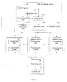
- FIG. 4 is flowchart of a method for setting up a wavelength connection in an embodiment of the present invention.
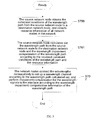
- FIG. 5 is flowchart of a method for setting up a wavelength connection in another embodiment of the present invention.
- a network communication system in an embodiment of the present invention includes a path calculation server and multiple network nodes.
- the path calculation server is configured to:
- the path calculation server includes a receiving unit 20, a calculating unit 21, and a sending unit 22.
- the receiving unit 20 is configured to: receive the request of calculating the wavelength path from the source network node to the destination network node, constraint conditions of the wavelength path, and resource information of all network nodes in the network.
- the receiving unit 20 may obtain the path calculation request and the wavelength path constraint conditions through an extended Path Computation Element Communication Protocol (PCECP).
- PCECP Path Computation Element Communication Protocol
- the wavelength path constraint conditions include: power attenuation tolerance of the path, Optical Signal Noise Ratio (OSNR) tolerance, dispersion tolerance, and Polarization Mode Dispersion (PMD) tolerance, or any combination thereof.
- OSNR Optical Signal Noise Ratio
- PMD Polarization Mode Dispersion
- the path calculation server needs to know the network resource information in order to calculate out an available wavelength path through the CSPF algorithm.
- the network resource information includes: interface of the network node, bandwidth of the link corresponding to the interface, penalty of the link corresponding to the interface, power attenuation of optical signals in the interface, adjustability of power parameters, variable range of power parameters, dispersion, adjustability of dispersion compensation parameters, variable range of dispersion compensation parameters, PMD, adjustability of PMD parameters, variable range of PMD parameters, power attenuation of the link connected to the interface, dispersion of the link connected to the interface, and PMD of the link connected to the interface.
- the receiving unit 20 may obtain the resource information of all network nodes from any network node through a routing protocol, such as an extended OSPF-TE. For example, in FIG. 1 , the receiving unit 20 obtains the network resource information from network node 1 through the OSPF-TE. In practice, the resource information may also be obtained in other modes, for example, each network node registers the resource information onto the path calculation server.
- a routing protocol such as an extended OSPF-TE.
- the calculating unit 21 is configured to calculate out the wavelength path between the network nodes and the wavelength impairment compensation information of the wavelength path according to the received constraint conditions of the wavelength path and resource information after the receiving unit 20 receives the request of calculating the wavelength path.
- the wavelength impairment compensation information includes the value or adjustment amount of the power and/or dispersion compensation and/or PMD compensation of wavelength signals in the interface of the network node.
- the path needs to be calculated and selected again until a path compliant with the impairment constraint conditions is selected, and then a wavelength connection is set up according to this path.
- the foregoing method for setting up an available wavelength connection involves many attempts of calculating and judging in order to obtain a wavelength path compliant with the impairment requirement, and an available wavelength connection can be set up according to the wavelength path only after such a wavelength path is obtained, thus bringing huge workload, enormous time consumption and low efficiency.
- the calculating unit 21 calculates out the information about the wavelength impairment compensation of the wavelength path, and an adjustable impairment compensation component is applied on the network node.
- the network node may adjust the impairment-related parameters in the path to meet the impairment constraint conditions according to the wavelength impairment compensation information calculated out by the path calculation server at the time of setting up the wavelength connection, without calculating or selecting the path again.
- the calculating unit 21 includes a first calculating unit 211, a second calculating unit 212, a judging unit 213, and an indicating unit 214.
- the first calculating unit 211 is configured to calculate out the wavelength path between two network nodes according to the resource information.
- the second calculating unit 212 is configured to calculate the impair parameters of the wavelength path obtained by the first calculating unit 211.
- the impairment factors that affect optical signals include power attenuation, dispersion, and noise. Therefore, the constraint conditions of the wavelength path may include: power attenuation tolerance of the path, OSNR tolerance, dispersion tolerance, PMD tolerance, or any combination thereof.
- the impairment parameters that need to be calculated depend on the constraint conditions. If a constraint is imposed on the OSNR of the wavelength path, it is necessary to calculate the OSNR value of the wavelength path.
- Pin1, Pin2, ..., PinN represent the input power of the amplifiers in the wavelength path
- NF1, NF2, ..., NFN represent noise factors of the corresponding amplifiers
- h is a constant
- w is a wavelength-related fixed value.
- different network nodes are connected through a fiber pair.
- Two fibers in the fiber pair are responsible for transmitting signals to the peer and receiving signals from the peer.
- An interface number is assigned to the fiber pair. That is, one interface corresponds to two optical jacks.
- One optical jack is a transmitting end, namely, source, and the other is a receiving end, namely, sink.
- An amplifier is deployed at both the transmitting end and the receiving end of each interface.
- the input power of an amplifier has a default value. If an adjustable power regulating unit or dispersion compensating unit is applied, the input power or the dispersion compensation may be adjusted for a single wavelength.
- the path calculation server needs to know whether the input power Pin of the amplifier in the network node, adjustability of Pin, variable range of Pin, noise factor, and other resource information.
- resource information may be obtained through the routing protocol.
- a network node can flood the information, for example, power of the interface of the network node, adjustability of the power, variable range, and noise factor, to the path calculation server through the OSPF-TE protocol. Therefore, the existing OSPF-TE protocol needs to be extended by adding a sub-TLV to the Type-Length-Value (TLV) parameter of the OSPF-TE link.
- TLV Type-Length-Value
- the format of the Value part of the sub-TLV is as follows: "Parameter Type" indicates type of the parameter, and the value "1" indicates that the type of the parameter is interface power.
- the F flag bit indicates whether the parameter is adjustable: “0" means that the parameter is not adjustable, and "1" means that the parameter is adjustable.
- the P flag bit indicates the position: "0" indicates adjusting the power of the receiving end amplifier, and "1" indicates adjusting the power of the transmitting end amplifier. If the power parameter of the receiving end and the power parameter of the transmitting end of a wavelength need to be released simultaneously, two interface power parameter sub-TLVs need to be carried.
- NF represents the noise factor of the amplifier corresponding to the interface.
- Value 1 represents the default value of the input power of the amplifier corresponding to the interface; and Value 2 represents the variable range of the input power.
- each network node can flood the optical signal power parameter in the interface of the network node to the path calculation server, and the path calculation server can use such information to calculate the OSNR of the path.
- Path dispersion derives from the dispersion introduced by the fiber.
- the dispersion amount introduced by the fiber is equal to the fiber dispersion coefficient multiplied by the fiber length. Therefore, once the fiber length is known, the dispersion amount introduced by the fiber can be obtained.
- various optical components on the path also introduce a dispersion amount. Such dispersion amount can be obtained through the parameter table of the optical component.
- the dispersion amount introduced by all sections of the fiber is added to the dispersion amount introduced by all the optical components, namely, the sum of dispersion, to obtain the dispersion amount of the whole path.
- Optical signals have a certain dispersion tolerance.
- a dispersion compensation apparatus is generally deployed in an optical transmission system to perform either optical compensation or electrical compensation, and may be a fixed dispersion compensation apparatus or an adjustable dispersion compensation apparatus.
- the final dispersion amount of the path is the foregoing sum of dispersion minus the compensation amount of the dispersion compensation apparatus.
- the dispersion compensation information of the optical signals in the network node interface can also be flooded to the path calculation server by extending the OSPF-TE protocol in the same way as flooding the power parameter.
- the processing mode which takes other constraint conditions into consideration is similar to the foregoing processing mode, and is not repeated here any further.
- the judging unit 213 is configured to judge whether the wavelength path impairment parameter calculated out by the second calculating unit 212 meets the impairment requirement indicated by the wavelength path constraint conditions received by the receiving unit 20.
- the indicating unit 214 is configured to generate the corresponding wavelength impairment compensation information according to the wavelength path constraint conditions and the resource information after receiving a negative judgment result output by the judging unit 213.
- the wavelength impairment compensation information may include the value of at least one of these parameters: power of the wavelength signal in the interface of the network node, dispersion compensation, and PMD compensation; and may also include the adjustment amount of at least one of these parameters: power of the wavelength signal in the interface of the network node, dispersion compensation, and PMD compensation.
- this embodiment supposes that a wavelength connection from the source network node to the destination network node needs to be set up, this wavelength connection needs to pass through the intermediate network node x, and the wavelength path constraint condition which needs to be fulfilled by the connection is that the minimum OSNR value of the wavelength connection to be set up is OSNR1.
- the resource information reveals that the power of the source network node is adjustable and its variable range is 1-6 dB, and the power of the intermediate network node x is also adjustable and its variable range is 0.1-20 dB.
- the judging unit 213 determines that the calculated OSNR of the wavelength path does not meet the requirement of being at least OSNR1.
- the indicating unit 214 can generate this impairment compensation information: adjusting the power by 2 dB when the source network node sets up the wavelength connection, and adjusting the power by 1 dB when the intermediate network node x sets up the wavelength connection. Therefore, in the process of setting up the wavelength connection, the corresponding network node can adjust the corresponding impairment parameters according to the compensation information, let the parameters meet the constraint requirement indicated by the wavelength impairment constraint condition of the wavelength path, and set up an available wavelength connection.
- the sending unit 22 is configured to send the wavelength path calculated out by the calculating unit 21 and the wavelength impairment compensation information of the wavelength path.
- the wavelength path impairment compensation information may be sent by extending the path calculation response message.
- Each network node (the source network node, intermediate network node x, and destination network node are illustrated in the figure) further includes a connecting unit 10 and a compensating unit 11.
- the compensating unit 11 adjusts the relevant parameters of the network node according to the wavelength impairment compensation information calculated out by the path calculation server to make the wavelength path impairment meet the constraint condition of wavelength path impairment.
- the connecting unit 10 connects the wavelengths compensated by the compensating unit 11 according to the wavelength path information calculated out, and sets up an available wavelength connection.
- the RSVP-TE protocol may be extended to notify each interface in the wavelength path to connect wavelengths automatically, and notify each network node to adjust the relevant parameters of the relevant wavelengths in each interface and make the wavelength path impairment meet requirements.
- An adjustment parameter subobject may be added to the ERO object of the RSVP-TE protocol so as to notify each network node to adjust the relevant parameters of the relevant wavelengths in each interface and make the wavelength path impairment meet requirements.
- the composition of the extended object is as follows: "Type” is set to 5; and “Parameter Type” has different values ("1” indicates adjusting the power, “2” indicates adjusting dispersion compensation, and “3” indicates PMD compensation), the P flag bit indicates the position of the adjustment ("0” indicates adjusting the parameter of the receiving end, and "1” indicates adjusting the parameter of the transmitting end; if the parameter of the receiving end and the parameter of the transmitting end of an interface need to be adjusted simultaneously, two adjustment parameter subobjects need to be carried), and "Value” represents the adjustment value.
- RFC3209 serves as a reference.
- the available path information can be expressed completely through the interface subobject and label subobject (wavelength subobject, see also draft-rabbat-ccamp-gmpls-lambda-labels-00.txt) defined in the RSVP-TE protocol and through the adjustment parameter subobjects defined above.
- the network nodes along the route may look up the subobjects in the ERO to connect wavelengths in different interfaces and adjust the relevant parameters.
- the network node may be instructed through the RSVP-TE protocol to connect wavelengths in different interfaces, and adjust the power, dispersion compensation, and PMD compensation for the wavelengths.
- a network communication system in another embodiment of the present invention includes multiple network nodes, a path calculation server and a control server.
- FIG. 2 shows a source network node, an intermediate network node x, a destination network node, a path calculation server, and a control server in a wavelength connection in this embodiment.
- the wavelength connection in this embodiment is not set up by sending signaling which instructs the wavelengths to be connected automatically; instead, the control server controls each interface in the wavelength path to connect wavelengths automatically, and notifies each network node to adjust the relevant parameters of the relevant wavelengths in each interface and make the wavelength path impairment meet requirements.
- the path calculation server sends the wavelength path calculated out and the information about impairment compensation of the wavelength path to the control server.
- the control server controls multiple network nodes to connect wavelengths consecutively and set up a wavelength connection according to the wavelength path calculated out by the path calculation server, and controls the network node to perform impairment compensation for the wavelength signals in the interface according to the information about the wavelength impairment compensation of the wavelength path.
- the control server further includes:
- both the information about the wavelength path and the wavelength impairment compensation information of the wavelength path are calculated out by the path calculation server in the network.
- the information about the wavelength path and the wavelength impairment compensation information of the wavelength path may be set by the network manager, or calculated out through the source network node of a specific wavelength connection. The mode of calculating such information through the source network node is similar to that of the path calculation server.
- a network communication system in another embodiment of the present invention includes multiple network nodes.
- FIG. 3 shows a structure of one of the multiple network nodes.
- the network node includes:
- the connecting unit 52 and the compensating unit 53 may also perform automatic connection of the wavelengths of the interfaces in the wavelength path according to the extended RSVP-TE protocol, and automatically adjust the relevant parameters of the relevant wavelengths in each interface and make the wavelength path impairment meet requirements.
- a network communication system in another embodiment of the present invention includes multiple network nodes and a control server.
- the control server controls multiple network nodes to connect the wavelengths consecutively to set up a wavelength connection according to the wavelength path calculated out by the network node, and controls the corresponding network nodes to perform impairment compensation for the wavelength in the interface according to the information about the wavelength impairment compensation of the wavelength path.
- FIG. 4 is flowchart of a method for setting up a wavelength connection in this embodiment. The method includes the following steps:
- Step 600 The path calculation server receives a request of calculating the wavelength path, constraint conditions of the wavelength path, and resource information of all network nodes in the network.
- the path calculation server may obtain the request of calculating the trail and the constraint conditions of the wavelength path through the extended PCECP protocol.
- the impairment factors that affect optical signals include power attenuation, dispersion, and noise. Therefore, the constraint conditions of the wavelength path may include: power attenuation tolerance of the path, OSNR tolerance, dispersion tolerance, PMD tolerance, or any combination thereof. Meanwhile, the path calculation server needs to know the network resource information in order to calculate out an available wavelength path through the CSPF algorithm.
- the network resource information includes: interface of the network node, bandwidth of the link corresponding to the interface, penalty of the link corresponding to the interface, power attenuation of optical signals in the interface, adjustability of power parameters, variable range of power parameters, dispersion, adjustability of dispersion compensation parameters, variable range of dispersion compensation parameters, PMD, adjustability of PMD parameters, variable range of PMD parameters, power attenuation of the link connected to the interface, dispersion of the link connected to the interface, and PMD of the link connected to the interface.
- the path calculation server may obtain the resource information of all network nodes from any network node through a routing protocol, such as extended OSPF-TE, or obtain the resource information in other modes, for example, each network node registers the resource information onto the path calculation server.
- a network node can flood the information, for example, power of the interface of the network node, adjustability of the power, variable range, and noise factor, to the path calculation server through the OSPF-TE protocol. Therefore, the existing OSPF-TE protocol needs to be extended by adding a sub-TLV to the TLV parameter of the OSPF-TE link.
- the format of the Value part of the sub-TLV is as follows: "Parameter Type" indicates type of the parameter, and the value "1" indicates that the type of the parameter is interface power.
- the F flag bit indicates whether the parameter is adjustable: "0" means that the parameter is not adjustable, and "1" means that the parameter is adjustable.
- the P flag bit indicates the position: "0" indicates adjusting the power of the receiving end amplifier, and "1" indicates adjusting the power of the transmitting end amplifier. If the power parameter of the receiving end and the power parameter of the transmitting end of a wavelength need to be released simultaneously, two interface power parameter sub-TLVs need to be carried.
- NF represents the noise factor of the amplifier corresponding to the interface.
- Value 1 represents the default value of the input power of the amplifier corresponding to the interface; and Value 2 represents the variable range of the input power.
- each network node can flood the parameter of its interface to the path calculation server.
- path dispersion derives from the dispersion introduced by the fiber, and the dispersion amount introduced by the fiber is equal to the fiber dispersion coefficient multiplied by the fiber length. Therefore, once the fiber length is known, the dispersion amount introduced by the fiber can be obtained. Meanwhile, various optical components on the path also introduce a certain dispersion amount. Such dispersion amount can be obtained through the parameter table of the optical component.
- Step S601 Calculation is performed to obtain the wavelength path between network nodes and the wavelength impairment compensation of the wavelength path according to the received constraint conditions of the wavelength path and the resource information.
- the obtaining of the wavelength path is the same as that in the prior art, and is not repeated here any further.
- the obtaining of the wavelength impairment compensation information of the wavelength path includes:
- different network nodes are connected through a fiber pair.
- Two fibers in the fiber pair are responsible for transmitting signals to the peer and receiving signals from the peer.
- An interface number is assigned to the fiber pair. That is, one interface corresponds to two optical jacks.
- One optical jack is a transmitting end, namely, source, and the other is a receiving end, namely, sink.
- An amplifier is deployed at both the transmitting end and the receiving end of each interface.
- the input power of an amplifier has a default value. If an adjustable power regulating unit or dispersion compensating unit is applied, the input power or the dispersion compensation may be adjusted for a single wavelength.
- the path calculation server needs to know whether the input power Pin of the amplifier in the network node, adjustability of Pin, variable range of Pin, noise factor, and other resource information.
- resource information can be obtained through the routing protocol.
- a network node can flood the information, for example, power of the interface of the network node, adjustability of the power, variable range, and noise factor, to the path calculation server through the OSPF-TE protocol. Therefore, the existing OSPF-TE protocol needs to be extended by adding a sub-TLV to the TLV parameter of the OSPF-TE link.
- the format of the Value part of the sub-TLV is as follows: "Parameter Type” indicates type of the parameter, and the value "1" indicates that the type of the parameter is interface power.
- the F flag bit indicates whether the parameter is adjustable: “0” means that the parameter is not adjustable, and “1” means that the parameter is adjustable.
- the P flag bit indicates the position: “0” indicates adjusting the power of the receiving end amplifier, and "1” indicates adjusting the power of the transmitting end amplifier. If the power parameter of the receiving end and the power parameter of the transmitting end of a wavelength need to be released simultaneously, two interface power parameter sub-TLVs need to be carried.
- NF represents the noise factor of the amplifier corresponding to the interface.
- Value 1 represents the default value of the input power of the amplifier corresponding to the interface; and Value 2 represents the variable range of the input power.
- each network node can flood the power parameter in the interface of the network node to the path calculation server, and the path calculation server can use such information to calculate the OSNR of the path.
- Path dispersion derives from the dispersion introduced by the fiber.
- the dispersion amount introduced by the fiber is equal to the fiber dispersion coefficient multiplied by the fiber length. Therefore, once the fiber length is known, the dispersion amount introduced by the fiber can be obtained.
- various optical components on the path also introduce a certain dispersion amount. Such dispersion amount can be obtained through the parameter table of the optical component.
- the dispersion amount introduced by all sections of the fiber is added to the dispersion amount introduced by all the optical components, namely, the sum of dispersion, to obtain the dispersion amount of the whole path.
- Optical signals have a certain dispersion tolerance.
- a dispersion compensation apparatus is generally deployed in an optical transmission system to perform either optical compensation or electrical compensation, and may be a fixed dispersion compensation apparatus or an adjustable dispersion compensation apparatus.
- the final dispersion amount of the path is the foregoing sum of dispersion minus the compensation amount of the dispersion compensation apparatus.
- the dispersion compensation information of the optical signals in the network node interface can also be flooded to the path calculation server by extending the OSPF-TE protocol in the same way as flooding the power parameter.
- the processing mode which takes other constraint conditions into consideration is similar to the foregoing processing mode, and is not repeated here any further.
- This embodiment supposes that a wavelength connection from the source network node to the destination network node needs to be set up, this wavelength connection needs to pass through the intermediate network node x, and the wavelength path constraint condition which needs to be fulfilled by the connection is that the minimum OSNR value of the wavelength connection to be set up is OSNR1.
- the resource information reveals that the power of the source network node is adjustable and its variable range is 1-6 dB, and the power of the intermediate network node x is also adjustable and its variable range is 0.1-20 dB. It is determined that the calculated OSNR of the wavelength path does not meet the requirement of being at least OSNR1.
- the indicating unit can generate this impairment compensation information: adjusting the power by 2 dB when the source network node sets up the wavelength connection, and adjusting the power by 1 dB when the intermediate network node x sets up the wavelength connection.
- Step S602 The path calculation server sends the wavelength path calculated out and the wavelength impairment compensation information of the wavelength path to the corresponding network node that requests to calculate the wavelength path.
- Step S603 The network nodes connect the wavelengths consecutively to set up a wavelength connection according to the wavelength path calculated out, and perform impairment compensation for the wavelength signals in the interface according to the wavelength impairment compensation information of the wavelength path.
- the RSVP-TE protocol may be extended to notify each interface in the wavelength path to connect wavelengths automatically, and notify each network node to adjust the relevant parameters of the relevant wavelengths in each interface and make the wavelength path impairment meet requirements.
- An adjustment parameter subobject may be added to the ERO object of the RSVP-TE protocol so as to notify each network node to adjust the relevant parameters of the relevant wavelengths in each interface and make the wavelength path impairment meet requirements.
- composition of the extended object is as follows: "Type” is set to 5; and “Parameter Type” has different values ("1” indicates adjusting the power, “2” indicates adjusting dispersion compensation, and “3” indicates PMD compensation), the P flag bit indicates the position of the adjustment ("0” indicates adjusting the parameter of the receiving end, and “1” indicates adjusting the parameter of the transmitting end; if the parameter of the receiving end and the parameter of the transmitting end of an interface need to be adjusted simultaneously, two adjustment parameter subobjects need to be carried), and "Value” represents the adjustment value.
- RFC3209 serves as a reference.
- the available path information can be expressed completely through the interface subobject and label subobject (wavelength subobject, see also draft-rabbat-ccamp-gmpls-lambda-labels-00.txt) defined in the RSVP-TE protocol and through the adjustment parameter subobjects defined above.
- the network nodes along the route may look up the subobjects in the ERO to connect wavelengths in different interfaces and adjust the relevant parameters.
- the network node may be instructed through the RSVP-TE protocol to connect wavelengths in different interfaces, and adjust the power, dispersion compensation, and PMD compensation for the wavelengths.
- the control server controls each interface in the wavelength path to connect wavelengths automatically, and notifies each network node to adjust the relevant parameters of the relevant wavelengths in each interface and make the wavelength path impairment meet requirements.
- the path calculation server sends the wavelength path calculated out and the information about impairment compensation of the wavelength path to the control server.
- the control server controls multiple network nodes to connect the wavelengths consecutively to set up a wavelength connection according to the wavelength path calculated out by the path calculation server, and controls the corresponding network nodes to perform impairment compensation for the wavelength signal in the interface according to the information about the wavelength impairment compensation of the wavelength path.
- FIG. 5 is flowchart of a method for setting up a wavelength connection in another embodiment of the present invention. The method includes:
- Step S700 The source network node obtains the constraint conditions of the wavelength path from the source network node to a destination network node, and obtains resource information of all network nodes in the network.
- Step S701 The source network node calculates out the wavelength path from the source network node to the destination network node and the wavelength impairment compensation of the wavelength path according to the received constraint conditions of the wavelength path and the resource information.
- Step S702 All the network nodes connect the wavelengths consecutively to set up a wavelength connection according to the wavelength path calculated out, and perform impairment compensation for the wavelength signals in the interface according to the wavelength impairment compensation information of the wavelength path.
- This embodiment differs from the embodiment in FIG. 4 in that:
- the source network node of the wavelength connection automatically calculates the wavelength path and the wavelength impairment compensation of the wavelength path.
- the remaining part is the same as that in the embodiment illustrated in FIG. 4 , and is not repeated here any further.
- the information about the wavelength impairment compensation of the wavelength path is obtained at the same time of obtaining the wavelength path between network nodes, impairment compensation is performed for the wavelength in the interface according to the wavelength impairment compensation information in the process of setting up the wavelength connection according to the wavelength path, thus setting up an available wavelength connection efficiently, simply and quickly.
- the software product is stored in a medium, such as ROM/RAM, magnetic disk, and compact disk, and includes several instructions that enable a computer device, such as personal computer, server, or network device, to perform all or part of the methods in the embodiments of the present invention.
Landscapes
- Engineering & Computer Science (AREA)
- Computer Networks & Wireless Communication (AREA)
- Signal Processing (AREA)
- Physics & Mathematics (AREA)
- Electromagnetism (AREA)
- Optical Communication System (AREA)
- Data Exchanges In Wide-Area Networks (AREA)
Applications Claiming Priority (2)
| Application Number | Priority Date | Filing Date | Title |
|---|---|---|---|
| CN200710028772.6A CN101075956B (zh) | 2007-06-22 | 2007-06-22 | 一种波长通道的建立方法、系统及设备 |
| PCT/CN2008/071402 WO2009000198A1 (fr) | 2007-06-22 | 2008-06-20 | Procede, systeme et appareil d'etablissement de canal de longueur d'onde |
Publications (2)
| Publication Number | Publication Date |
|---|---|
| EP2134012A1 true EP2134012A1 (fr) | 2009-12-16 |
| EP2134012A4 EP2134012A4 (fr) | 2010-05-26 |
Family
ID=38976782
Family Applications (1)
| Application Number | Title | Priority Date | Filing Date |
|---|---|---|---|
| EP08757811A Withdrawn EP2134012A4 (fr) | 2007-06-22 | 2008-06-20 | Procede, systeme et appareil d'etablissement de canal de longueur d'onde |
Country Status (4)
| Country | Link |
|---|---|
| US (1) | US20090274464A1 (fr) |
| EP (1) | EP2134012A4 (fr) |
| CN (1) | CN101075956B (fr) |
| WO (1) | WO2009000198A1 (fr) |
Families Citing this family (19)
| Publication number | Priority date | Publication date | Assignee | Title |
|---|---|---|---|---|
| CN101075956B (zh) * | 2007-06-22 | 2010-08-04 | 华为技术有限公司 | 一种波长通道的建立方法、系统及设备 |
| CN101621446B (zh) * | 2008-06-30 | 2011-08-24 | 华为技术有限公司 | 一种路径计算方法及装置 |
| US8396364B2 (en) | 2009-02-06 | 2013-03-12 | Futurewei Technologies, Inc. | System and method for impairment-aware routing and wavelength assignment in wavelength switched optical networks |
| US8831424B2 (en) * | 2009-04-28 | 2014-09-09 | Cisco Technology, Inc. | Channel validation in optical networks using multi-channel impairment evaluation |
| CN101908942B (zh) | 2009-06-05 | 2014-10-08 | 华为技术有限公司 | 一种损伤信息传送方法、节点和网络系统 |
| CN102484555B (zh) * | 2009-08-21 | 2016-04-13 | 瑞典爱立信有限公司 | 光网络中的方法和节点实体 |
| CN102238060B (zh) * | 2010-04-21 | 2014-03-05 | 华为技术有限公司 | 一种路由选择方法和装置 |
| CN103370893B (zh) * | 2011-02-04 | 2017-03-08 | 瑞典爱立信有限公司 | 配置光路的方法、装置以及光通信网络节点 |
| CN102655472B (zh) * | 2011-03-04 | 2017-07-14 | 中兴通讯股份有限公司 | 一种利用分布式信令建立标签交换路径的方法及系统 |
| EP2706708B1 (fr) * | 2011-05-24 | 2015-09-16 | Huawei Technologies Co., Ltd. | Procédé et appareil de sélection de chemin |
| WO2013037426A1 (fr) | 2011-09-15 | 2013-03-21 | Telefonaktiebolaget L M Ericsson (Publ) | Restauration dans un réseau optique à commutation de longueurs d'onde (wson) |
| US8902788B2 (en) * | 2012-01-11 | 2014-12-02 | Alcatel Lucent | Method and system for energy efficient routing of IP packets over optical backbone networks |
| CN102665148A (zh) * | 2012-04-20 | 2012-09-12 | 北京联合大学 | 一种提高网络负载均衡性的波长分配方法及装置 |
| US20160308786A1 (en) * | 2015-04-17 | 2016-10-20 | Futurewei Technologies, Inc. | Temporal Tunnel Services |
| US10547543B2 (en) | 2015-06-24 | 2020-01-28 | Futurewei Technologies, Inc. | Elegant temporal label switched path tunnel service controller |
| US10200280B2 (en) | 2015-06-25 | 2019-02-05 | Futurewei Technologies, Inc. | Software-defined network for temporal label switched path tunnels |
| US10498640B2 (en) | 2015-09-04 | 2019-12-03 | Futurewei Technologies, Inc. | PCE for temporal tunnel services |
| US10841183B1 (en) * | 2019-10-18 | 2020-11-17 | Huawei Technologies Canada Co., Ltd. | Method and system for reliability-aware embedding of a virtual network onto an elastic optical network |
| CN113972949B (zh) * | 2020-07-23 | 2024-12-10 | 中兴通讯股份有限公司 | 业务单板配置方法、装置、设备及存储介质 |
Family Cites Families (6)
| Publication number | Priority date | Publication date | Assignee | Title |
|---|---|---|---|---|
| US7599621B2 (en) * | 2001-07-19 | 2009-10-06 | Alcatel-Lucent Usa Inc. | Trail engineering in agile photonic networks |
| CA2418384A1 (fr) * | 2002-02-06 | 2003-08-06 | Nippon Telegraph And Telephone Corporation | Reseau optique, appareil d'interconnexion optique, reseau ip photonique et noeud |
| JP4554298B2 (ja) * | 2004-08-20 | 2010-09-29 | 富士通株式会社 | 波長分割多重光伝送システム |
| JP4755457B2 (ja) * | 2005-07-15 | 2011-08-24 | 株式会社日立製作所 | 光ネットワーク装置及び光ネットワーク |
| CN1878047A (zh) * | 2006-07-19 | 2006-12-13 | 华为技术有限公司 | 扩散波分设备的交叉限制信息的方法 |
| CN101075956B (zh) * | 2007-06-22 | 2010-08-04 | 华为技术有限公司 | 一种波长通道的建立方法、系统及设备 |
-
2007
- 2007-06-22 CN CN200710028772.6A patent/CN101075956B/zh active Active
-
2008
- 2008-06-20 WO PCT/CN2008/071402 patent/WO2009000198A1/fr not_active Ceased
- 2008-06-20 EP EP08757811A patent/EP2134012A4/fr not_active Withdrawn
-
2009
- 2009-07-13 US US12/501,826 patent/US20090274464A1/en not_active Abandoned
Also Published As
| Publication number | Publication date |
|---|---|
| US20090274464A1 (en) | 2009-11-05 |
| EP2134012A4 (fr) | 2010-05-26 |
| CN101075956A (zh) | 2007-11-21 |
| WO2009000198A1 (fr) | 2008-12-31 |
| CN101075956B (zh) | 2010-08-04 |
Similar Documents
| Publication | Publication Date | Title |
|---|---|---|
| EP2134012A1 (fr) | Procede, systeme et appareil d'etablissement de canal de longueur d'onde | |
| JP3373332B2 (ja) | プリエンファシス方式光波長多重通信方法および装置 | |
| US8346078B2 (en) | Optical network equipment and optical network | |
| US8131155B2 (en) | Optical signal transmission apparatus | |
| JP4053389B2 (ja) | 光信号対雑音比のモニタ方法およびそれを用いた光伝送システム | |
| CN101808257B (zh) | 波长交换光网络中动态传输性能优化的方法及装置 | |
| US20090116833A1 (en) | Optical wavelength multiplexed transmission apparatus | |
| US7400830B2 (en) | Quality monitoring method and apparatus for wavelength division multiplexed optical signal and optical transmission system using the same | |
| CN101662704B (zh) | 获取光波长路径的方法、系统和节点设备 | |
| JP2001186107A (ja) | レベル調整方法並びにその方法を利用する波長多重伝送装置及びシステム | |
| US20140029937A1 (en) | Method, apparatus, and system for monitoring and adjusting optical power | |
| JP2012058252A (ja) | ファイバスパンの損失および分散の測定 | |
| CN101415131A (zh) | 一种光网络中基于信令的自适应传输控制方法 | |
| JP2008277893A (ja) | マルチレートponシステムとその局側装置、端末装置及び伝送レート設定方法 | |
| EP1394976A1 (fr) | Procédé de commande de puissance de canal dans un système WDM | |
| US20060013589A1 (en) | Optical transmission system and method of controlling optical transmission system | |
| JP4766565B2 (ja) | 光増幅器 | |
| JP2000174730A (ja) | 波長多重光伝送装置 | |
| CA2486640C (fr) | Optimisation de la puissance dans des reseaux de communications optiques | |
| CN101552690B (zh) | 一种节点维护功能的配置方法、系统及节点设备 | |
| WO2023024782A1 (fr) | Procédé et système de transmission de signal | |
| JP2006279726A (ja) | 光ネットワークシステム | |
| WO2016082613A1 (fr) | Procédé et système permettant de commander la puissance optique | |
| Zervas et al. | Experimental demonstration of a self-optimised multi-bit-rate optical network | |
| Wu et al. | A signaling-based approach to implement self-adaptive transmission control in impairment-aware transparent WDM networks |
Legal Events
| Date | Code | Title | Description |
|---|---|---|---|
| PUAI | Public reference made under article 153(3) epc to a published international application that has entered the european phase |
Free format text: ORIGINAL CODE: 0009012 |
|
| 17P | Request for examination filed |
Effective date: 20090630 |
|
| AK | Designated contracting states |
Kind code of ref document: A1 Designated state(s): AT BE BG CH CY CZ DE DK EE ES FI FR GB GR HR HU IE IS IT LI LT LU LV MC MT NL NO PL PT RO SE SI SK TR |
|
| A4 | Supplementary search report drawn up and despatched |
Effective date: 20100422 |
|
| RIC1 | Information provided on ipc code assigned before grant |
Ipc: H04B 10/18 20060101ALI20100416BHEP Ipc: H04J 14/02 20060101AFI20100416BHEP Ipc: H04B 10/12 20060101ALI20100416BHEP Ipc: H04Q 11/00 20060101ALI20100416BHEP |
|
| DAX | Request for extension of the european patent (deleted) | ||
| 17Q | First examination report despatched |
Effective date: 20121221 |
|
| STAA | Information on the status of an ep patent application or granted ep patent |
Free format text: STATUS: THE APPLICATION IS DEEMED TO BE WITHDRAWN |
|
| 18D | Application deemed to be withdrawn |
Effective date: 20130503 |