EP2134155B1 - Plateau pour la croissance d'une matière organique et ensemble pépinière - Google Patents
Plateau pour la croissance d'une matière organique et ensemble pépinière Download PDFInfo
- Publication number
- EP2134155B1 EP2134155B1 EP08737782.6A EP08737782A EP2134155B1 EP 2134155 B1 EP2134155 B1 EP 2134155B1 EP 08737782 A EP08737782 A EP 08737782A EP 2134155 B1 EP2134155 B1 EP 2134155B1
- Authority
- EP
- European Patent Office
- Prior art keywords
- tray
- leds
- heat
- substrate
- organic material
- Prior art date
- Legal status (The legal status is an assumption and is not a legal conclusion. Google has not performed a legal analysis and makes no representation as to the accuracy of the status listed.)
- Not-in-force
Links
- 239000011368 organic material Substances 0.000 title claims description 15
- 239000000758 substrate Substances 0.000 claims description 54
- 239000000463 material Substances 0.000 claims description 27
- 229920003023 plastic Polymers 0.000 claims description 9
- VVQNEPGJFQJSBK-UHFFFAOYSA-N Methyl methacrylate Chemical compound COC(=O)C(C)=C VVQNEPGJFQJSBK-UHFFFAOYSA-N 0.000 claims description 6
- 229920005372 Plexiglas® Polymers 0.000 claims description 6
- 239000011521 glass Substances 0.000 claims description 6
- 229910052751 metal Inorganic materials 0.000 claims description 6
- 239000002184 metal Substances 0.000 claims description 6
- 238000000034 method Methods 0.000 claims description 3
- 239000002689 soil Substances 0.000 description 9
- 238000010438 heat treatment Methods 0.000 description 7
- 239000007788 liquid Substances 0.000 description 7
- 238000012546 transfer Methods 0.000 description 7
- 238000001816 cooling Methods 0.000 description 5
- 239000011490 mineral wool Substances 0.000 description 4
- OKKJLVBELUTLKV-UHFFFAOYSA-N Methanol Chemical compound OC OKKJLVBELUTLKV-UHFFFAOYSA-N 0.000 description 3
- 230000001580 bacterial effect Effects 0.000 description 3
- 230000008901 benefit Effects 0.000 description 3
- 238000004113 cell culture Methods 0.000 description 3
- 238000013461 design Methods 0.000 description 3
- 230000012010 growth Effects 0.000 description 3
- 230000008635 plant growth Effects 0.000 description 3
- 230000009467 reduction Effects 0.000 description 3
- 239000012780 transparent material Substances 0.000 description 3
- 239000004020 conductor Substances 0.000 description 2
- 238000002955 isolation Methods 0.000 description 2
- 230000005855 radiation Effects 0.000 description 2
- XLYOFNOQVPJJNP-UHFFFAOYSA-N water Substances O XLYOFNOQVPJJNP-UHFFFAOYSA-N 0.000 description 2
- QGZKDVFQNNGYKY-UHFFFAOYSA-N Ammonia Chemical compound N QGZKDVFQNNGYKY-UHFFFAOYSA-N 0.000 description 1
- OAICVXFJPJFONN-UHFFFAOYSA-N Phosphorus Chemical compound [P] OAICVXFJPJFONN-UHFFFAOYSA-N 0.000 description 1
- XUIMIQQOPSSXEZ-UHFFFAOYSA-N Silicon Chemical compound [Si] XUIMIQQOPSSXEZ-UHFFFAOYSA-N 0.000 description 1
- 229910052782 aluminium Inorganic materials 0.000 description 1
- XAGFODPZIPBFFR-UHFFFAOYSA-N aluminium Chemical compound [Al] XAGFODPZIPBFFR-UHFFFAOYSA-N 0.000 description 1
- 238000004873 anchoring Methods 0.000 description 1
- 238000003491 array Methods 0.000 description 1
- 230000000712 assembly Effects 0.000 description 1
- 238000000429 assembly Methods 0.000 description 1
- 238000004140 cleaning Methods 0.000 description 1
- 239000002361 compost Substances 0.000 description 1
- 239000000110 cooling liquid Substances 0.000 description 1
- 230000008878 coupling Effects 0.000 description 1
- 238000010168 coupling process Methods 0.000 description 1
- 238000005859 coupling reaction Methods 0.000 description 1
- 239000000428 dust Substances 0.000 description 1
- 238000005516 engineering process Methods 0.000 description 1
- 239000000835 fiber Substances 0.000 description 1
- 239000011888 foil Substances 0.000 description 1
- 238000005286 illumination Methods 0.000 description 1
- 238000009413 insulation Methods 0.000 description 1
- 238000011835 investigation Methods 0.000 description 1
- 238000004519 manufacturing process Methods 0.000 description 1
- 238000012986 modification Methods 0.000 description 1
- 230000004048 modification Effects 0.000 description 1
- 239000002159 nanocrystal Substances 0.000 description 1
- 230000003287 optical effect Effects 0.000 description 1
- 229920000642 polymer Polymers 0.000 description 1
- 238000004382 potting Methods 0.000 description 1
- 239000000843 powder Substances 0.000 description 1
- 230000001737 promoting effect Effects 0.000 description 1
- 238000005057 refrigeration Methods 0.000 description 1
- 239000004065 semiconductor Substances 0.000 description 1
- 229910052710 silicon Inorganic materials 0.000 description 1
- 239000010703 silicon Substances 0.000 description 1
- 230000003595 spectral effect Effects 0.000 description 1
- 238000001228 spectrum Methods 0.000 description 1
- 239000002887 superconductor Substances 0.000 description 1
- 235000013311 vegetables Nutrition 0.000 description 1
- 235000012431 wafers Nutrition 0.000 description 1
Images


Classifications
-
- A—HUMAN NECESSITIES
- A01—AGRICULTURE; FORESTRY; ANIMAL HUSBANDRY; HUNTING; TRAPPING; FISHING
- A01G—HORTICULTURE; CULTIVATION OF VEGETABLES, FLOWERS, RICE, FRUIT, VINES, HOPS OR SEAWEED; FORESTRY; WATERING
- A01G9/00—Cultivation in receptacles, forcing-frames or greenhouses; Edging for beds, lawn or the like
- A01G9/04—Flower-pot saucers
- A01G9/045—Trays for receiving multiple pots
-
- A—HUMAN NECESSITIES
- A01—AGRICULTURE; FORESTRY; ANIMAL HUSBANDRY; HUNTING; TRAPPING; FISHING
- A01G—HORTICULTURE; CULTIVATION OF VEGETABLES, FLOWERS, RICE, FRUIT, VINES, HOPS OR SEAWEED; FORESTRY; WATERING
- A01G7/00—Botany in general
- A01G7/04—Electric or magnetic or acoustic treatment of plants for promoting growth
- A01G7/045—Electric or magnetic or acoustic treatment of plants for promoting growth with electric lighting
-
- A—HUMAN NECESSITIES
- A01—AGRICULTURE; FORESTRY; ANIMAL HUSBANDRY; HUNTING; TRAPPING; FISHING
- A01G—HORTICULTURE; CULTIVATION OF VEGETABLES, FLOWERS, RICE, FRUIT, VINES, HOPS OR SEAWEED; FORESTRY; WATERING
- A01G9/00—Cultivation in receptacles, forcing-frames or greenhouses; Edging for beds, lawn or the like
- A01G9/24—Devices or systems for heating, ventilating, regulating temperature, illuminating, or watering, in greenhouses, forcing-frames, or the like
- A01G9/249—Lighting means
-
- Y—GENERAL TAGGING OF NEW TECHNOLOGICAL DEVELOPMENTS; GENERAL TAGGING OF CROSS-SECTIONAL TECHNOLOGIES SPANNING OVER SEVERAL SECTIONS OF THE IPC; TECHNICAL SUBJECTS COVERED BY FORMER USPC CROSS-REFERENCE ART COLLECTIONS [XRACs] AND DIGESTS
- Y02—TECHNOLOGIES OR APPLICATIONS FOR MITIGATION OR ADAPTATION AGAINST CLIMATE CHANGE
- Y02A—TECHNOLOGIES FOR ADAPTATION TO CLIMATE CHANGE
- Y02A40/00—Adaptation technologies in agriculture, forestry, livestock or agroalimentary production
- Y02A40/10—Adaptation technologies in agriculture, forestry, livestock or agroalimentary production in agriculture
- Y02A40/25—Greenhouse technology, e.g. cooling systems therefor
-
- Y—GENERAL TAGGING OF NEW TECHNOLOGICAL DEVELOPMENTS; GENERAL TAGGING OF CROSS-SECTIONAL TECHNOLOGIES SPANNING OVER SEVERAL SECTIONS OF THE IPC; TECHNICAL SUBJECTS COVERED BY FORMER USPC CROSS-REFERENCE ART COLLECTIONS [XRACs] AND DIGESTS
- Y02—TECHNOLOGIES OR APPLICATIONS FOR MITIGATION OR ADAPTATION AGAINST CLIMATE CHANGE
- Y02P—CLIMATE CHANGE MITIGATION TECHNOLOGIES IN THE PRODUCTION OR PROCESSING OF GOODS
- Y02P60/00—Technologies relating to agriculture, livestock or agroalimentary industries
- Y02P60/14—Measures for saving energy, e.g. in green houses
Definitions
- the present invention relates to a tray for growing organic material.
- the invention further relates to a nursery assembly.
- a nursery assembly is known from US 4,914,858 .
- Said patent discloses a nursery assembly which is built up of a rack in which trays are accommodated. The trays are filled with a substrate into which seeds for germinating are inserted. Above each tray, a group of LEDs is situated. The heat emission from LEDs is minimal in comparison with that of light bulbs. This low radiation of heat enables the nurseryman to position the LEDs very close to the plant material.
- US 6,680,200 discloses an assembly for promoting the growth of plant tissues that includes a plurality of trays each defining an array of wells, wherein each well contains a tissue sample.
- a plurality of LED arrays mounted on a circuit board above each tray provides the light for the tissue samples in said trays.
- Each of the LEDs is centered above a respective one of the wells.
- JP 09-098665 discloses a plant cultivation apparatus capable of reducing electric power cost, such as illumination cost and refrigeration cost, while having an excellent growing performance and being useful for vegetable cultivation.
- a tray for growing organic material comprising a plurality of LEDs, the tray having an upper side and a lower side, the upper side being arranged to carry a substrate for growing organic material and the lower side being arranged to radiate the light generated by the LEDs, the tray comprising a structure enabling the tray to radiate more heat, generated by the LEDs, to the upper side of the tray than to the lower side of the tray.
- Organic material could be any plant or seed material, but also a bacterial culture or cell culture.
- the present invention is based on the recognition that the growth of plants can be improved by keeping the soil in which the roots are positioned above a certain temperature. For this reason black plastic is used in agriculture to cover the soil so as to enable a more efficient heating up of the soil below the plastic by the sunlight. This increases the average soil temperature, which improves the growth of plant material. According to the invention, the heat generated by the LEDs is not wasted.
- the tray according to the invention mainly transfers the generated heat to the substrate and not to the air.
- the tray functions as a floor heating device of the substrate. In this way the average temperature of the substrate could be higher than the air temperature. This enables the nurseryman to reduce further costs of heating or cooling the air, while the temperature of the substrate with the roots is kept above the desired substrate temperature.
- the embedding of LEDs in the tray enables the nurseryman to position more trays in an assembly.
- the floor heating function in combination with the function of lighting device is also advantageous in an embodiment of a substrate with a cell culture and bacterial culture, wherein the substrate is heated from below and not via the air above the culture.
- the structure comprises a first part and a second part, a side of the first part forming the upper side and a side of the second part forming the lower side of the tray, wherein the LEDs are attached on the first part and the first part has a higher thermal conductivity than the second part.
- the heat will be transferred mainly to the upper side of the tray.
- the higher the thermal conductivity the more the heat will be spread over a bigger surface of the upper side of the tray. This reduces the temperature variations in the substrate.
- a gap separates the first part and the second part.
- the gap which could be filled with air or another gas, functions as a thermal resistance between the first and the second part. In this way the heat generated by an LED will be transferred through the first part to the upper side of the tray.
- the material of the first part is at least one of the materials: metal, glass, Plexiglass, or plastic.
- the material of the second part is at least one of the transparent materials: glass, Plexiglass, or plastic.
- the surface of the first part facing the second part is reflective. This feature increases the lighting efficiency of the tray.
- the structure comprises one or more heat pipes, and the LEDs are thermally coupled to the one or more heat pipes. This feature enables to transfer quickly the heat from the LED to the lowest temperature of the heat pipe. In this way the tray evenly heats the substrate. This improves the growing of roots.
- the heat pipes are horizontally positioned. This feature enables to embed the heat pipes in a plate. By mounting the LEDs near to a heat pipe, the heat generated by the LED will be spread more evenly over the contact area of the tray and the substrate. Furthermore, this feature enables to use one heat pipe for a tray.
- the heat pipe could meander in a sinuous, spiral, or circular course over the tray. In another embodiment the heat pipe could extend horizontally from one side to another side of the tray.
- the heat pipes are positioned above a bottom layer, which bottom layer comprises areas for allowing passage of the light emitted by the LEDs.
- This embodiment enables to improve the efficiency of transfer of heat from the LED to the substrate.
- the LEDs have to be attached to the heat pipe to enable the heat pipe to transfer efficiently the generated heat from an LED to the soil.
- the bottom layer comprises transparent areas for allowing passage of the light generated by the LEDs to the plant material positioned below the tray.
- the heat pipes are vertically positioned. This feature reduces the temperature difference between the top of the substrate and the bottom of the substrate. A smaller temperature variation in the substrate results in a more uniform growth of roots in the substrate, irrespective of the depth of the substrate.
- a further aspect of the invention relates to a nursery assembly comprising a plurality of trays according to the claims, the trays being positioned above each other.
- Yet another aspect of the invention relates to a method of growing organic material, which method comprises the steps of:
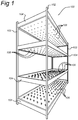
- Figure 1 shows a perspective view of a nursery assembly 100 built up of a rack 102 in which trays 104, 104' according to the invention are accommodated.
- the trays 104, 104' are detachably positioned in the rack 102.
- the trays 104, 104' in Figure 1 are filled with a substrate.
- seeds for germinating could be inserted or cultivated plants 106 could grow. Examples of a substrate are soil, potting compost, mineral wool or rock wool.
- the trays 104, 104' comprise a plurality of Light Emitting Diodes (LEDs) 108 at the bottom of a tray 104, 104'.
- LEDs Light Emitting Diodes
- LEDs embedded in a tray 104' radiate light upon the plant material in the tray 104 positioned below said tray 104'.
- LEDs have the advantage that the heat generated by the LED is not radiated in the form of Infra Red light (IR) in the beam. This has the advantage that the light source can be positioned close to the plant material.
- IR Infra Red light
- Figure 1 can be seen that the LEDs are uniformly distributed over the bottom of the tray 104'. This enables to provide uniform lighting conditions for the plant material 106.
- the heat generated by the LEDs is mainly transferred to the substrate to keep the roots of the plants above a certain temperature or at an optimal temperature for growing plants or germinating seeds.
- the structure of the tray is such that it functions as a floor-heating device and a lighting device.
- the air temperature can be reduced. This can lead to a reduction of the energy which is normally used to heat up the air in the space where plants grow. This will reduce the costs for producing plant material.
- the LEDs can be any "light-emitting element" that emits radiation in any region or combination of regions of the electromagnetic spectrum, for example, the visible region, the infrared and/or ultraviolet region, when activated by applying a potential difference across it or passing a current through it, for example. Therefore, the LED can have monochromatic, quasi-monochromatic, polychromatic or broadband spectral emission characteristics. Also a combination of LEDs with different wavelengths can be used in a single tray. One type with a wavelength optimized for the growth and another type with a wavelength optimal for e.g. the blooming stage of the plants.
- light-emitting elements include semiconductor, organic, or polymer/polymeric light emitting diodes, optically pumped phosphor coated light emitting diodes, optically pumped nano-crystal light-emitting diodes or any other similar light-emitting devices, as will be readily understood by a person skilled in the art.
- the rack and trays are provided with supply wires.
- a person skilled in the art knows how to install the supply wires and corresponding connections in the rack 102 and the trays 104, 104'. Therefore, this subject matter is not discussed in further detail.
- FIG. 2 shows schematically a cross section of a first embodiment of a tray 200 according to the invention.
- the tray comprises a top layer 202 and a bottom layer 206.
- LEDs 204 are embedded between the top layer 202 and the bottom layer 206.
- the LEDs 204 are attached to the top layer 202. This provides a good thermal coupling between a LED 204 and the top layer 202.
- the top layer 202 could be made of glass, metal, Plexiglass, plastic or any other material suitable for providing a tray for growing plants and conducting heat.
- a suitable metal is for example aluminum, which is a light material with a good thermal conductivity.
- the top layer 202 comprises a light-reflective surface 214.
- the light-reflective surface 214 increases the amount of light radiated via the bottom of the tray.
- the efficiency of the system can be even further improved by applying a white plastic foil around the plant (organic material). This improves the lighting efficiency of the tray 200.
- the bottom layer 206 is made of a transparent material such as glass, Plexiglass or plastic. Also a diffuser material could be used resulting in a homogenous emitting surface.
- the top layer 202 and bottom layer 206 are spaced from each other by means of a gap 203.
- the gap 203 is filled with air or any other suitable gas or liquid that forms a thermal insulation between the top layer 202 and the bottom layer 206.
- the heat dissipated by the LED 204 towards the top layer 202 will not easily be transferred to the bottom layer, but rather be passed to the substrate 210 in which plant material 208 is growing.
- the top layer 202 is made of a good heat conductive material, the top layer 202 will pass heat, evenly distributed over the contact area 216 with the substrate, to the substrate 210. In this way, more heat will be radiated to the substrate 210 above the tray 200 than to the air below the tray 200.
- the technology for manufacturing Metal Core Printed Circuit Boards could be used for mounting the LEDs on a layer of metal.
- thermal conductivity of the top layer is that the average operating temperature of the LEDs will decrease. A reduction of the operating temperature will increase the lighting efficiency of the LEDs. Furthermore, reduction of the average operating temperature will increase the lifetime of an LED.
- the space between the LED 204 and the bottom layer 206 could be minimal.
- the heat generated by the LEDs is dissipated at the rear side of the LEDs and transferred to the top layer 202.
- the bottom layer 206 could comprise collimators (not shown) provided in the beams of the LEDs.
- a collimator provides a light beam of a LED with the desired optical characteristics, such as beam angle and beam axis.
- the tray comprises a rim 212, to ensure that the substrate or water provided to the substrate will not spill from the tray 200.
- the flat surface of the tray as well as the top side and bottom side provide the tray with easy cleaning characteristics.
- the two layers 202, 206 provide a waterproof environment for the embedded LEDs 204 and corresponding electronics.
- the top and bottom surface of the tray comprises no electrical parts.
- Figures 3A and 3B show schematically cross sections of a second embodiment of a tray according to the invention.
- Figure 3B shows a cross section, which is perpendicular to the cross section in Figure 3A .
- the tray 300 comprises a layer 302 provided with heat pipes 304.
- An LED 306 is attached to the bottom side of a heat pipe 304. It should be noted that more than one LED could be mounted to the bottom side of the heat pipe 306.
- a heat pipe is a simple device that can quickly transfer heat from one point to another. They are often referred to as the "superconductors” of heat as they possess an extraordinary heat transfer capability with almost no heat loss.
- the principle of a heat pipe is well known and is described in, among other documents, " Experimental investigations of micro heat pipes fabricated in silicon wafers", Peterson G.P. et al, Journal of Heat Transfer, vol. 115. pp 751-756, 1993 .
- a heat pipe is a sealed elongated channel of small cross sectional dimensions. A liquid is applied inside the heat pipe that is otherwise evacuated. A first end of the elongated heat pipe is used as the heat-receiving end at which heat is absorbed and the liquid evaporated.
- a second end of the elongated heat pipe is used as a condenser and is connected to a heat sink, in our application the substrate.
- the vapor is condensed to recuperate the liquid.
- the rate of vapor travel from the first end to the second end is governed by the difference in vapor pressure between the two ends.
- the liquid formed at the second end of the heat pipe is transported by capillary force to the first end where it is evaporated again.
- the heat pipes are provided with angular sections or capillary structures to enhance the capillary force.
- the capillary structures could comprise at least one of: grooves, a screen mesh, a fine fiber or a sintered powder at the inner side of the heat pipe.
- the liquid thus works as an efficient circulating heat-transporting medium.
- the heat pipe principle provides an efficient cooling device without the need for any pump or similar device, since the cooling liquid is transported by means of capillary force only.
- Suitable cooling liquids include methanol, liquid ammonia and water.
- the cross sectional dimensions and the detailed design of heat pipes are optimized for the application in question in order to provide a suitable capillary pressure.
- WO2006/114726A2 and WO2006/105638 disclose the application of cooling a LED with a heat pipe.
- the heat pipes 304 in the second embodiment are vertically positioned.
- a heat pipe will normally conduct the heat to the coldest place of the external surface of the heat pipe. Consequently, the heat radiated by the heat pipe will be evenly distributed over the contact area with the substrate.
- the roots of the plant material grow between the vertically positioned heat pipes. Therefore, the roots will be heated from aside.
- the temperature of the substrate could vary in the horizontal direction and will minimally vary in the vertical direction. This means that the growing conditions of the roots with respect to the depth of a root in the substrate are more or less similar.
- the heat pipes 304 pass through the substrate 310 from the bottom to the top layer of the substrate 310.
- the heat pipes 304 provide means for anchoring the substrate 310 to the tray 300. If the substrate is made of e.g. Rock wool, the Rock wool could comprise preformed holes to receive the heat pipes 304. In another embodiment, the top of the heat pipes is covered with the substrate.
- the envelope of the heat pipes may have, inter alia, a cylindrical, rectangular, or other custom shape, based on the design.
- the upper surface of the tray could form an array of wells, each of the wells being arranged to contain a substrate for growing one or more nursery plants.
- the heat pipes could be embedded just below the surface of a sidewall of each well.
- Figures 4a and 4b show schematically cross-sections of a third embodiment of a tray according to the invention.
- Figure 4b is a cross section perpendicular to the cross section of Figure 4a .
- a heat pipe 404 extends horizontally over a bottom layer 402 of the tray 400.
- LEDs 406 are attached to the heat pipe 404.
- the heat pipes could extend parallel to one another from one side of the tray to the other side of the tray, or one heat pipe could meander across the whole surface of the tray 400.
- the bottom layer 402 comprises transparent areas 414 to pass the light generated by the LEDs 406 to the plant material positioned below the tray 400.
- the other areas 412 could be of transparent or non-transparent material.
- the transparent areas 414 comprise collimators which shape the light beams of the LEDs.
- the LEDs are placed in a regular pattern across the tray, to provide the tray with uniform lighting conditions for the plant material situated below the tray.
- the heat generated by the LEDs 406 is evenly radiated across the outer surface of the heat pipe 404.
- the substrate 410 wherein the plant material grows is heated up from below.
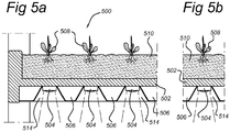
- FIGs. 5A and 5B show schematically cross-sections of a fourth embodiment of a tray according to the invention.
- Figure 5B is a cross section perpendicular to the cross section of Figure 5A .
- the tray comprises a top layer 502 of thermally conductive material.
- LEDs 504 are attached to the bottom side of the top layer 502. The heat generated by the LEDs 504 will be distributed across the top layer 502.
- a thermal isolation layer 506 is attached to the bottom side of the top layer 502. To pass the light emitted by the LEDs to the plant material below the tray 500, the isolation layer 506 comprises holes 514 at the position of the LEDs 504.
- the heat generated by the LEDs is mainly radiated via the upper surface of the tray to the substrate 510 to heat up the substrate 510.
- the holes 514 comprise collimators which shape the light beams of the LEDs.
- the heat pipes could be embedded in the top layer 502 of the fourth embodiment to improve the thermal conductivity of the top layer 502.
- the contact area of the top layer with the substrate could be increased by for example a wavelike surface instead of a flat surface or by providing cooling structures, for example ribs, to the top layer which extend the upper surface.
- the embodiments given above show trays with plant material. The invention could also be advantageously used in for example a laboratory for cultivating cell cultures or bacterial cultures.
Landscapes
- Life Sciences & Earth Sciences (AREA)
- Environmental Sciences (AREA)
- Biodiversity & Conservation Biology (AREA)
- Botany (AREA)
- Ecology (AREA)
- Forests & Forestry (AREA)
- Cultivation Of Plants (AREA)
- Cultivation Receptacles Or Flower-Pots, Or Pots For Seedlings (AREA)
Claims (12)
- Plateau (200) pour la croissance d'une matière organique comprenant une pluralité de LED (204), le plateau comportant un côté supérieur (202) et un côté inférieur (206), le côté supérieur étant agencé pour porter un substrat (210) pour la croissance d'une matière organique et le côté inférieur étant agencé pour faire rayonner la lumière générée par les LED, dans lequel le plateau comprend une structure permettant au plateau de faire rayonner plus de chaleur, générée par les LED, au côté supérieur qu'au côté inférieur du plateau.
- Plateau selon la revendication 1, dans lequel la structure comprend une première partie et une deuxième partie, un côté de la première partie formant le côté supérieur et un côté de la deuxième partie formant le côté inférieur du plateau, les LED étant attachées sur la première partie, qui a une conductivité thermique supérieure à celle de la deuxième partie.
- Plateau selon la revendication 2, dans lequel un espacement sépare la première partie et la deuxième partie.
- Plateau selon la revendication 2, dans lequel la matière de la première partie est au moins l'une des matières suivantes : métal, verre, plexiglas ou plastique.
- Plateau selon la revendication 2, dans lequel la matière de la deuxième partie est au moins l'une des matières transparentes ou diffusantes suivantes : verre, plexiglas ou plastique.
- Plateau selon la revendication 3, dans lequel la première partie au côté de l'espacement a une surface réfléchissante.
- Plateau selon l'une quelconque des revendication 1 à 6, dans lequel la structure comprend un ou plusieurs tuyaux de chaleur auxquels les LED sont thermiquement couplées.
- Plateau selon la revendication 7, dans lequel les tuyaux de chaleur sont positionnés horizontalement.
- Plateau selon la revendication 8, dans lequel les tuyaux de chaleur sont positionnés au-dessus d'une couche inférieure, la couche inférieure comprenant des zones pour permettre un passage de la lumière émise par les LED.
- Plateau selon la revendication 7, dans lequel les tuyaux de chaleur sont positionnés verticalement.
- Ensemble pépinière (100) comprenant une pluralité de plateaux (200) selon l'une quelconque des revendication 1 à 10, dans lequel les plateaux sont positionnés l'un au-dessus de l'autre.
- Procédé de croissance d'une matière organique, comprenant les étapes de :- la fourniture d'une zone pépinière contenant une matière organique dans un substrat avec des plateaux selon l'une quelconque des revendication 1 à 10, comprenant une pluralité de LED, et- la mise sous tension des LED de sorte qu'elles émettent une lumière sur ladite matière organique dans ledit substrat et chauffent le substrat par l'intermédiaire d'une structure desdits plateaux.
Priority Applications (1)
| Application Number | Priority Date | Filing Date | Title |
|---|---|---|---|
| EP08737782.6A EP2134155B1 (fr) | 2007-04-13 | 2008-04-10 | Plateau pour la croissance d'une matière organique et ensemble pépinière |
Applications Claiming Priority (3)
| Application Number | Priority Date | Filing Date | Title |
|---|---|---|---|
| EP07106169 | 2007-04-13 | ||
| PCT/IB2008/051354 WO2008126022A1 (fr) | 2007-04-13 | 2008-04-10 | Plateau pour la croissance d'une matière organique et ensemble pépinière |
| EP08737782.6A EP2134155B1 (fr) | 2007-04-13 | 2008-04-10 | Plateau pour la croissance d'une matière organique et ensemble pépinière |
Publications (2)
| Publication Number | Publication Date |
|---|---|
| EP2134155A1 EP2134155A1 (fr) | 2009-12-23 |
| EP2134155B1 true EP2134155B1 (fr) | 2017-03-01 |
Family
ID=39720089
Family Applications (1)
| Application Number | Title | Priority Date | Filing Date |
|---|---|---|---|
| EP08737782.6A Not-in-force EP2134155B1 (fr) | 2007-04-13 | 2008-04-10 | Plateau pour la croissance d'une matière organique et ensemble pépinière |
Country Status (5)
| Country | Link |
|---|---|
| US (1) | US20100115837A1 (fr) |
| EP (1) | EP2134155B1 (fr) |
| JP (1) | JP4932031B2 (fr) |
| CN (1) | CN101657089B (fr) |
| WO (1) | WO2008126022A1 (fr) |
Families Citing this family (27)
| Publication number | Priority date | Publication date | Assignee | Title |
|---|---|---|---|---|
| TWI454214B (zh) * | 2009-08-18 | 2014-10-01 | Noyu Corp | 霧耕栽培裝置 |
| JP5827460B2 (ja) * | 2010-09-07 | 2015-12-02 | 大成建設株式会社 | 照明装置および栽培システム |
| JP5283024B2 (ja) * | 2011-06-23 | 2013-09-04 | アメミヤ機器株式会社 | 植栽ベース |
| US9043962B2 (en) * | 2012-01-13 | 2015-06-02 | Danielle Trofe Design, Llc | Modular self-sustaining planter system |
| JP2015508636A (ja) * | 2012-01-30 | 2015-03-23 | バーティカル デザインズ リミテッドVertical Designs Ltd. | 自動化された園芸および農業のための方法および装置 |
| NL2008749C2 (nl) * | 2012-05-03 | 2013-11-06 | Vivi B V | Een samenstel, een kar en een container voor het kweken en/of groeien van planten. |
| RU2015105378A (ru) | 2012-07-18 | 2016-09-10 | Конинклейке Филипс Н.В. | Способ предоставления света для растениеводства сельскохозяйственной культуре и осветительное устройство для освещения для растениеводства |
| US20140069007A1 (en) * | 2012-09-13 | 2014-03-13 | Cashido Corporation | Plant growth facilitating apparatus plant growth facilitating apparatus |
| US20140318006A1 (en) * | 2013-04-26 | 2014-10-30 | Future Harvest Development Ltd. | Apparatus for lighting a mini greenhouse |
| JP6123495B2 (ja) * | 2013-05-31 | 2017-05-10 | 三菱樹脂アグリドリーム株式会社 | 多段棚式植物育成装置及び植物育成システム |
| KR20150000369A (ko) * | 2013-06-24 | 2015-01-02 | 한국전자통신연구원 | 식물공장에서의 조명 제어 장치 및 그 방법 |
| WO2015040785A1 (fr) * | 2013-09-19 | 2015-03-26 | パナソニックIpマネジメント株式会社 | Dispositif de culture de végétaux |
| US10842084B2 (en) | 2014-02-20 | 2020-11-24 | Affinor Growers Inc. | Vertical growing tower for automated horticulture and agriculture |
| CA2940062C (fr) | 2014-02-20 | 2022-05-03 | Affinor Growers Inc. | Procede et appareil d'horticulture et d'agriculture verticales automatisees |
| JP6199781B2 (ja) * | 2014-03-24 | 2017-09-20 | ヤンマー株式会社 | 移動栽培装置 |
| CN106413382B (zh) * | 2014-04-17 | 2020-04-17 | 万斯创新公司 | 适应于植物的光谱灵敏度的光源 |
| JP2018501800A (ja) * | 2014-12-30 | 2018-01-25 | スリーエム イノベイティブ プロパティズ カンパニー | 屋内園芸用の光熱管理システム |
| US9943042B2 (en) * | 2015-05-18 | 2018-04-17 | Biological Innovation & Optimization Systems, LLC | Grow light embodying power delivery and data communications features |
| US9951941B2 (en) * | 2015-11-02 | 2018-04-24 | Fluence Bioengineering | Light mounting systems and methods |
| JP6668060B2 (ja) * | 2015-12-03 | 2020-03-18 | 東京特殊電線株式会社 | 植物栽培用照明装置および植物栽培装置 |
| GB2548583B (en) * | 2016-03-22 | 2021-06-30 | Haygrove Ltd | Illumination arrangement |
| ITUA20164035A1 (it) * | 2016-06-01 | 2017-12-01 | Emanuel Colombini | Apparecchiatura modulare per colture, vegetali e animali, atta alla cura di aspetti psicologici e non, per mezzo di contenitori di illimtate forme interfacciabili tra di loro, autonomi e autorigeneranti, interfacciabili con sistemi di comunicazione e domotica, orizzontali, verticali, sospesi e microterrazze o dislivelli inclinati, sostenuta da packaging, con approvvigionamento di pezzi per mezzo di stampanti 3d, trasportabile in ogni spedizione terrestre, marina, sottomarina e spaziale, all'interno ed all'esterno di esercizi pubblici e privati. |
| US11622510B2 (en) | 2017-05-08 | 2023-04-11 | Urban Planter, Llc | Automated vertical plant cultivation system |
| US10524433B2 (en) * | 2017-05-08 | 2020-01-07 | Daniel S. Spiro | Automated vertical plant cultivation system |
| JP7020081B2 (ja) * | 2017-11-28 | 2022-02-16 | 株式会社竹中工務店 | 競技施設 |
| CA186505S (en) | 2019-03-06 | 2020-07-08 | Cobotix Mfg Inc | Agricultural and horticultural growing tower |
| WO2023038130A1 (fr) * | 2021-09-10 | 2023-03-16 | 株式会社プランテックス | Plateau de solution nutritive |
Family Cites Families (22)
| Publication number | Priority date | Publication date | Assignee | Title |
|---|---|---|---|---|
| US2051461A (en) * | 1934-06-02 | 1936-08-18 | Alfred Wallace Wallace Turner | Apparatus for raising plants from seed |
| US3314192A (en) * | 1964-06-01 | 1967-04-18 | Park George Barratt | Plant growing shelf arrangement |
| JPS61119121A (ja) * | 1984-11-14 | 1986-06-06 | 松下電工株式会社 | 草花育成用家具 |
| JPH0427310Y2 (fr) * | 1986-09-25 | 1992-06-30 | ||
| NL185889C (nl) * | 1987-09-16 | 1990-08-16 | Nijssen Light Div | Werkwijze voor het belichten van zaad of plant. |
| US5012609A (en) * | 1988-12-12 | 1991-05-07 | Automated Agriculture Associates, Inc. | Method and apparatus for irradiation of plants using optoelectronic devices |
| JPH02283219A (ja) * | 1989-04-25 | 1990-11-20 | Shimizu Corp | 植物栽培装置 |
| JP3952220B2 (ja) * | 1996-11-06 | 2007-08-01 | 金原 士朗 | 栽培棚 |
| JP3105482B2 (ja) * | 1997-10-15 | 2000-10-30 | 株式会社テクノバ | 育苗装置 |
| TW421993U (en) * | 2000-05-30 | 2001-02-11 | Wei Fang | Plant cultivation box using ultra-bright LED as artificial light source |
| US6554450B2 (en) * | 2001-04-19 | 2003-04-29 | Wei Fang | Artificial lighting apparatus for young plants using light emitting diodes as light source |
| JP2003079254A (ja) * | 2001-07-05 | 2003-03-18 | Ccs Inc | 植物育成装置およびその制御システム |
| US6680200B2 (en) * | 2002-02-22 | 2004-01-20 | Biolex, Inc. | Led array for illuminating cell well plates and automated rack system for handling the same |
| EP1543718B1 (fr) * | 2002-09-20 | 2007-07-11 | Taiyo Kogyo Co., Ltd. | Systeme de culture de semis |
| JP2004194631A (ja) * | 2002-12-13 | 2004-07-15 | Susumu Iwasaki | 照明付植木鉢及び鉢受け皿 |
| US7033060B2 (en) * | 2003-05-23 | 2006-04-25 | Gelcore Llc | Method and apparatus for irradiation of plants using light emitting diodes |
| WO2005000005A1 (fr) * | 2003-06-27 | 2005-01-06 | Taiyo Kogyo Co., Ltd. | Dispositif et procede de culture de semis |
| CN1233217C (zh) * | 2003-09-02 | 2005-12-28 | 中国科学院上海生命科学研究院 | 一种植物根系光照装置及其方法 |
| TW200513174A (en) * | 2003-09-03 | 2005-04-16 | Tdk Corp | Method and system for gill fungus, culturing frame, method for culturing glossy ganoderma, culturing system |
| JP4265427B2 (ja) * | 2004-02-04 | 2009-05-20 | 市光工業株式会社 | 車両用灯具 |
| JP2006047914A (ja) * | 2004-08-09 | 2006-02-16 | Seiko Epson Corp | プロジェクタ |
| US7472513B2 (en) * | 2006-01-12 | 2009-01-06 | Cets, Llc | Controlled environment system and method for rapid propagation of seed potato stocks |
-
2008
- 2008-04-10 EP EP08737782.6A patent/EP2134155B1/fr not_active Not-in-force
- 2008-04-10 US US12/594,838 patent/US20100115837A1/en not_active Abandoned
- 2008-04-10 WO PCT/IB2008/051354 patent/WO2008126022A1/fr not_active Ceased
- 2008-04-10 CN CN2008800118970A patent/CN101657089B/zh not_active Expired - Fee Related
- 2008-04-10 JP JP2010502624A patent/JP4932031B2/ja not_active Expired - Fee Related
Non-Patent Citations (1)
| Title |
|---|
| None * |
Also Published As
| Publication number | Publication date |
|---|---|
| JP4932031B2 (ja) | 2012-05-16 |
| WO2008126022A1 (fr) | 2008-10-23 |
| JP2010523140A (ja) | 2010-07-15 |
| CN101657089B (zh) | 2012-11-14 |
| US20100115837A1 (en) | 2010-05-13 |
| CN101657089A (zh) | 2010-02-24 |
| EP2134155A1 (fr) | 2009-12-23 |
Similar Documents
| Publication | Publication Date | Title |
|---|---|---|
| EP2134155B1 (fr) | Plateau pour la croissance d'une matière organique et ensemble pépinière | |
| EP2076113B1 (fr) | Dispositif permettant la croissance de plantes | |
| US8523385B2 (en) | Compact high brightness LED grow light apparatus, using an extended point source LED array with light emitting diodes | |
| US20160360712A1 (en) | Grow lighting and agricultural systems and methods | |
| US20190141923A1 (en) | Apparatus and methods for a hydroponics system with enhanced heat transfer | |
| CN204141364U (zh) | Led照明管以及植物栽培用照明装置 | |
| EP2893255B1 (fr) | Appareil d'éclairage avec lentille de dissipation de chaleur intégrée | |
| CN104981147A (zh) | 照明系统及植物栽培装置 | |
| JP2018019667A (ja) | 照明システム、照明制御方法及び植物栽培器 | |
| KR101279050B1 (ko) | 엘이디 조명이 구비된 수경재배기 | |
| JP7120838B2 (ja) | 発光装置および照明装置 | |
| JP6401047B2 (ja) | 光合成促進光源 | |
| EP2757601B1 (fr) | Appareil émetteur de lumière et appareil d'éclairage pourvu de cet appareil émetteur de lumière | |
| JP2019194983A (ja) | 照明装置、照明モジュールおよび照明システム | |
| JP5653764B2 (ja) | 植物栽培用の照明装置および植物栽培装置 | |
| KR20110087814A (ko) | 원적외선을 방사하는 생육장치 | |
| KR101234015B1 (ko) | 다층배지용 조명장치 | |
| WO2019164014A1 (fr) | Dispositif électroluminescent et appareil d'éclairage | |
| JP2019175926A (ja) | 発光装置および照明装置 | |
| GB2566247A (en) | A lighting apparatus | |
| US12137649B2 (en) | Greenhouse luminaire with minimal daylight interception | |
| JP2019129245A (ja) | 発光装置および照明装置 | |
| JP5394583B2 (ja) | 発光装置、および発光装置を備えた光照射装置 | |
| KR101486360B1 (ko) | 비닐하우스용 전기난방장치 |
Legal Events
| Date | Code | Title | Description |
|---|---|---|---|
| PUAI | Public reference made under article 153(3) epc to a published international application that has entered the european phase |
Free format text: ORIGINAL CODE: 0009012 |
|
| 17P | Request for examination filed |
Effective date: 20091113 |
|
| AK | Designated contracting states |
Kind code of ref document: A1 Designated state(s): AT BE BG CH CY CZ DE DK EE ES FI FR GB GR HR HU IE IS IT LI LT LU LV MC MT NL NO PL PT RO SE SI SK TR |
|
| DAX | Request for extension of the european patent (deleted) | ||
| RAP1 | Party data changed (applicant data changed or rights of an application transferred) |
Owner name: KONINKLIJKE PHILIPS N.V. |
|
| RAP1 | Party data changed (applicant data changed or rights of an application transferred) |
Owner name: PHILIPS LIGHTING HOLDING B.V. |
|
| GRAP | Despatch of communication of intention to grant a patent |
Free format text: ORIGINAL CODE: EPIDOSNIGR1 |
|
| INTG | Intention to grant announced |
Effective date: 20160923 |
|
| GRAS | Grant fee paid |
Free format text: ORIGINAL CODE: EPIDOSNIGR3 |
|
| GRAA | (expected) grant |
Free format text: ORIGINAL CODE: 0009210 |
|
| AK | Designated contracting states |
Kind code of ref document: B1 Designated state(s): AT BE BG CH CY CZ DE DK EE ES FI FR GB GR HR HU IE IS IT LI LT LU LV MC MT NL NO PL PT RO SE SI SK TR |
|
| REG | Reference to a national code |
Ref country code: GB Ref legal event code: FG4D |
|
| REG | Reference to a national code |
Ref country code: CH Ref legal event code: EP Ref country code: AT Ref legal event code: REF Ref document number: 870201 Country of ref document: AT Kind code of ref document: T Effective date: 20170315 |
|
| REG | Reference to a national code |
Ref country code: IE Ref legal event code: FG4D |
|
| REG | Reference to a national code |
Ref country code: DE Ref legal event code: R096 Ref document number: 602008048933 Country of ref document: DE |
|
| REG | Reference to a national code |
Ref country code: FR Ref legal event code: PLFP Year of fee payment: 10 |
|
| REG | Reference to a national code |
Ref country code: NL Ref legal event code: FP |
|
| REG | Reference to a national code |
Ref country code: LT Ref legal event code: MG4D |
|
| REG | Reference to a national code |
Ref country code: AT Ref legal event code: MK05 Ref document number: 870201 Country of ref document: AT Kind code of ref document: T Effective date: 20170301 |
|
| RIN2 | Information on inventor provided after grant (corrected) |
Inventor name: RAAIJMAKERS, ANTONIUS, H., M. Inventor name: VAN DER POEL, LUCAS, L., D. |
|
| PG25 | Lapsed in a contracting state [announced via postgrant information from national office to epo] |
Ref country code: FI Free format text: LAPSE BECAUSE OF FAILURE TO SUBMIT A TRANSLATION OF THE DESCRIPTION OR TO PAY THE FEE WITHIN THE PRESCRIBED TIME-LIMIT Effective date: 20170301 Ref country code: HR Free format text: LAPSE BECAUSE OF FAILURE TO SUBMIT A TRANSLATION OF THE DESCRIPTION OR TO PAY THE FEE WITHIN THE PRESCRIBED TIME-LIMIT Effective date: 20170301 Ref country code: GR Free format text: LAPSE BECAUSE OF FAILURE TO SUBMIT A TRANSLATION OF THE DESCRIPTION OR TO PAY THE FEE WITHIN THE PRESCRIBED TIME-LIMIT Effective date: 20170602 Ref country code: LT Free format text: LAPSE BECAUSE OF FAILURE TO SUBMIT A TRANSLATION OF THE DESCRIPTION OR TO PAY THE FEE WITHIN THE PRESCRIBED TIME-LIMIT Effective date: 20170301 Ref country code: NO Free format text: LAPSE BECAUSE OF FAILURE TO SUBMIT A TRANSLATION OF THE DESCRIPTION OR TO PAY THE FEE WITHIN THE PRESCRIBED TIME-LIMIT Effective date: 20170601 |
|
| PG25 | Lapsed in a contracting state [announced via postgrant information from national office to epo] |
Ref country code: LV Free format text: LAPSE BECAUSE OF FAILURE TO SUBMIT A TRANSLATION OF THE DESCRIPTION OR TO PAY THE FEE WITHIN THE PRESCRIBED TIME-LIMIT Effective date: 20170301 Ref country code: SE Free format text: LAPSE BECAUSE OF FAILURE TO SUBMIT A TRANSLATION OF THE DESCRIPTION OR TO PAY THE FEE WITHIN THE PRESCRIBED TIME-LIMIT Effective date: 20170301 Ref country code: ES Free format text: LAPSE BECAUSE OF FAILURE TO SUBMIT A TRANSLATION OF THE DESCRIPTION OR TO PAY THE FEE WITHIN THE PRESCRIBED TIME-LIMIT Effective date: 20170301 Ref country code: AT Free format text: LAPSE BECAUSE OF FAILURE TO SUBMIT A TRANSLATION OF THE DESCRIPTION OR TO PAY THE FEE WITHIN THE PRESCRIBED TIME-LIMIT Effective date: 20170301 Ref country code: BG Free format text: LAPSE BECAUSE OF FAILURE TO SUBMIT A TRANSLATION OF THE DESCRIPTION OR TO PAY THE FEE WITHIN THE PRESCRIBED TIME-LIMIT Effective date: 20170601 |
|
| PG25 | Lapsed in a contracting state [announced via postgrant information from national office to epo] |
Ref country code: RO Free format text: LAPSE BECAUSE OF FAILURE TO SUBMIT A TRANSLATION OF THE DESCRIPTION OR TO PAY THE FEE WITHIN THE PRESCRIBED TIME-LIMIT Effective date: 20170301 Ref country code: SK Free format text: LAPSE BECAUSE OF FAILURE TO SUBMIT A TRANSLATION OF THE DESCRIPTION OR TO PAY THE FEE WITHIN THE PRESCRIBED TIME-LIMIT Effective date: 20170301 Ref country code: IT Free format text: LAPSE BECAUSE OF FAILURE TO SUBMIT A TRANSLATION OF THE DESCRIPTION OR TO PAY THE FEE WITHIN THE PRESCRIBED TIME-LIMIT Effective date: 20170301 Ref country code: CZ Free format text: LAPSE BECAUSE OF FAILURE TO SUBMIT A TRANSLATION OF THE DESCRIPTION OR TO PAY THE FEE WITHIN THE PRESCRIBED TIME-LIMIT Effective date: 20170301 Ref country code: EE Free format text: LAPSE BECAUSE OF FAILURE TO SUBMIT A TRANSLATION OF THE DESCRIPTION OR TO PAY THE FEE WITHIN THE PRESCRIBED TIME-LIMIT Effective date: 20170301 |
|
| PG25 | Lapsed in a contracting state [announced via postgrant information from national office to epo] |
Ref country code: PT Free format text: LAPSE BECAUSE OF FAILURE TO SUBMIT A TRANSLATION OF THE DESCRIPTION OR TO PAY THE FEE WITHIN THE PRESCRIBED TIME-LIMIT Effective date: 20170703 Ref country code: IS Free format text: LAPSE BECAUSE OF FAILURE TO SUBMIT A TRANSLATION OF THE DESCRIPTION OR TO PAY THE FEE WITHIN THE PRESCRIBED TIME-LIMIT Effective date: 20170701 Ref country code: PL Free format text: LAPSE BECAUSE OF FAILURE TO SUBMIT A TRANSLATION OF THE DESCRIPTION OR TO PAY THE FEE WITHIN THE PRESCRIBED TIME-LIMIT Effective date: 20170301 |
|
| REG | Reference to a national code |
Ref country code: CH Ref legal event code: PL |
|
| REG | Reference to a national code |
Ref country code: DE Ref legal event code: R097 Ref document number: 602008048933 Country of ref document: DE |
|
| PLBE | No opposition filed within time limit |
Free format text: ORIGINAL CODE: 0009261 |
|
| STAA | Information on the status of an ep patent application or granted ep patent |
Free format text: STATUS: NO OPPOSITION FILED WITHIN TIME LIMIT |
|
| REG | Reference to a national code |
Ref country code: IE Ref legal event code: MM4A |
|
| PG25 | Lapsed in a contracting state [announced via postgrant information from national office to epo] |
Ref country code: DK Free format text: LAPSE BECAUSE OF FAILURE TO SUBMIT A TRANSLATION OF THE DESCRIPTION OR TO PAY THE FEE WITHIN THE PRESCRIBED TIME-LIMIT Effective date: 20170301 Ref country code: MC Free format text: LAPSE BECAUSE OF FAILURE TO SUBMIT A TRANSLATION OF THE DESCRIPTION OR TO PAY THE FEE WITHIN THE PRESCRIBED TIME-LIMIT Effective date: 20170301 |
|
| 26N | No opposition filed |
Effective date: 20171204 |
|
| PG25 | Lapsed in a contracting state [announced via postgrant information from national office to epo] |
Ref country code: LU Free format text: LAPSE BECAUSE OF NON-PAYMENT OF DUE FEES Effective date: 20170410 Ref country code: SI Free format text: LAPSE BECAUSE OF FAILURE TO SUBMIT A TRANSLATION OF THE DESCRIPTION OR TO PAY THE FEE WITHIN THE PRESCRIBED TIME-LIMIT Effective date: 20170301 Ref country code: CH Free format text: LAPSE BECAUSE OF NON-PAYMENT OF DUE FEES Effective date: 20170430 Ref country code: LI Free format text: LAPSE BECAUSE OF NON-PAYMENT OF DUE FEES Effective date: 20170430 |
|
| REG | Reference to a national code |
Ref country code: BE Ref legal event code: MM Effective date: 20170430 |
|
| REG | Reference to a national code |
Ref country code: FR Ref legal event code: PLFP Year of fee payment: 11 |
|
| PG25 | Lapsed in a contracting state [announced via postgrant information from national office to epo] |
Ref country code: IE Free format text: LAPSE BECAUSE OF NON-PAYMENT OF DUE FEES Effective date: 20170410 |
|
| PG25 | Lapsed in a contracting state [announced via postgrant information from national office to epo] |
Ref country code: BE Free format text: LAPSE BECAUSE OF NON-PAYMENT OF DUE FEES Effective date: 20170430 |
|
| PG25 | Lapsed in a contracting state [announced via postgrant information from national office to epo] |
Ref country code: MT Free format text: LAPSE BECAUSE OF NON-PAYMENT OF DUE FEES Effective date: 20170410 |
|
| PG25 | Lapsed in a contracting state [announced via postgrant information from national office to epo] |
Ref country code: HU Free format text: LAPSE BECAUSE OF FAILURE TO SUBMIT A TRANSLATION OF THE DESCRIPTION OR TO PAY THE FEE WITHIN THE PRESCRIBED TIME-LIMIT; INVALID AB INITIO Effective date: 20080410 |
|
| PG25 | Lapsed in a contracting state [announced via postgrant information from national office to epo] |
Ref country code: CY Free format text: LAPSE BECAUSE OF NON-PAYMENT OF DUE FEES Effective date: 20170301 |
|
| REG | Reference to a national code |
Ref country code: NL Ref legal event code: HC Owner name: SIGNIFY HOLDING B.V.; NL Free format text: DETAILS ASSIGNMENT: CHANGE OF OWNER(S), CHANGE OF OWNER(S) NAME; FORMER OWNER NAME: PHILIPS LIGHTING HOLDING B.V. Effective date: 20200304 |
|
| PG25 | Lapsed in a contracting state [announced via postgrant information from national office to epo] |
Ref country code: TR Free format text: LAPSE BECAUSE OF FAILURE TO SUBMIT A TRANSLATION OF THE DESCRIPTION OR TO PAY THE FEE WITHIN THE PRESCRIBED TIME-LIMIT Effective date: 20170301 |
|
| PGFP | Annual fee paid to national office [announced via postgrant information from national office to epo] |
Ref country code: FR Payment date: 20200429 Year of fee payment: 13 Ref country code: DE Payment date: 20200430 Year of fee payment: 13 Ref country code: NL Payment date: 20200428 Year of fee payment: 13 |
|
| PGFP | Annual fee paid to national office [announced via postgrant information from national office to epo] |
Ref country code: GB Payment date: 20200429 Year of fee payment: 13 |
|
| REG | Reference to a national code |
Ref country code: DE Ref legal event code: R119 Ref document number: 602008048933 Country of ref document: DE |
|
| REG | Reference to a national code |
Ref country code: NL Ref legal event code: MM Effective date: 20210501 |
|
| GBPC | Gb: european patent ceased through non-payment of renewal fee |
Effective date: 20210410 |
|
| PG25 | Lapsed in a contracting state [announced via postgrant information from national office to epo] |
Ref country code: DE Free format text: LAPSE BECAUSE OF NON-PAYMENT OF DUE FEES Effective date: 20211103 Ref country code: FR Free format text: LAPSE BECAUSE OF NON-PAYMENT OF DUE FEES Effective date: 20210430 Ref country code: GB Free format text: LAPSE BECAUSE OF NON-PAYMENT OF DUE FEES Effective date: 20210410 |
|
| PG25 | Lapsed in a contracting state [announced via postgrant information from national office to epo] |
Ref country code: NL Free format text: LAPSE BECAUSE OF NON-PAYMENT OF DUE FEES Effective date: 20210501 |