EP2134623B1 - Récipient destiné à contenir un liquide et ensemble de récipient et d'orifice de sortie - Google Patents
Récipient destiné à contenir un liquide et ensemble de récipient et d'orifice de sortie Download PDFInfo
- Publication number
- EP2134623B1 EP2134623B1 EP08717698.8A EP08717698A EP2134623B1 EP 2134623 B1 EP2134623 B1 EP 2134623B1 EP 08717698 A EP08717698 A EP 08717698A EP 2134623 B1 EP2134623 B1 EP 2134623B1
- Authority
- EP
- European Patent Office
- Prior art keywords
- container
- fluid
- outlet
- moveable element
- chamber
- Prior art date
- Legal status (The legal status is an assumption and is not a legal conclusion. Google has not performed a legal analysis and makes no representation as to the accuracy of the status listed.)
- Not-in-force
Links
- 239000012530 fluid Substances 0.000 title claims description 159
- 230000000903 blocking effect Effects 0.000 claims description 31
- 239000004033 plastic Substances 0.000 claims description 3
- 238000005452 bending Methods 0.000 claims description 2
- 239000000463 material Substances 0.000 description 4
- 238000007789 sealing Methods 0.000 description 4
- 238000004891 communication Methods 0.000 description 3
- 230000005484 gravity Effects 0.000 description 3
- 229920006362 Teflon® Polymers 0.000 description 1
- 238000010276 construction Methods 0.000 description 1
- 238000010790 dilution Methods 0.000 description 1
- 239000012895 dilution Substances 0.000 description 1
- 230000000694 effects Effects 0.000 description 1
- 239000008269 hand cream Substances 0.000 description 1
- 230000001788 irregular Effects 0.000 description 1
- 238000004519 manufacturing process Methods 0.000 description 1
- 239000002184 metal Substances 0.000 description 1
- 239000000203 mixture Substances 0.000 description 1
- 238000000926 separation method Methods 0.000 description 1
- 239000007787 solid Substances 0.000 description 1
- 238000011144 upstream manufacturing Methods 0.000 description 1
Images



Classifications
-
- B—PERFORMING OPERATIONS; TRANSPORTING
- B65—CONVEYING; PACKING; STORING; HANDLING THIN OR FILAMENTARY MATERIAL
- B65D—CONTAINERS FOR STORAGE OR TRANSPORT OF ARTICLES OR MATERIALS, e.g. BAGS, BARRELS, BOTTLES, BOXES, CANS, CARTONS, CRATES, DRUMS, JARS, TANKS, HOPPERS, FORWARDING CONTAINERS; ACCESSORIES, CLOSURES, OR FITTINGS THEREFOR; PACKAGING ELEMENTS; PACKAGES
- B65D83/00—Containers or packages with special means for dispensing contents
- B65D83/14—Containers for dispensing liquid or semi-liquid contents by internal gaseous pressure, i.e. aerosol containers comprising propellant
- B65D83/44—Valves specially adapted for the discharge of contents; Regulating devices
-
- B—PERFORMING OPERATIONS; TRANSPORTING
- B65—CONVEYING; PACKING; STORING; HANDLING THIN OR FILAMENTARY MATERIAL
- B65D—CONTAINERS FOR STORAGE OR TRANSPORT OF ARTICLES OR MATERIALS, e.g. BAGS, BARRELS, BOTTLES, BOXES, CANS, CARTONS, CRATES, DRUMS, JARS, TANKS, HOPPERS, FORWARDING CONTAINERS; ACCESSORIES, CLOSURES, OR FITTINGS THEREFOR; PACKAGING ELEMENTS; PACKAGES
- B65D83/00—Containers or packages with special means for dispensing contents
- B65D83/14—Containers for dispensing liquid or semi-liquid contents by internal gaseous pressure, i.e. aerosol containers comprising propellant
- B65D83/42—Filling or charging means
- B65D83/425—Delivery valves permitting filling or charging
-
- B—PERFORMING OPERATIONS; TRANSPORTING
- B65—CONVEYING; PACKING; STORING; HANDLING THIN OR FILAMENTARY MATERIAL
- B65D—CONTAINERS FOR STORAGE OR TRANSPORT OF ARTICLES OR MATERIALS, e.g. BAGS, BARRELS, BOTTLES, BOXES, CANS, CARTONS, CRATES, DRUMS, JARS, TANKS, HOPPERS, FORWARDING CONTAINERS; ACCESSORIES, CLOSURES, OR FITTINGS THEREFOR; PACKAGING ELEMENTS; PACKAGES
- B65D83/00—Containers or packages with special means for dispensing contents
- B65D83/14—Containers for dispensing liquid or semi-liquid contents by internal gaseous pressure, i.e. aerosol containers comprising propellant
- B65D83/60—Containers for dispensing liquid or semi-liquid contents by internal gaseous pressure, i.e. aerosol containers comprising propellant with contents and propellant separated
- B65D83/64—Containers for dispensing liquid or semi-liquid contents by internal gaseous pressure, i.e. aerosol containers comprising propellant with contents and propellant separated by pistons
- B65D83/646—Containers for dispensing liquid or semi-liquid contents by internal gaseous pressure, i.e. aerosol containers comprising propellant with contents and propellant separated by pistons the piston being provided with a dispensing opening through which the contents are dispensed
Definitions
- the application is related to a container for holding a fluid comprising: a fluid chamber having an inner wall; an outlet-opening; and a high pressure chamber for driving the fluid towards the outlet-opening.
- the invention is further related to an assembly of such a container and an outlet adapted for connection to the container for releasing the fluid from the fluid chamber.
- the invention is further related to a container for holding a viscous fluid comprising a fluid chamber having an outlet opening; and a high pressure chamber for driving the fluid towards the outlet-opening.
- a container for holding a fluid is for instance known from WO 01/09009 A1 which shows a container that in use holds a fluid comprising both a pressurized driving gas and a product fluid which is meant to be dispensed.
- a container is also known form Belgian patent BE 864447 .
- United States patents US 6230943 , US 3099370 , French patent FR 2295345 and German patent application publication DE 19632329 disclose further prior art examples of containers for the dispensing of products.
- Certain fluid products to be dispensed are however not to be intermixed with a pressurized driving gas.
- intermixing may not only imply a dilution of the fluid to be dispensed but may sometimes also be harmful.
- gas pockets in a denser fluid product are in general undesired. This is related to the fact that viscosity, density and surface tension are all properties which often differ enormously between a pressurized gas and a dense or viscous fluid to be dispensed.
- pockets of pressurized gas are present in the product fluid the dispensing dynamics change, resulting in unpredictable and/or irregular dispensing behaviour.
- Both WO 2004/065217 A2 and WO 2004/065261 A1 disclose a fluid dispensing system showing a product chamber for holding the fluid to be dispensed and a high pressure chamber as well as a working pressure chamber for providing a more or less constant working pressure on the fluid to be dispensed.
- the chambers in which pressurized gas is held i.e. the high pressure chamber and the working pressure chamber, are separated from the product chamber.
- the working pressure chamber increases in volume at the expense of the volume of the product chamber, as such keeping up the working pressure on the product.
- the expansion of the working pressure chamber occurs within the product chamber in such a way that certain volume parts of the product fluid are not satisfactorily driven out of the product chamber when the product fluid is to be dispensed.
- WO 99/62791 discloses a container for holding a fluid wherein a volume of the chamber in which the product is held, can be reduced by moving a piston-like element in the direction of the product chamber. Such a construction restricts the window of design parameters, forcing a designer to work almost exclusively with a piston and cylinder-like arrangement, also known as a cylindrical arrangement.
- Design of a container for holding a dispensable fluid is however not only restricted by constructional constraints or constraints related to the dispensing of the fluid. Problems which need to be solved for obtaining a commercially viable container are also related to the fabrication of the container and are related to both the filling of the container with the fluid to be dispensed and the application of a high pressure chamber for driving the fluid out of the container.
- the fluid chamber remains fully separated from the high pressure chamber and it thus holds that the fluid to be dispensed remains separated from high pressurized gas in cases where such a gas is employed for driving the fluid towards the outlet.
- This effect will remain present, independent from a change of cross sectional dimensions of the container at different positions along the predetermined direction.
- the container does not necessarily have to be cylindrical in shape having its axis parallel to the predetermined direction to drive most if not all the dispensable fluid out of the container and/or to maintain complete separation of driving gas and fluid to be dispensed.
- This embodiment allows for a higher flexibility in design of the fluid chamber and the container as a whole, and allows thus for a more fanciful design of, for instance, a bottle of hand cream with a dispensing mechanism.
- this embodiment of a container also reduces the likelihood of fluid remaining unused in the container after dispensing the fluid.
- an upright position of the container In an upright position of the container is the first position above the second position. In the upright position, the container will maintain a very stable position given that the fluid with the higher density, i.e. the fluid to be dispensed, remains positioned at the lower end of the container even when a part of that fluid has already been dispensed. Further, when in use the container is in the upright position and a pressurized gas is used in the high pressure chamber, the high pressurized gas will not diffuse into the viscous fluid to be dispensed as in this orientation of the container the fluid to be dispensed is below the high pressure chamber. Gas pockets will consequently not be formed. The interface between the high pressurized gas and the fluid to be dispensed is unlikely to offer positions at which the high pressurized gas can easily mix with the fluid to be dispensed, given that in use the moveable element presses downwards onto the fluid product.
- the fluid path for releasing fluid from the fluid chamber can be blocked, it is possible to avoid a gas entering the fluid chamber from a position downstream the fluid path for releasing fluid from the fluid chamber.
- This allows for using a downstream part of the fluid path for filling the high pressure chamber whilst keeping the design of the outlet simple.
- the container and the outlet are in a simple way suitable for both dispensing the fluid from the fluid chamber and filling the high pressure chamber with gas.
- Fig. 1 shows an embodiment of a container 1 for holding a fluid.
- the container 1 comprises a fluid chamber 2 having an inner wall 3.
- the container 1 further comprises an outlet-opening which in Fig. 1 is situated at an upper part of the container 1 and for reasons of clarity not indicated by a reference number as the opening itself is incorporated in a part which will be discussed later. It will later be discussed how this outlet-opening communicates for instance with the fluid chamber 2.
- the container further comprises a high pressure chamber 4 for driving the fluid towards the outlet-opening.
- the container 1 further comprises as at least part of a divider between the high pressure chamber 4 and the fluid chamber 2 a moveable element 5 for advancing in a predetermined direction of motion, indicated by arrow A, through the container 1, from a first position, as shown in Fig. 1 by solid lines, to a second position, as schematically shown by dashed lines.
- the first and second position of the moveable elements are arbitrarily taken as positions where the moveable element 5 has contact with the inner wall 3.
- a volume of the fluid chamber 2 is reduced. As will be explained later, this will happen when fluid is dispensed via the outlet opening.
- a first cross section, indicated by the line I-I, taken transverse the direction of motion at the first position of the moveable element 5, has a dimension which is different from a second cross section of the fluid chamber 2, indicated by the line II-II, at the second position.
- the moveable element 5 is a resilient element which is biased towards expanding in directions transverse, indicated by arrow T, relative to the predetermined direction, indicated by arrow A.
- a tight contact between the moveable element 5 and the inner wall 3 of the container 1 is as a result of this bias as maintained, also during movement of the moveable element 5 from the first to the second position.
- the predetermined direction is downwards.
- the upright position is the position in which the container is placed when put away for instance on a shelf when not in active use.
- the container is usually provided in a shape so that it is immediately clear to a user which position of the container can be used as the upright position. It follows that in the upright position, the first position is above the second position.
- the centre of gravity of the fluid moves downward as the relatively heavy fluid is being dispensed from the fluid chamber 2. As the centre of gravity of the residual fluid will move toward a bottom 6 of the container 1, stability of the container 1 is optimized even though very little fluid may be left in container 1.
- the first and second cross section of the fluid chamber 2, taken transverse the direction of motion, have different dimensions at respectively the first and second position.
- Moveable element 5 is a resilient element which is biased towards expanding in directions transverse the predetermined direction, i.e. biased in a direction T transverse a direction A.
- the embodiment shown in Fig. 1 is such that tight contact between the element 5 and inner wall 3 of the container 1 is maintained during the movement of the moveable element 5 from the first to the second position.
- the moveable element 5 is moveable in its entirety. However, it is not inconceivable that parts of the moveable element are fixed with respect to the inner wall 3 of the container 1.
- Fig. 1 shows an embodiment in which the predetermined direction is downward when the container is in an upright position
- the predetermined position can also be chosen to be upward when the container is in an upright position.
- any direction can be chosen as the predetermined direction for reducing a volume of the fluid chamber.
- the advantage of the optimized continuing stability as present when the predetermined direction is downward may in certain cases not be relevant. It is of course also possible to make the bottom of the container heavy so that stability is also guaranteed with a predetermined direction different from downward.
- the moveable element 5 comprises an impermeable wall between the fluid chamber 2 and a high pressure chamber 4. With an impermeable wall gas exchange between the fluid chamber and the high pressure chamber is drastically minimized if not fully excluded.
- the moveable element 5 may have a concave side facing the high pressure chamber 4.
- the moveable element 5 may have a convex side facing the fluid chamber 2. This also allows for a very simple embodiment of moveable element 5.
- the moveable element 5 comprises a rubber or an elastic plastic. It is further possible that the moveable element 5 is made of for instance PET.
- the moveable element 5 may be biased by the bending outer portions 7 of the resilient member towards the high pressure chamber 4.
- the moveable element 5 may be provided with a relatively stiff ring 8(not shown in Fig. 1 ) for obtaining a relatively stiff part of the moveable element within the ring and a relatively flexible part outside the ring.
- the moveable element 5 may have at outer part 9 which maintains contact with the inner wall 3 of the container 1, a flexibility which is higher than the flexibility at an inner part 10 which is free from contact with the inner wall 3 of the container 1.
- the container may have rotational symmetry with respect to the predetermined direction A.
- the container is shaped such that at each next position which the moveable element 5 reaches when advancing in the predetermined direction A, the transverse cross section of the container 1 is larger than the cross section at a previous position.
- the pressure in the high pressure chamber may reduce due to increase of its volume, it is advantageous to have the cross sectional dimensions of the container larger at following positions of the moveable element, as this means lesser friction between moveable element 5 and inner wall 3. This in turn means that advancement of the moveable element is still possible despite the lower "driving force" provided by the high pressure chamber 4.
- the container may comprise a guiding member 11 for guiding movement of the moveable element 5 in the predetermined direction A.
- the moveable element 5 and the guiding member 11 are, in this example, coaxially arranged within the container 1.
- the guiding member 11 is hollow and arranged for transport of the fluid from the fluid chamber 2 towards the outlet-opening.
- the outlet-opening is arranged at the top of the container 1. However, at the outlet-opening an outlet 12 is situated in a way and for a reason further described when discussing Fig. 4 .
- flow direction will be used for describing relative positions. This direction corresponds to the direction of the flow of the fluid to be dispensed. Relative positions are indicated by either “upstream” or “downstream”.
- a pressure control device 13 Downstream the outlet 12 is a pressure control device 13 situated for dispensing the fluid within a predetermined range of pressure.
- Fig. 1 Before moving on to a description of the other figures, it is to be noted from Fig. 1 that when the moveable element 5 advances in the predetermined direction A, the volume of the fluid chamber 2 reduces, which is possible as the fluid can move via an entrance 14 in the hollow guiding member 11 towards the outlet 12.
- the entrance 14 of the hollow guiding member 11 is situated near a bottom 6 of the container 1. It will be clear that it is also possible to have the guiding member 11 solid, and to have another channel for flow of fluid from the fluid chamber to the outlet 12. It is also possible to have the outlet-opening and outlet 12 directly in the fluid chamber.
- the high pressure chamber holds a gas having a pressure high enough to move at least part of the moveable element 5 when fluid is dispensed so that fluid is driven towards the outlet 12 via the hollow guiding member 11.
- highly pressurized gas is preferably used, it is not inconceivable that the high pressure chamber is capable of providing a high pressure onto the moveable element due to, for instance, a spring present in the high pressure chamber 4.
- Fig. 2 shows moveable element 5 of an embodiment of a container 1 in accordance with an aspect of the invention.
- This embodiment of a moveable element 5 comprises a sheet or film 15 as in use clamped between a clamping assembly comprising a male part 16 and a female part 17.
- the moveable element 5 may also comprise a ring 8 as earlier discussed.
- the film 15 may be of a flexible material such as PET or a thin rubber material.
- Ring 8 will be of a material that is stiff relative to the film 15 and also the clamping assembly with male and female parts 16, 17 may be of a relatively stiff plastic.
- An inner wall 19 and 20 of respectively male and female part 16 and 17 has preferably a low friction surface and may for instance be coated with a Teflon® layer to facilitate sliding along the guiding member 11.
- Fig. 3 shows schematically in an exploded view details of an outlet of an embodiment of the invention.
- the corresponding parts are also shown in Fig. 1 as assembled into an outlet 12 which is placed in the outlet opening.
- Fig. 3 shows respectively an outer mounting cup 21, a stem holder cup 22, an O-ring 23, a stem holder 24, a stem 25, a spring 26, a spring holder 27, and an inner clampable stop 28.
- Stem 25 comprises an outlet channel 29.
- the manner in which these parts are positioned with respect to each other in an assembled outlet is shown in Fig. 1 . It will be clear that in use the stem 25 is biased by spring 26 such that the outlet 12 is closed by positioning the outlet channel 29 against the O-ring 23.
- the outlet When the stem is in this position, the outlet is closed for a fluid flow from the outlet 12 to a downstream position.
- the stem 25 When the stem 25 is moved downwards, as will be further explained when Fig. 6 is described, a fluid path between the hollow guiding member 11 and a downstream position of the outlet 12 will become available.
- the extent to which the stem 25 can be pushed downward by someone who operates the container for dispensing a fluid is deliberately made limited, so that under those circumstances part 30 of stem 25 cannot close entrance 31 of stem holder 24.
- the stem 25 can be pressed downwards further as will be explained when Fig. 5 is discussed.
- the stem 25 When the stem 25 is, under the circumstances shown in Fig. 5 , pressed down further, the stem 25 has as a blocking element adopted a blocking position in the outlet 12 for blocking the fluid path in the outlet so that fluid cannot be released from the fluid chamber 2 into the outlet 12.
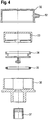
- Fig. 4 shows schematically and in an exploded view a pressure control device 13 of an embodiment in accordance with the invention.
- the pressure control device 13 is associated with the container and is in use mounted on the outlet 12 itself which is placed in the outlet opening of the container 1.
- the pressure control device is used for dispensing the fluid within a predetermined pressure range.
- the pressure control device 13 comprises the following parts: an upper cap 32 having a fluid exit, an inner cap 33, a piston 34, an O-ring 35, a main body 36 and a stopping member 37. The way these parts are assembled in use in the pressure control device 13 is shown in Fig. 1 .
- Fig. 5 shows an assembly comprising a container (of which only an upper part is shown) having a fluid chamber (not shown) for holding a fluid which is to be dispensed and an outlet 12 adapted for connection to the container 1 for releasing the fluid from the fluid chamber.
- the outlet 12 comprises a moveable blocking element, for example stem 25 having part 30, which can adopt a release position as is shown in Fig. 6 , in which the blocking element unblocks in the outlet 12 a fluid path for releasing fluid from the fluid chamber toward the pressure control device 13.
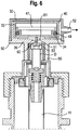
- Fig. 6 shows an assembly comprising a container (of which only an upper part is shown) having a fluid chamber (not shown) for holding a fluid which is to be dispensed and an outlet 12 adapted for connection to the container 1 for releasing the fluid from the fluid chamber.
- the outlet 12 comprises a moveable blocking element, for example stem 25 having part 30, which can adopt a release position as is shown in Fig. 6 , in which the blocking element unblocks in the outlet 12 a fluid path
- the blocking element can also adopt a blocking position for blocking at a fluid closing point C the fluid path in the outlet 12 so that fluid cannot be released from the fluid chamber of the container 1 into the outlet 12.
- the container 1 further has a high pressure chamber 4 for holding gas for driving the fluid towards the outlet 12.
- the outlet 12 further comprises a valve 40 for filling the high pressure chamber 4 with pressurized gas.
- Valve 40 is openable at a gas opening point 41 which is positioned in the outlet 12 with regard to the fluid path for releasing fluid, downstream of the fluid closing point C.
- the assembly further comprises a connector 42 for connecting the outlet 12 with a supply for highly pressurized gas.
- the assembly is further arranged so that when the connector 42 is connected to the outlet 12 and highly pressurized gas is supplied to the outlet 12, the blocking element, in this example part 30 of stem 25, is under the influence of the highly pressurized gas put in its blocking position. It is also possible that the blocking element is mechanically pushed into the blocking position, independent of the presence of a flow of high pressurized gas.
- the blocking element in the blocking position is shown in Fig. 5 .
- the arrow P indicates the supply of the pressurized gas.
- the impact of the gas is in use high enough to move stem 25 downward against the spring force provided by spring 26, so that the blocking element closes the fluid path for releasing fluid.
- the outlet 12 and the connector 42 are further arranged such that when the connector 42 is connected to the outlet 12, the valve 40 can be opened due to mechanical engagement of the connector 42 and the outlet 12.
- this facility is arranged as follows.
- the stem holder cup 22 is made of a rather stiff, preferably metal, material.
- an annular space 43 available for communication with the high pressure chamber 4.
- the outlet comprises an O-ring 23, which is as shown in Fig. 5 and in Fig. 1 sealingly placed inside the stem holder cup 22 between the stem holder cup and a top part of the stem holder 24.
- the connector 42 may, as shown, further be provided with jaws 45.
- the jaws 45 When the jaws 45 are pressed against an outer wall 55 of the stem holder cup 22, the stem holder cup 22 is at the pressed positions squeezed radially inwards, in this example at a relatively low position of the stem holder cup 22.
- an upper part of the stem holder cup 22 moves slightly radially outwards. This causes the sealing of the O-ring 23 to be discontinued.
- stem 25 moves into its blocking position so that gas will not enter the hollow guiding member 11.
- stem 25 may also be pushed mechanically, i.e. without the occurrence of a gas flow, into the blocking position. For instance, when the connector 42 "rests" on the stem 25 as shown in Fig. 5 , the part 30 of the stem is put in the blocking position. Once the fluid flow path is as such closed off at the fluid closing point C, the flow of high pressurized gas, as schematically indicated by arrow P, can commence.
- valve 40 in Fig. 6 which is different from the embodiment of valve 40 shown in Fig. 5 .
- valve 40 will open up and a fluid path will exist between an inner space of stem holder 24 and the annular space 43.
- Fig. 1 shows a starting point for the use of the Fig. 6 embodiment.
- stem 25 is under the influence of spring 26 pushed upward so that outlet channel 29 is blocked off by O-ring 23.
- O-ring 23 In other words, in this configuration there is no fluid connection between the fluid chamber 2 and a position D, downstream the outlet 12.
- stem 25 can be pushed downward by someone who operates the container for dispensing a fluid, is in this embodiment deliberately made limited, so that part 30 of stem 25 can under those circumstances not close entrance 31 of stem holder 24. It is under these circumstances that a fluid connection will be formed between a position in the hollow guiding member 11 and position D downstream of the outlet 12.
- a reference pressure chamber 47 is formed by an inner cap 33 and the earlier described piston 34. Although this predetermined pressure could be applied by a spring positioned in reference chamber 47, in the embodiment shown, the reference pressure is applied by a gas present in the reference chamber 47 at the reference pressure.
- the piston 34 is provided with a sealing ring 35 for preserving the gas in the reference pressure chamber 47.
- the cap 33 is mounted on a main body 36.
- Mounted over the inner cap 33 and on the main body 36 is an upper cap 32 which is provided with an exit 52 for the fluid to be dispensed.
- the main body 36 has a lower part 60 which is arranged to be mounted on an upper part of the stem 25.
- the lower part 60 of the main body 36 has a length suitable for ensuring that the stem 25 is pushed to a position in which the channel outlet 29 is unblocked and the entrance 31 of the outlet 12 is unblocked.
- the lower part 6 of the main body abuts stem holder cup 22, so that pushing the pressure control device 13 further down is not possible. In this way also the extent to which stem 25 can be pushed downwards is limited.
- the piston 34 of the pressure control device 13 is provided with a piston stem 62 which at its lower end is provided with a relatively small blocking element 53.
- the stem 25 extends through an opening 61, which can be blocked by blocking element 53, depending on the position of the piston 34.
- the pressure in the reference chamber 47 higher than the atmospheric pressure and lower than the pressure of the fluid to be dispensed at position D when the pressure control device is pressed down to allow a fluid connection between the hollow guide member 11 and position D to be formed.
- the pressure at position D could for instance be about 4 bar, depending on the pressure in the high pressure chamber 4 and the resistance formed by hollow guide member 11 and outlet 12.
- the opening 61 will initially be unblocked. Once fluid flows toward the pressure control device at position D, the pressure of the fluid downstream the opening 61 and/or blocking element 53 will contribute to the positioning of the piston 34. Fluid pressure experienced by the relatively small blocking element 53 does also contribute to the positioning of the piston 34, in proportion to the size of the blocking element 53. If the pressure of the fluid downstream the opening 61 and blocking element 53 is higher than the reference pressure in the reference chamber, the piston 34 will move upwards and the blocking element 53 will block opening 61. The pressure of the fluid downstream the opening 61 will then quickly drop due to dispensing via exit 52. Once the reference pressure becomes higher than the pressure downstream the opening 61, the piston will move downwards and opening 61 will reopen again, etc. This mechanism ensures that the fluid is dispensed with a pressure within a predetermined range.
- the fluid to be dispensed may first be put in the container. Then the guide member 11 and moveable element 5 can be placed into the container 1. The outlet 12 can be placed so that an outlet opening of the container is incorporated in the outlet 12. The high pressure chamber 2 can then be filled with gas in a way described above. Finally, the pressure control device is placed onto stem 25.
- the connector 42 can be a single part or multiple part connector.
- the movement of jaws 45 may be independent of the supply of highly pressurized gas, indicated by arrow P.
Landscapes
- Chemical & Material Sciences (AREA)
- Dispersion Chemistry (AREA)
- Engineering & Computer Science (AREA)
- Mechanical Engineering (AREA)
- Containers And Packaging Bodies Having A Special Means To Remove Contents (AREA)
Claims (16)
- Récipient (1) pour contenir un fluide comprenant : une chambre à fluide (2) ayant une paroi intérieure (3) ; une ouverture de sortie ; et une chambre haute pression (4) pour entraîner le fluide vers l'ouverture de sortie ; dans lequel le récipient comprend en outre en tant qu'au moins une partie d'un séparateur entre la chambre haute pression et la chambre à fluide un élément mobile (5) pour avancer dans un sens de mouvement prédéterminé à travers le récipient d'une première position à une seconde position pour réduire un volume de la chambre à fluide quand du fluide est distribué via l'ouverture de sortie, la première et la seconde position de l'élément mobile étant chacune une position où l'élément mobile a un contact avec la paroi intérieure, dans lequel une première (I-I) et une seconde (II-II) section transversale de la chambre à fluide prise transversalement à la direction de mouvement respectivement au niveau de la première et de la seconde position ont des dimensions différentes, dans lequel au niveau de chaque position suivante que l'élément mobile atteint tout en avançant dans le sens prédéterminé, la section transversale du récipient est plus grande que la section transversale au niveau d'une position précédente, dans lequel l'élément mobile comprend une paroi imperméable entre la chambre à fluide et la chambre haute pression, et dans lequel l'élément mobile est un élément élastique qui est sollicité vers une expansion dans des directions transversales par rapport au sens prédéterminé de sorte qu'un contact étroit entre l'élément et la paroi intérieure du récipient est maintenu pendant le mouvement de l'élément mobile de la première à la seconde position.
- Récipient (1) selon la revendication 1, dans lequel dans une position verticale du récipient, la première position est au-dessus de la seconde position.
- Récipient (1) selon l'une quelconque des revendications précédentes, dans lequel l'élément mobile est mobile dans sa totalité.
- Récipient (1) selon l'une quelconque des revendications précédentes, dans lequel l'élément mobile a un côté concave faisant face à la chambre haute pression.
- Récipient (1) selon l'une quelconque des revendications précédentes, dans lequel l'élément mobile a un côté convexe faisant face à la chambre à fluide.
- Récipient (1) selon l'une quelconque des revendications précédentes, dans lequel l'élément mobile comprend un caoutchouc ou un plastique élastique.
- Récipient (1) selon l'une quelconque des revendications précédentes, dans lequel l'élément mobile est sollicité par pliage de portions extérieures (9) de l'élément élastique vers la chambre haute pression.
- Récipient (1) selon l'une quelconque des revendications précédentes, dans lequel l'élément mobile est muni d'un anneau relativement raide (8) pour obtenir une partie relativement raide de l'élément élastique à l'intérieur de l'anneau et une partie relativement souple à l'extérieur de l'anneau.
- Récipient (1) selon l'une quelconque des revendications précédentes, dans lequel l'élément mobile possède au niveau d'une partie qui maintient un contact avec la paroi intérieure du récipient une souplesse qui est plus élevée que la souplesse au niveau d'une partie qui est exempte de contact avec la paroi intérieure du récipient.
- Récipient (1) selon l'une quelconque des revendications précédentes, dans lequel l'élément mobile et la paroi intérieure sont agencés de façon coaxiale.
- Récipient (1) selon l'une quelconque des revendications précédentes, dans lequel le récipient a une symétrie de rotation par rapport au sens prédéterminé.
- Récipient (1) selon l'une quelconque des revendications précédentes, dans lequel le récipient comprend un élément de guidage (11) pour guider le mouvement de l'élément mobile dans le sens prédéterminé.
- Récipient (1) selon la revendication 12, dans lequel l'élément mobile et l'élément de guidage (11) sont agencés de façon coaxiale à l'intérieur du récipient.
- Récipient (1) selon la revendication 12 ou 13, dans lequel l'élément de guidage est creux et agencé pour le transport du fluide depuis la chambre à fluide vers l'ouverture de sortie.
- Récipient (1) selon l'une quelconque des revendications précédentes, dans lequel le récipient est associé à un dispositif de commande de pression (13) pour distribuer le fluide à l'intérieur d'une plage de pressions prédéterminée, le récipient et le dispositif de commande de pression étant conçus pour maintenir lors de l'utilisation une connexion pour le flux du fluide allant du récipient au dispositif de commande de pression.
- Ensemble comprenant:un récipient (1) selon l'une quelconque des revendications précédentes ; etune sortie (12) conçue pour connexion au récipient pour libérer le fluide provenant de la chambre à fluide (2),dans lequel la sortie (12) comprend un élément de blocage mobile (25, 30) qui peut adopter une position de libération dans laquelle l'élément de blocage débloque dans la sortie un chemin de fluide pour libérer du fluide provenant de la chambre à fluide, et dans lequel l'élément de blocage peut adopter une position de blocage pour bloquer au niveau d'un point de fermeture pour fluide (C) le chemin de fluide dans la sortie (12) de sorte que du fluide ne peut pas être libéré en provenance de la chambre à fluide (2).
Priority Applications (1)
| Application Number | Priority Date | Filing Date | Title |
|---|---|---|---|
| PL08717698T PL2134623T3 (pl) | 2007-03-12 | 2008-03-12 | Pojemnik do przechowywania płynu i zespół pojemnika i wylotu |
Applications Claiming Priority (2)
| Application Number | Priority Date | Filing Date | Title |
|---|---|---|---|
| GBGB0704745.9A GB0704745D0 (en) | 2007-03-12 | 2007-03-12 | A container for holding a fluid and an assembly of a container and an outlet |
| PCT/EP2008/052952 WO2008110574A1 (fr) | 2007-03-12 | 2008-03-12 | Récipient destiné à contenir un liquide et ensemble de récipient et d'orifice de sortie |
Publications (2)
| Publication Number | Publication Date |
|---|---|
| EP2134623A1 EP2134623A1 (fr) | 2009-12-23 |
| EP2134623B1 true EP2134623B1 (fr) | 2019-03-06 |
Family
ID=37988825
Family Applications (1)
| Application Number | Title | Priority Date | Filing Date |
|---|---|---|---|
| EP08717698.8A Not-in-force EP2134623B1 (fr) | 2007-03-12 | 2008-03-12 | Récipient destiné à contenir un liquide et ensemble de récipient et d'orifice de sortie |
Country Status (7)
| Country | Link |
|---|---|
| US (1) | US8490819B2 (fr) |
| EP (1) | EP2134623B1 (fr) |
| JP (1) | JP5329443B2 (fr) |
| ES (1) | ES2718639T3 (fr) |
| GB (1) | GB0704745D0 (fr) |
| PL (1) | PL2134623T3 (fr) |
| WO (1) | WO2008110574A1 (fr) |
Families Citing this family (2)
| Publication number | Priority date | Publication date | Assignee | Title |
|---|---|---|---|---|
| US10159385B2 (en) * | 2016-11-15 | 2018-12-25 | Colgate-Palmolive Company | Dispenser |
| GB2597484A (en) * | 2020-07-22 | 2022-02-02 | Innovolo Ltd | Aerosol canister |
Family Cites Families (11)
| Publication number | Priority date | Publication date | Assignee | Title |
|---|---|---|---|---|
| US3099370A (en) * | 1958-12-24 | 1963-07-30 | American Can Co | Dispensing container for viscous products |
| NL130949C (fr) * | 1964-02-20 | |||
| DE2553571A1 (de) * | 1974-12-17 | 1976-06-24 | Rosalba Senegaglia | Herstellungsverfahren fuer zweikammerdruckdosen mit eingebautem verformbaren behaelter und bauteile zur durchfuehrung des verfahrens |
| US4106674A (en) * | 1975-09-24 | 1978-08-15 | Schultz Robert S | Pressure-operated container for viscous products |
| JPS591380A (ja) * | 1982-06-15 | 1984-01-06 | 綿木 善光 | スプレ−缶容器 |
| DE19632329A1 (de) * | 1996-08-10 | 1998-02-12 | Rathor Ag | Druckdosen-Mehrwegventil |
| EP0994042B1 (fr) * | 1998-03-03 | 2007-07-11 | Osaka Shipbuilding Co., Ltd. | Produit d'aerosol et procede de fabrication de celui-ci |
| FR2785268B1 (fr) * | 1998-10-28 | 2001-01-19 | Sofab | Valve pour reservoir a poche |
| CN100447060C (zh) | 2002-08-26 | 2008-12-31 | 株式会社托普 | 排出装置 |
| JP3823077B2 (ja) * | 2002-08-26 | 2006-09-20 | 株式会社トップ | 吐出装置 |
| JP2006124016A (ja) * | 2004-11-01 | 2006-05-18 | Katsutoshi Masuda | 流動体貯留容器 |
-
2007
- 2007-03-12 GB GBGB0704745.9A patent/GB0704745D0/en not_active Ceased
-
2008
- 2008-03-12 JP JP2009553133A patent/JP5329443B2/ja not_active Expired - Fee Related
- 2008-03-12 US US12/530,802 patent/US8490819B2/en not_active Expired - Fee Related
- 2008-03-12 PL PL08717698T patent/PL2134623T3/pl unknown
- 2008-03-12 ES ES08717698T patent/ES2718639T3/es active Active
- 2008-03-12 EP EP08717698.8A patent/EP2134623B1/fr not_active Not-in-force
- 2008-03-12 WO PCT/EP2008/052952 patent/WO2008110574A1/fr not_active Ceased
Non-Patent Citations (1)
| Title |
|---|
| None * |
Also Published As
| Publication number | Publication date |
|---|---|
| GB0704745D0 (en) | 2007-04-18 |
| JP5329443B2 (ja) | 2013-10-30 |
| JP2010520842A (ja) | 2010-06-17 |
| PL2134623T3 (pl) | 2019-08-30 |
| ES2718639T3 (es) | 2019-07-03 |
| US8490819B2 (en) | 2013-07-23 |
| US20100213196A1 (en) | 2010-08-26 |
| WO2008110574A1 (fr) | 2008-09-18 |
| EP2134623A1 (fr) | 2009-12-23 |
Similar Documents
| Publication | Publication Date | Title |
|---|---|---|
| CA2806384C (fr) | Soupape d'aerosol a debit eleve | |
| EP2655893B1 (fr) | Dispositifs de pompe | |
| EP1622818B1 (fr) | Aerosol avec valve de distribution pour produits multi-composants | |
| EP2780254B1 (fr) | Système de distribution à poche et à pompe | |
| US20140158719A1 (en) | Metering valve | |
| JP6318311B1 (ja) | 流動性物質吐出システムのための作動システム | |
| EP3414181B1 (fr) | Dispositif de distribution à action unique à manchon coulissant | |
| JP2019505377A (ja) | プラグを有する摺動スリーブを伴う単動式分注装置発明の背景 | |
| EP2134623B1 (fr) | Récipient destiné à contenir un liquide et ensemble de récipient et d'orifice de sortie | |
| CN110740819A (zh) | 用于可流动产品封装的泵式分配机构 | |
| ES2848202T3 (es) | Válvula de dispensación que incorpora una válvula de dosificación | |
| US8042715B2 (en) | Dispensing closure comprising a safety system | |
| US5083593A (en) | Flip-flop seal | |
| HK1125608B (en) | Dispensing closure comprising a safety system | |
| WO2013106830A1 (fr) | Régulateur de débit pour distribution de fluide sous pression à partir d'un système récipient fermé |
Legal Events
| Date | Code | Title | Description |
|---|---|---|---|
| PUAI | Public reference made under article 153(3) epc to a published international application that has entered the european phase |
Free format text: ORIGINAL CODE: 0009012 |
|
| 17P | Request for examination filed |
Effective date: 20091012 |
|
| AK | Designated contracting states |
Kind code of ref document: A1 Designated state(s): AT BE BG CH CY CZ DE DK EE ES FI FR GB GR HR HU IE IS IT LI LT LU LV MC MT NL NO PL PT RO SE SI SK TR |
|
| DAX | Request for extension of the european patent (deleted) | ||
| 17Q | First examination report despatched |
Effective date: 20120502 |
|
| RAP1 | Party data changed (applicant data changed or rights of an application transferred) |
Owner name: PACKAGING TECHNOLOGY PARTICIPATION NETHERLANDS B.V |
|
| GRAP | Despatch of communication of intention to grant a patent |
Free format text: ORIGINAL CODE: EPIDOSNIGR1 |
|
| STAA | Information on the status of an ep patent application or granted ep patent |
Free format text: STATUS: GRANT OF PATENT IS INTENDED |
|
| INTG | Intention to grant announced |
Effective date: 20181022 |
|
| GRAS | Grant fee paid |
Free format text: ORIGINAL CODE: EPIDOSNIGR3 |
|
| GRAA | (expected) grant |
Free format text: ORIGINAL CODE: 0009210 |
|
| STAA | Information on the status of an ep patent application or granted ep patent |
Free format text: STATUS: THE PATENT HAS BEEN GRANTED |
|
| AK | Designated contracting states |
Kind code of ref document: B1 Designated state(s): AT BE BG CH CY CZ DE DK EE ES FI FR GB GR HR HU IE IS IT LI LT LU LV MC MT NL NO PL PT RO SE SI SK TR |
|
| REG | Reference to a national code |
Ref country code: GB Ref legal event code: FG4D |
|
| REG | Reference to a national code |
Ref country code: CH Ref legal event code: EP Ref country code: AT Ref legal event code: REF Ref document number: 1104225 Country of ref document: AT Kind code of ref document: T Effective date: 20190315 |
|
| REG | Reference to a national code |
Ref country code: DE Ref legal event code: R096 Ref document number: 602008059228 Country of ref document: DE |
|
| REG | Reference to a national code |
Ref country code: IE Ref legal event code: FG4D |
|
| REG | Reference to a national code |
Ref country code: NL Ref legal event code: FP |
|
| REG | Reference to a national code |
Ref country code: ES Ref legal event code: FG2A Ref document number: 2718639 Country of ref document: ES Kind code of ref document: T3 Effective date: 20190703 |
|
| REG | Reference to a national code |
Ref country code: LT Ref legal event code: MG4D |
|
| PG25 | Lapsed in a contracting state [announced via postgrant information from national office to epo] |
Ref country code: SE Free format text: LAPSE BECAUSE OF FAILURE TO SUBMIT A TRANSLATION OF THE DESCRIPTION OR TO PAY THE FEE WITHIN THE PRESCRIBED TIME-LIMIT Effective date: 20190306 Ref country code: FI Free format text: LAPSE BECAUSE OF FAILURE TO SUBMIT A TRANSLATION OF THE DESCRIPTION OR TO PAY THE FEE WITHIN THE PRESCRIBED TIME-LIMIT Effective date: 20190306 Ref country code: NO Free format text: LAPSE BECAUSE OF FAILURE TO SUBMIT A TRANSLATION OF THE DESCRIPTION OR TO PAY THE FEE WITHIN THE PRESCRIBED TIME-LIMIT Effective date: 20190606 Ref country code: LT Free format text: LAPSE BECAUSE OF FAILURE TO SUBMIT A TRANSLATION OF THE DESCRIPTION OR TO PAY THE FEE WITHIN THE PRESCRIBED TIME-LIMIT Effective date: 20190306 |
|
| PG25 | Lapsed in a contracting state [announced via postgrant information from national office to epo] |
Ref country code: GR Free format text: LAPSE BECAUSE OF FAILURE TO SUBMIT A TRANSLATION OF THE DESCRIPTION OR TO PAY THE FEE WITHIN THE PRESCRIBED TIME-LIMIT Effective date: 20190607 Ref country code: LV Free format text: LAPSE BECAUSE OF FAILURE TO SUBMIT A TRANSLATION OF THE DESCRIPTION OR TO PAY THE FEE WITHIN THE PRESCRIBED TIME-LIMIT Effective date: 20190306 Ref country code: HR Free format text: LAPSE BECAUSE OF FAILURE TO SUBMIT A TRANSLATION OF THE DESCRIPTION OR TO PAY THE FEE WITHIN THE PRESCRIBED TIME-LIMIT Effective date: 20190306 Ref country code: BG Free format text: LAPSE BECAUSE OF FAILURE TO SUBMIT A TRANSLATION OF THE DESCRIPTION OR TO PAY THE FEE WITHIN THE PRESCRIBED TIME-LIMIT Effective date: 20190606 |
|
| REG | Reference to a national code |
Ref country code: AT Ref legal event code: MK05 Ref document number: 1104225 Country of ref document: AT Kind code of ref document: T Effective date: 20190306 |
|
| PG25 | Lapsed in a contracting state [announced via postgrant information from national office to epo] |
Ref country code: CZ Free format text: LAPSE BECAUSE OF FAILURE TO SUBMIT A TRANSLATION OF THE DESCRIPTION OR TO PAY THE FEE WITHIN THE PRESCRIBED TIME-LIMIT Effective date: 20190306 Ref country code: RO Free format text: LAPSE BECAUSE OF FAILURE TO SUBMIT A TRANSLATION OF THE DESCRIPTION OR TO PAY THE FEE WITHIN THE PRESCRIBED TIME-LIMIT Effective date: 20190306 Ref country code: EE Free format text: LAPSE BECAUSE OF FAILURE TO SUBMIT A TRANSLATION OF THE DESCRIPTION OR TO PAY THE FEE WITHIN THE PRESCRIBED TIME-LIMIT Effective date: 20190306 Ref country code: PT Free format text: LAPSE BECAUSE OF FAILURE TO SUBMIT A TRANSLATION OF THE DESCRIPTION OR TO PAY THE FEE WITHIN THE PRESCRIBED TIME-LIMIT Effective date: 20190706 Ref country code: SK Free format text: LAPSE BECAUSE OF FAILURE TO SUBMIT A TRANSLATION OF THE DESCRIPTION OR TO PAY THE FEE WITHIN THE PRESCRIBED TIME-LIMIT Effective date: 20190306 |
|
| REG | Reference to a national code |
Ref country code: CH Ref legal event code: PL |
|
| REG | Reference to a national code |
Ref country code: DE Ref legal event code: R097 Ref document number: 602008059228 Country of ref document: DE |
|
| PG25 | Lapsed in a contracting state [announced via postgrant information from national office to epo] |
Ref country code: AT Free format text: LAPSE BECAUSE OF FAILURE TO SUBMIT A TRANSLATION OF THE DESCRIPTION OR TO PAY THE FEE WITHIN THE PRESCRIBED TIME-LIMIT Effective date: 20190306 Ref country code: IS Free format text: LAPSE BECAUSE OF FAILURE TO SUBMIT A TRANSLATION OF THE DESCRIPTION OR TO PAY THE FEE WITHIN THE PRESCRIBED TIME-LIMIT Effective date: 20190706 |
|
| PLBE | No opposition filed within time limit |
Free format text: ORIGINAL CODE: 0009261 |
|
| STAA | Information on the status of an ep patent application or granted ep patent |
Free format text: STATUS: NO OPPOSITION FILED WITHIN TIME LIMIT |
|
| REG | Reference to a national code |
Ref country code: CH Ref legal event code: AECN Free format text: DAS PATENT WURDE AUFGRUND DES WEITERBEHANDLUNGSANTRAGS VOM 8.1.2020 REAKTIVIERT. |
|
| PG25 | Lapsed in a contracting state [announced via postgrant information from national office to epo] |
Ref country code: LI Free format text: LAPSE BECAUSE OF NON-PAYMENT OF DUE FEES Effective date: 20190331 Ref country code: IE Free format text: LAPSE BECAUSE OF NON-PAYMENT OF DUE FEES Effective date: 20190312 Ref country code: MC Free format text: LAPSE BECAUSE OF FAILURE TO SUBMIT A TRANSLATION OF THE DESCRIPTION OR TO PAY THE FEE WITHIN THE PRESCRIBED TIME-LIMIT Effective date: 20190306 Ref country code: CH Free format text: LAPSE BECAUSE OF NON-PAYMENT OF DUE FEES Effective date: 20190331 Ref country code: DK Free format text: LAPSE BECAUSE OF FAILURE TO SUBMIT A TRANSLATION OF THE DESCRIPTION OR TO PAY THE FEE WITHIN THE PRESCRIBED TIME-LIMIT Effective date: 20190306 |
|
| 26N | No opposition filed |
Effective date: 20191209 |
|
| PG25 | Lapsed in a contracting state [announced via postgrant information from national office to epo] |
Ref country code: SI Free format text: LAPSE BECAUSE OF FAILURE TO SUBMIT A TRANSLATION OF THE DESCRIPTION OR TO PAY THE FEE WITHIN THE PRESCRIBED TIME-LIMIT Effective date: 20190306 |
|
| PG25 | Lapsed in a contracting state [announced via postgrant information from national office to epo] |
Ref country code: TR Free format text: LAPSE BECAUSE OF FAILURE TO SUBMIT A TRANSLATION OF THE DESCRIPTION OR TO PAY THE FEE WITHIN THE PRESCRIBED TIME-LIMIT Effective date: 20190306 |
|
| PGFP | Annual fee paid to national office [announced via postgrant information from national office to epo] |
Ref country code: DE Payment date: 20200309 Year of fee payment: 13 Ref country code: IT Payment date: 20200306 Year of fee payment: 13 Ref country code: GB Payment date: 20200309 Year of fee payment: 13 Ref country code: PL Payment date: 20200227 Year of fee payment: 13 Ref country code: NL Payment date: 20200306 Year of fee payment: 13 |
|
| PG25 | Lapsed in a contracting state [announced via postgrant information from national office to epo] |
Ref country code: LI Free format text: LAPSE BECAUSE OF NON-PAYMENT OF DUE FEES Effective date: 20190331 Ref country code: CH Free format text: LAPSE BECAUSE OF NON-PAYMENT OF DUE FEES Effective date: 20190331 |
|
| PGFP | Annual fee paid to national office [announced via postgrant information from national office to epo] |
Ref country code: CH Payment date: 20200108 Year of fee payment: 12 Ref country code: LU Payment date: 20200311 Year of fee payment: 13 Ref country code: BE Payment date: 20200306 Year of fee payment: 13 |
|
| PGRI | Patent reinstated in contracting state [announced from national office to epo] |
Ref country code: LI Effective date: 20200114 Ref country code: CH Effective date: 20200114 |
|
| PG25 | Lapsed in a contracting state [announced via postgrant information from national office to epo] |
Ref country code: MT Free format text: LAPSE BECAUSE OF NON-PAYMENT OF DUE FEES Effective date: 20190312 |
|
| PGFP | Annual fee paid to national office [announced via postgrant information from national office to epo] |
Ref country code: FR Payment date: 20200306 Year of fee payment: 13 |
|
| PGFP | Annual fee paid to national office [announced via postgrant information from national office to epo] |
Ref country code: ES Payment date: 20200401 Year of fee payment: 13 |
|
| REG | Reference to a national code |
Ref country code: CH Ref legal event code: PL |
|
| PG25 | Lapsed in a contracting state [announced via postgrant information from national office to epo] |
Ref country code: LI Free format text: LAPSE BECAUSE OF NON-PAYMENT OF DUE FEES Effective date: 20200331 Ref country code: CH Free format text: LAPSE BECAUSE OF NON-PAYMENT OF DUE FEES Effective date: 20200331 |
|
| PG25 | Lapsed in a contracting state [announced via postgrant information from national office to epo] |
Ref country code: CY Free format text: LAPSE BECAUSE OF FAILURE TO SUBMIT A TRANSLATION OF THE DESCRIPTION OR TO PAY THE FEE WITHIN THE PRESCRIBED TIME-LIMIT Effective date: 20190306 |
|
| PG25 | Lapsed in a contracting state [announced via postgrant information from national office to epo] |
Ref country code: HU Free format text: LAPSE BECAUSE OF FAILURE TO SUBMIT A TRANSLATION OF THE DESCRIPTION OR TO PAY THE FEE WITHIN THE PRESCRIBED TIME-LIMIT; INVALID AB INITIO Effective date: 20080312 |
|
| REG | Reference to a national code |
Ref country code: DE Ref legal event code: R119 Ref document number: 602008059228 Country of ref document: DE |
|
| REG | Reference to a national code |
Ref country code: NL Ref legal event code: MM Effective date: 20210401 |
|
| GBPC | Gb: european patent ceased through non-payment of renewal fee |
Effective date: 20210312 |
|
| REG | Reference to a national code |
Ref country code: BE Ref legal event code: MM Effective date: 20210331 |
|
| PG25 | Lapsed in a contracting state [announced via postgrant information from national office to epo] |
Ref country code: NL Free format text: LAPSE BECAUSE OF NON-PAYMENT OF DUE FEES Effective date: 20210401 Ref country code: LU Free format text: LAPSE BECAUSE OF NON-PAYMENT OF DUE FEES Effective date: 20210312 Ref country code: DE Free format text: LAPSE BECAUSE OF NON-PAYMENT OF DUE FEES Effective date: 20211001 Ref country code: FR Free format text: LAPSE BECAUSE OF NON-PAYMENT OF DUE FEES Effective date: 20210331 Ref country code: GB Free format text: LAPSE BECAUSE OF NON-PAYMENT OF DUE FEES Effective date: 20210312 |
|
| PG25 | Lapsed in a contracting state [announced via postgrant information from national office to epo] |
Ref country code: IT Free format text: LAPSE BECAUSE OF NON-PAYMENT OF DUE FEES Effective date: 20210312 |
|
| REG | Reference to a national code |
Ref country code: ES Ref legal event code: FD2A Effective date: 20220523 |
|
| PG25 | Lapsed in a contracting state [announced via postgrant information from national office to epo] |
Ref country code: ES Free format text: LAPSE BECAUSE OF NON-PAYMENT OF DUE FEES Effective date: 20210313 Ref country code: BE Free format text: LAPSE BECAUSE OF NON-PAYMENT OF DUE FEES Effective date: 20210331 |
|
| PG25 | Lapsed in a contracting state [announced via postgrant information from national office to epo] |
Ref country code: PL Free format text: LAPSE BECAUSE OF NON-PAYMENT OF DUE FEES Effective date: 20210312 |