EP2134987B1 - Antriebsvorrichtung für doppelwellenmischer - Google Patents
Antriebsvorrichtung für doppelwellenmischer Download PDFInfo
- Publication number
- EP2134987B1 EP2134987B1 EP07724248A EP07724248A EP2134987B1 EP 2134987 B1 EP2134987 B1 EP 2134987B1 EP 07724248 A EP07724248 A EP 07724248A EP 07724248 A EP07724248 A EP 07724248A EP 2134987 B1 EP2134987 B1 EP 2134987B1
- Authority
- EP
- European Patent Office
- Prior art keywords
- shaft
- mixer
- transmission
- drive
- synchronization
- Prior art date
- Legal status (The legal status is an assumption and is not a legal conclusion. Google has not performed a legal analysis and makes no representation as to the accuracy of the status listed.)
- Not-in-force
Links
Images

Classifications
-
- F—MECHANICAL ENGINEERING; LIGHTING; HEATING; WEAPONS; BLASTING
- F16—ENGINEERING ELEMENTS AND UNITS; GENERAL MEASURES FOR PRODUCING AND MAINTAINING EFFECTIVE FUNCTIONING OF MACHINES OR INSTALLATIONS; THERMAL INSULATION IN GENERAL
- F16H—GEARING
- F16H37/00—Combinations of mechanical gearings, not provided for in groups F16H1/00 - F16H35/00
- F16H37/02—Combinations of mechanical gearings, not provided for in groups F16H1/00 - F16H35/00 comprising essentially only toothed or friction gearings
- F16H37/06—Combinations of mechanical gearings, not provided for in groups F16H1/00 - F16H35/00 comprising essentially only toothed or friction gearings with a plurality of driving or driven shafts; with arrangements for dividing torque between two or more intermediate shafts
- F16H37/065—Combinations of mechanical gearings, not provided for in groups F16H1/00 - F16H35/00 comprising essentially only toothed or friction gearings with a plurality of driving or driven shafts; with arrangements for dividing torque between two or more intermediate shafts with a plurality of driving or driven shafts
-
- B—PERFORMING OPERATIONS; TRANSPORTING
- B01—PHYSICAL OR CHEMICAL PROCESSES OR APPARATUS IN GENERAL
- B01F—MIXING, e.g. DISSOLVING, EMULSIFYING OR DISPERSING
- B01F27/00—Mixers with rotary stirring devices in fixed receptacles; Kneaders
- B01F27/60—Mixers with rotary stirring devices in fixed receptacles; Kneaders with stirrers rotating about a horizontal or inclined axis
- B01F27/70—Mixers with rotary stirring devices in fixed receptacles; Kneaders with stirrers rotating about a horizontal or inclined axis with paddles, blades or arms
- B01F27/701—Mixers with rotary stirring devices in fixed receptacles; Kneaders with stirrers rotating about a horizontal or inclined axis with paddles, blades or arms comprising two or more shafts, e.g. in consecutive mixing chambers
- B01F27/702—Mixers with rotary stirring devices in fixed receptacles; Kneaders with stirrers rotating about a horizontal or inclined axis with paddles, blades or arms comprising two or more shafts, e.g. in consecutive mixing chambers with intermeshing paddles
Definitions
- the present invention relates to a double shaft mixer drive apparatus having a drive motor and a transmission in which a transmission input shaft is connected to an engine output shaft of the drive motor, a transmission output shaft drives a mixer shaft of the twin shaft mixer and a synchronization shaft is provided, and a double shaft mixer.
- Dual shaft mixers comprise a mixing vessel in which two mixer shafts are aligned parallel to each other and have radially arranged mixing vanes.
- Double-shaft mixers can be used for mixing different mixes, in particular for mixing building material mixtures such as concrete or mortar mixes.
- the mix is mixed in the mixing container by moving the mixing blades of the two rotating mixer shafts through the mix.
- the two mixer shafts are aligned parallel to one another at a distance such that the mixing blades could theoretically touch each other. However, since this would lead to damage and destruction of the mixing blades, it is necessary to match the rotations of the two mixer shafts so that the mixing blades do not touch in any case, to avoid damage to the mixing blades.
- Two gears are attached to the mixing vessel so that the transmission output shafts are engaged with the mixer shaft, respectively.
- two motors are provided, each driving one of the gears. Since the mixer waves, as already described, must run synchronously to each other, a synchronization of the motors must be achieved.
- a synchronization shaft is usually provided on both transmissions.
- the synchronization shafts are rigidly connected with each other so that the speeds of both transmissions are synchronized.
- the drive of each transmission through the engine is often via V-belts.
- toothed belts are used in constructions in which the synchronization takes place in front of the transmission, such as in a synchronization of the motor shafts.
- V-belt and timing belt age over time and either tear or the teeth of the belt can not ensure the synchronization of the waves safe.
- impact loads on the mixer shaft which can occur when mixing coarse mix, a high jerky force is acted on the belt, which can cause the toothed belt skips a tooth, and thus the synchronization is disturbed.
- the synchronization can also be done via a worm shaft.
- the belt tension must be adjusted, an exact alignment of the transmission elements is necessary and that the belt tension an additional load on the transmission is effected.
- twin-shaft mixer is out of the WO 0185322 A1 known.
- a two-shaft mixer with two gear designed as a planetary gear, which discloses a drive device according to the preamble of claim 1 is known from WO 02078829 A1 known.
- Object of the present invention is to provide a drive device for twin-shaft mixer, which synchronizes the mixer shafts safe, takes up little space and is inexpensive to manufacture.
- no drives are used via toothed belts, V-belts or chains or comparable transmissions.
- the latter transmission means have in common that the torque of the rotation is transmitted via tensile forces acting within the belt or the chain. Since the changing tensile forces cause wear in the course of the operating time, which can eventually cause a rupture of the drive belt, it is advantageous to eliminate such drive means within the drive train. In addition, there is the problem of slippage.
- the torque is transmitted from each of the motors to the corresponding transmission output shaft via a gear transmission.
- the gear transmission may include gearbox, bevel, planetary or worm gear ratios or the like.
- gearbox the different components of the torque transmission by means of compressive forces to each other. This means that the teeth of different gears are each loaded with compressive forces, which are caused by the teeth of adjacent gears.
- belt drives are used, which transmit the torque via tensile forces.
- the transmission is designed such that the axis of the motor, which corresponds in the orientation of the transmission input shaft, the synchronization shaft and the transmission wear shaft are not aligned parallel to each other.
- the known transmissions of the twin-shaft mixers usually have besides a transmission output shaft, which corresponds in the orientation of the mixer shaft, also a synchronization shaft, which is perpendicular to the mixer shaft in a plane parallel to the two mixer shafts, and also a motor output shaft, which is parallel to the synchronization shaft , From this Design results in that the engine must be arranged side of the transmission, which takes up a lot of space.
- the alignment of the axes described above is advantageously realized by a bevel gear.
- This bevel gear is driven by a drive bevel gear, which is advantageously connected directly to the transmission input shaft.
- Another bevel gear of the bevel gear which will be referred to as output bevel gear in the following, is connected to the mixer shaft, advantageously a transmission arrangement is interposed.
- the translation arrangement has the task to reduce the speed, so as to increase the torque.
- a Synchronkekegelrad is provided, which is connected torque-lockingly connected to the synchronization shaft.
- the synchronization of both gears are preferably rotationally rigidly connected to each other via a universal joint and / or coupling.
- the two motors are in direct engagement with the synchronization shafts via the gears. As a result, a synchronization of the motors is achieved.
- the toothed belt or V-belt drives used in the known double-shaft mixers require that the axis driving this drive must be aligned in parallel with the aborting axis.
- a bevel gear it is achieved that the gear input shaft, the transmission output shaft and the synchronization shaft can be in three different directions.
- the drive torque of the drive motor is completely directed to the corresponding mixer shaft and the synchronization shafts do not transmit a synchronization torque.
- the torque has a braking effect on the transmission and thus on the synchronization shaft.
- drive torque from the second drive motor is forwarded to the first transmission via the second transmission, which causes the second drive motor to indirectly indirectly drive the first mixer shaft, thus keeping both engines, transmissions, and mixer shafts at the same speed. The same applies if one of the drive motors fails or causes a lower drive speed or torque due to interference.
- the double-shaft mixer 2 comprises accordingly Fig. 1 a mixing container 20, in which two mixer shafts 5 are arranged. These mixer shafts comprise a plurality of blades 4 which face radially outwardly from the mixer shaft and have a scoop-shaped extension at the end. These mixing blades are arranged in a different angular position to the preceding, which is comparable to approximately steps of a spiral staircase.
- the mixer shafts 5 are connected at one axial end with a respective transmission 1 and 1 '.
- a drive motor 3 is provided at each of the gears. From the drive motor 3, the torque of the engine is transmitted via a transmission input shaft to the transmission 1 and 1 'via an engine output shaft, in which it is forwarded to a bevel gear.
- the bevel gear includes a driven bevel gear 22 to which torque of the motor is transmitted.
- This output bevel gear is via gear ratios with the transmission output shaft 7 ( Fig. 3 ), which leads from the transmission and is connected torsionally rigid with one of the mixer shafts 5.
- each of the drive motors 3 drives the corresponding mixer shaft 5.
- the two gears are engaged by means of a synchronization with each other.
- This synchronization is as in Fig. 2 shown schematically, realized by means of a synchronization drive 19, which comprises two universal joints.
- the synchronization drive ensures a rotationally rigid connection between the synchronization shafts 9 and thus for correspondingly synchronized rotational speeds of the transmission and thus of the mixer shafts.
- Fig. 3 shows the double-shaft mixer 2 in a side view, wherein it can be clearly seen that the transmission is fitted over a hollow shaft connection 7 on the mixer shaft and fixed on this.
- the transmission 1 is supported via a torque arm 13 with respect to the mixer.
- the drive motor 3 is arranged above the transmission 1 so that the motor rotation axis has a vertical orientation to the axis of the respective mixer shaft.
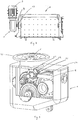
- Fig. 4 shows one of the two gears, which the left of the in Fig. 1 or 2 represented gear corresponds. Both gears are preferably mirror-symmetrical.
- the engine mounting flange 12 is provided, to which the engine 3 (not shown) is attached.
- the drive torque is transmitted from an engine output shaft directly to the transmission input shaft 6.
- This gear drive shaft 6 comprises at its lower end a drive bevel gear 21. This is connected to the driven bevel gear 22 in engagement.
- This output bevel gear 22 is about two subsequent, spur gears comprehensive Translation stages with a driven gear 24 which receives the transmission output shaft, not shown, connected.
- the gear ratios have the task to reduce the rotational speed of the engine and thus to increase the torque on the transmission output shaft.
- the driven bevel gear 22 is engaged with a synchronizing bevel gear 23 which is fixed to the synchronization shaft 9.
- an angle of 90 ° is present between the transmission drive shaft 6 with the drive bevel gear 21, the synchronization shaft 9 with the synchronization bevel gear 23 and the shaft of the driven bevel gear 22.
- the shaft of the driven bevel gear 22 and the output shaft have the same orientation. Since the axes of the driven bevel gear 22 and the synchronizing bevel gear 23 span here a horizontal plane, thus, the gear drive shaft 6, due to a 90 ° deflection in the vertical. Due to this design, it is realized that the drive motor 3 is located above the transmission. Out Fig. 3 it can be seen that the drive motor 3 in the longitudinal direction of the mixer is only slightly more expansive than the transmission. Out Fig. 2 It can be seen that the engine in the transverse direction is less bulky than the transmission, which also saves space.
- each synchronization shaft 9 comprises a fan wheel 10, which supplies the transmission 1 and the drive motor 3 cooling air.
Landscapes
- Engineering & Computer Science (AREA)
- General Engineering & Computer Science (AREA)
- Chemical & Material Sciences (AREA)
- Chemical Kinetics & Catalysis (AREA)
- Mechanical Engineering (AREA)
- Accessories For Mixers (AREA)
- Processing And Handling Of Plastics And Other Materials For Molding In General (AREA)
- Mixers Of The Rotary Stirring Type (AREA)
- Preparation Of Clay, And Manufacture Of Mixtures Containing Clay Or Cement (AREA)
Description
- Die vorliegenden Erfindung betrifft eine Antriebsvorrichtung für Doppelwellenmischer mit einem Antriebsmotor und einem Getriebe, bei welchem eine Getriebeantriebswelle an einer Motorabtriebswelle des Antriebsmotors verbunden ist, eine Getriebeabtriebswelle eine Mischerwelle des Doppelwellenmischers antreibt und eine Synchronisationswelle vorgesehen sind, sowie einen Doppelwellenmischer.
- Doppelwellenmischer umfassen einen Mischbehälter, in welchem zwei Mischerwellen parallel zueinander ausgerichtet sind und radial angeordnete Mischschaufeln aufweisen. Doppelwellenmischer können für das Mischen unterschiedlicher Mischgüter, insbesondere für das Mischen von Baustoffmischungen wie bspw. Beton oder Mörtelmischungen, verwendet werden. Das Mischgut wird in dem Mischbehälter dadurch durchmischt, dass die Mischschaufeln der beiden rotierenden Mischerwellen durch das Mischgut bewegt werden. Die beiden Mischerwellen sind einem Abstand zueinander parallel derart ausgerichtet, dass die Mischschaufeln sich theoretisch berühren könnten. Da dies jedoch zu Beschädigungen und Zerstörungen an den Mischschaufeln führen würde, ist es notwendig die Rotationen der beiden Mischerwellen derart abzugleichen, dass die Mischschaufeln sich in jedem Fall nicht berühren, um Beschädigungen der Mischschaufeln zu vermeiden. An dem Mischbehälter werden zwei Getriebe so befestigt, dass die Getriebeabtriebswellen jeweils mit der Mischerwelle in Eingriff stehen. Üblicherweise werden zwei Motoren vorgesehen, welche jeweils eines der Getriebe antreiben. Da die Mischerwellen, wie bereits beschrieben, zueinander synchron laufen müssen, muss eine Synchronisation der Motoren erreicht werden. Hierzu wird üblicherweise an beiden Getrieben je eine Synchronisationswelle vorgesehen. Die Synchronisationswellen sind miteinander drehsteif so verbunden, dass die Geschwindigkeiten beider Getriebe synchronisiert werden. Der Antrieb jedes Getriebes durch den Motor erfolgt häufig über Keilriemen. Alternativ werden auch Zahnriemen bei Konstruktionen eingesetzt, bei denen die Synchronisation vor dem Getriebe, wie etwa bei einer Synchronisation der Motorwellen, geschieht. Hierbei hat es sich als nachteilig erwiesen, dass die Keilriemen und Zahnriemen mit der Zeit altern und entweder reißen oder die Zähne des Zahnriemens die Synchronisation der Wellen nicht sicher gewährleisten können. Insbesondere bei stoßartigen Belastungen auf die Mischerwelle, welche bei dem Durchmischen groben Mischguts entstehen können, wird auf den Riemen eine hohe ruckartige Kraft ausgewirkt, welche bewirken kann, dass beim Zahnriemen ein Zahn überspringt, und somit die Synchronisation gestört ist. Ferner kann die Synchronisation auch über eine Schneckenwelle geschehen. Hier ist auch nachteilig, dass die Riemenspannung eingestellt werden muss, eine exakte Ausrichtung der Getriebeelemente notwendig ist und dass durch die Riemenspannung eine zusätzliche Belastung das Getriebe bewirkt wird.
- Als ein weiterer Nachteil des Standes der Technik hat es sich gezeigt, dass die Motoren und Getriebe an einer Stirnseite des Doppelwellenmischers nebeneinander bzw. hintereinander angeordnet sind und somit relativ viel Platz beanspruchen.
- Ferner sind Bauformen bekannt, welche zwei als Planetengetriebe ausführte Getriebe mit je einer Antriebs-, Abtriebs- und Synchronisationswelle aufweisen, wobei die Antriebswelle über einen Keilriementrieb durch den Motor angetrieben wird. Diese Bauformen weisen bauartbedingt den Nachteil eines größeren Platzbedarfs auf.
- Ein weiterer Zweiwellen-Mischer ist aus der
WO 0185322 A1 WO 02078829 A1 - Aufgabe der vorliegenden Erfindung ist es, eine Antriebsvorrichtung für Doppelwellenmischer zu schaffen, welche die Mischerwellen sicher synchronisiert, wenig Platz beansprucht und kostengünstig zu Fertigen ist.
- Diese Aufgabe wird erfindungsgemäß für eine Antriebsvorrichtung durch die im Anspruch 1 enthaltenen Merkmale und für einen Doppelwellenmischer durch die Merkmale des kennzeichnenden Teils des Anspruchs 5 gelöst. Zweckmäßige Weiterbildungen sind durch die in den Unteransprüchen enthaltenen Merkmale gekennzeichnet.
- Erfindungsgemäß wird die Drehmomentübertragung von der Motorabtriebswelle zu der Getriebeabtriebswelle, welche unmittelbar mit der Mischerwelle verbunden ist, ausschließlich über mittels mit Verzahnungen in Eingriff stehenden Wellen bewirkt. Erfindungsgemäß werden so keine Antriebe über Zahnriemen, Keilriemen oder Ketten oder vergleichbare Transmissionen verwendet. Den letztgenannten Übertragungsmitteln ist es gemein, dass das Drehmoment der Rotation über Zugkräfte übertragen wird, welche innerhalb des Riemens oder der Kette wirken. Da die wechselnden Zugkräfte im Laufe der Betriebszeit einen Verschleiß bewirken, was schließlich auch ein Reißen des Antriebsriemens verursachen kann, ist es vorteilhaft derartige Antriebsmittel innerhalb des Antriebsstrangs zu beseitigen. Außerdem besteht das Problem des Schlupfes. Erfindungsgemäß wird das Drehmoment von jedem der Motoren zu der entsprechenden Getriebeabtriebswelle über ein Zahnradgetriebe übertragen. Das Zahnradgetriebe kann Übersetzungen mittels Stirnrädern, Kegelrädern, Planetengetrieben oder Schneckenradtrieben oder ähnlichen umfassen. Bei einem Zahnradgetriebe wirken die unterschiedlichen Komponenten der Drehmomentübertragung mittels Druckkräften zueinander. Dies bedeutet, dass die Zähne unterschiedlicher Zahnräder jeweils mit Druckkräften belastet sind, welche von den Zähnen benachbarter Zahnräder bewirkt sind. Hierin ist ein Unterschied zu den aus dem Stand der Technik bekannten Getrieben zusehen, bei welchen Riementriebe verwendet werden, welche das Drehmoment über Zugkräfte übertragen.
- Durch die Verbindung von den Synchronisationswellen der beiden Getriebe, wird erreicht, dass beide Getriebe und somit beide Mischerwellen synchronisiert sind. Vorteilhafterweise ist das Getriebe derart ausgestaltet, dass die Achse des Motors, welche in der Ausrichtung der Getriebeantriebswelle entspricht, die Synchronisationswelle und die Getriebeabriebswelle jeweils zueinander nicht parallel ausgerichtet sind. Die bekannten Getriebe der Doppelwellenmischer weisen üblicherweise neben einer Getriebeabtriebwelle, die in der Ausrichtung der Mischerwelle entspricht, ferner eine Synchronisationswelle auf, welche in einer zu den beiden Mischerwellen parallelen Ebene senkrecht zu der Mischerwelle liegt, und ferner eine Motorabtriebswelle, welche parallel zu der Synchronisationswelle liegt. Aus dieser Bauform ergibt sich, dass der Motor seitlich des Getriebes angeordnet werden muss, was viel Platz beansprucht. Dieser Nachteil wird in vorteilhafter Weise dadurch beseitigt, dass die genannten Achsen nicht zueinander parallel ausgerichtet sind. So kann die Lage der Motorabtriebswelle in der Vertikalen, also senkrecht zur Ebene, in welcher die Mischerwellen liegen, angeordnet sein. Dadurch kann der Raum oberhalb des Getriebes optimal zur Anbringung des Motors verwendet werden. Alternativ kann der Antriebsmotor auch unterhalb des Getriebes liegen.
- Auch ist eine Ausrichtung der einzelnen Achsen in beliebige andere Richtungen denkbar.
- Die oben beschriebene Ausrichtung der Achsen wird vorteilhafter Weise durch ein Kegelradgetriebe realisiert. Dieses Kegelradgetriebe wird durch ein Antriebskegelrad angetrieben, welches in vorteilhafter Weise direkt mit der Getriebeantriebswelle verbunden ist. Ein weiteres Kegelrad des Kegelradgetriebes, welches im Folgenden Abtriebskegelrad genannt wird, ist mit der Mischerwelle verbunden, wobei vorteilhafter Weise eine Übersetzungsanordnung zwischengeschaltet ist. Die Übersetzungsanordnung hat die Aufgabe die Drehzahl zu reduzieren, um so das Drehmoment zu erhöhen. Als ein drittes Kegelrad des Kegelradgetriebes wird ein Synchronisationskegelrad vorgesehen, welches mit der Synchronisationswelle drehmomentschlüssig verbunden ist. Die Synchronisationswellen beider Getriebe sind vorzugsweise über ein Kardangelenk und/oder Kupplung rotationssteif miteinander verbunden. Bei der vorliegenden Erfindung stehen somit die beiden Motoren über die Getriebe mit den Synchronisationswellen in direktem Eingriff. Hierdurch wird eine Synchronisation der Motoren erreicht.
- Die bei den bekannten Doppelwellenmischern verwendeten Zahnriemen- oder Keilriemenantriebe bedingen, dass die diesen Trieb antreibende Achse mit der abtreibenden Achse parallel ausgerichtet sein müssen. Durch Verwendung eines Kegelradtriebes wird erreicht, dass die Getriebeantriebswelle, die Getriebeabtriebswelle und die Synchronisationswelle in drei unterschiedlichen Richtungen liegen können.
- Im Fall, dass die Antriebsgeschwindigkeiten beider Motoren exakt gleich ist und an den Schaufeln der Mischerwellen keine ungleichen Kräfte wirken, wird das Antriebsdrehmoment des Antriebsmotors komplett auf die entsprechende Mischerwelle geleitet und die Synchronisationswellen übertragen kein Synchronisationsdrehmoment. Im Fall, dass an einer ersten Mischerwelle durch das Mischgut ein hohes Drehmoment entsteht, wirkt das Drehmoment bremsend auf das Getriebe und somit auf die Synchronisationswelle. In diesem Fall wird Antriebsdrehmoment von dem zweiten Antriebsmotor über das zweite Getriebe auf das erste Getriebe weitergeleitet, was bewirkt, dass der zweite Antriebsmotor indirekt die erste Mischerwelle teilweise antreibt und somit beide Motoren, Getriebe und Mischerwellen die gleiche Geschwindigkeit behalten. Entsprechendes gilt, falls einer der Antriebsmotoren ausfällt oder störungsbedingt eine geringere Antriebsgeschwindigkeit oder Drehmoment bewirkt.
- Im Folgenden wird die Erfindung anhand von Zeichnungen beschrieben. Es zeigen:
- Fig. 1
- einen Doppelwellenmischer mit Mischerwellen 5 und Mischschaufeln 4 an dessen einer Stirnseite zwei Antriebsvorrichtungen mit Getriebe mit Antriebsmotor angeordnet sind.
- Fig. 2
- eine entsprechende stirnseitige Ansicht des Doppelwellenmischers
- Fig. 3
- eine Seitenansicht des Doppelwellenmischers
- Fig. 4
- eine 3D-Ansicht eines der Getriebe
- Der Doppelwellenmischer 2 umfasst entsprechend
Fig. 1 einen Mischbehälter 20, in welchem zwei Mischerwellen 5 angeordnet sind. Diese Mischerwellen umfassen eine Mehrzahl von Schaufeln 4, welche von der Mischerwelle radial nach außen zeigen und am Ende eine schaufelförmige Erweiterung haben. Diese Mischschaufeln sind in jeweils einer anderen Winkellage zu der vorhergehenden angeordnet, was etwa mit Stufen einer Wendeltreppe vergleichbar ist. Die Mischerwellen 5 sind an einem axialen Ende mit jeweils einem Getriebe 1 und 1' verbunden. An jedem der Getriebe ist ein Antriebsmotor 3 vorgesehen. Von dem Antriebsmotor 3 wird über eine Motorabtriebswelle das Drehmoment des Motors über eine Getriebeantriebswelle auf das Getriebe 1 und 1' übertragen, in welchem es an ein Kegelradgetriebe weitergeleitet wird. Das Kegelradgetriebe beinhaltet ein Abtriebskegelrad 22, auf welches Drehmoment des Motors übertragen wird. Dieses Abtriebskegelrad ist über Übersetzungsstufen mit der Getriebeabtriebswelle 7 (Fig. 3 ) verbunden, welche aus dem Getriebe führt und mit einer der Mischerwellen 5 drehsteif verbunden ist. So treibt jeder der Antriebsmotoren 3 die entsprechende Mischerwelle 5 an. Um sicherzustellen, dass sich die Mischschaufeln der beiden Mischerwellen nicht berühren, stehen die beiden Getriebe mittels einer Synchronisation miteinander im Eingriff. Diese Synchronisation ist, wie inFig. 2 schematisch gezeigt, mittels eines Synchronisationstriebs 19 realisiert, welcher zwei Kardangelenke umfasst. Der Synchronisationstrieb sorgt für eine rotationssteife Verbindung zwischen den Synchronisationswellen 9 und somit für entsprechend synchronisierte Drehgeschwindigkeiten der Getriebe und somit der Mischerwellen. -
Fig. 3 zeigt den Doppelwellenmischer 2 in einer Seitenansicht, wobei gut ersichtlich ist, dass das Getriebe über eine Hohlwellenverbindung 7 auf die Mischerwelle aufgesteckt und auf dieser fixiert ist. Das Getriebe 1 ist über eine Drehmomentstütze 13 gegenüber dem Mischer abgestützt. Der Antriebsmotor 3 ist oberhalb des Getriebes 1 so angeordnet, dass die Motorrotationsachse eine senkrechte Ausrichtung zur Achse der jeweiligen Mischerwelle hat. -
Fig. 4 zeigt eines der beiden Getriebe, welches dem linken der inFig. 1 oder 2 dargestellten Getriebe entspricht. Beide Getriebe sind vorzugsweise spiegelsymmetrisch ausgebildet. Am oberen Ende des Getriebes ist der Motorbefestigungsflansch 12 vorgesehen, an welchem der Motor 3 (nicht dargestellt) befestigt wird. Das Antriebsmoment wird von einer Motorabtriebswelle direkt auf die Getriebeantriebswelle 6 übertragen. Diese Getriebeantriebswelle 6 umfasst an ihrem unteren Ende ein Antriebskegelrad 21. Dieses steht mit dem Abtriebskegelrad 22 im Eingriff. Dieses Abtriebskegelrad 22 ist über zwei nachfolgende, Stirnzahnräder umfassende Übersetzungsstufen mit einem Abtriebszahnrad 24, welches die nicht dargestellte Getriebeabtriebswelle aufnimmt, verbunden. Hierbei haben die Übersetzungsstufen die Aufgabe, die Rotationsgeschwindigkeit des Motors zu reduzieren und somit das Drehmoment an der Getriebeabtriebswelle zu erhöhen. Ferner steht das Abtriebskegelrad 22 im Eingriff mit einem Synchronisationskegelrad 23, welches an der Synchronisationswelle 9 befestigt ist. Im vorliegenden Ausführungsfall ist zwischen der Getriebeantriebswelle 6 mit dem Antriebskegelrad 21, der Synchronisationswelle 9 mit dem Synchronisationskegelrad 23 und der Welle des Abtriebskegelrads 22 ein Winkel von jeweils 90° vorhanden. Die Welle des Abtriebskegelrades 22 und die Abtriebsachse weisen dieselbe Ausrichtung auf. Da die Achsen des Abtriebskegelrads 22 und des Synchronisationskegelrads 23 hier eine horizontale Ebene aufspannen, weist somit die Getriebeantriebswelle 6 aufgrund einer 90°-Umlenkung in die Vertikale. Aufgrund dieser Bauform wird realisiert, dass der Antriebsmotor 3 sich oberhalb des Getriebes befindet. AusFig. 3 ist ersichtlich, dass der Antriebsmotor 3 in Längsrichtung des Mischers nur wenig weiter ausladend ist als das Getriebe. AusFig. 2 ist ersichtlich, dass der Motor in der Querrichtung weniger ausladend als das Getriebe ist, wodurch ebenfalls Bauraum gespart wird. - Ferner umfasst jede Synchronisationswelle 9 ein Lüfterrad 10, welches dem Getriebe 1 und dem Antriebsmotor 3 kühlende Luft zuführt.
Claims (6)
- Antriebsvorrichtung zum Antrieb einer Mischerwelle (5) eines Doppelwellenmischers (2) mit einem Antriebsmotor (3) und einem Getriebe (1) mit einer Getriebeantriebswelle (6) zur Verbindung an eine Motorabtriebswelle des Antriebsmotors und einer Getriebeabtriebswelle (7) zur Verbindung mit der Mischerwelle (5) und mit zumindest einer vom Antriebsmotor (3) angetriebenen Synchronisationswelle (9), welche mit einem Getriebe (1') einer Antriebsvorrichtung zum Antrieb einer zweiten Mischerwelle (5) des Doppelwellenmischers (2) in Eingriff steht, so dass die Drehgeschwindigkeiten der Mischerwellen (5) zueinander synchron sind,
dadurch gekennzeichnet, dass
die Motorabtriebswelle mit der Getriebeabtriebswelle (7) zur Synchronisation und Übertragung des Drehmoments ausschließlich mittels über Verzahnungen in Eingriff stehenden Wellen verbunden ist. - Antriebsvorrichtung gemäß Anspruch 1, dadurch gekennzeichnet, dass die Rotationsachsen der Getriebeantriebswelle (6), der Synchronisationswelle (9) und der Getriebeabtriebswelle (7) jeweils zueinander nicht parallel sind.
- Antriebsvorrichtung gemäß einem der vorangegangenen Ansprüche, dadurch gekennzeichnet, dass das Getriebe (1) ein Kegelradgetriebe mit zumindest drei Kegelrädern (21,22,23) aufweist.
- Antriebsvorrichtung gemäß Anspruch 3, dadurch gekennzeichnet, dass die Getriebeantriebswelle (6) mit einem der Kegelräder direkt verbunden ist.
- Doppelwellenmischer mit zwei Mischerwellen (5) mit jeweils einer Mehrzahl von Mischschaufeln (4) und einen Mischbehälter (20) zur Aufnahme des Mischguts, dadurch gekennzeichnet, dass er zwei Antriebsvorrichtungen gemäß einem der vorangegangenen Ansprüche umfasst, welche mittels ihrer Synchronisationsrvellen (9) zueinander synchronisiert sind.
- Doppelwellenmischer gemäß Anspruch 5, dadurch gekennzeichnet, dass die Antriebsmotoren (3) der Antriebsvorrichtungen ausschließlich über Wellen mit zugehörigen Verzahnungen miteinander in Eingriff stehen.
Applications Claiming Priority (1)
| Application Number | Priority Date | Filing Date | Title |
|---|---|---|---|
| PCT/EP2007/003310 WO2008125138A1 (de) | 2007-04-13 | 2007-04-13 | Antriebsvorrichtung für doppelwellenmischer |
Publications (2)
| Publication Number | Publication Date |
|---|---|
| EP2134987A1 EP2134987A1 (de) | 2009-12-23 |
| EP2134987B1 true EP2134987B1 (de) | 2012-04-11 |
Family
ID=38982681
Family Applications (1)
| Application Number | Title | Priority Date | Filing Date |
|---|---|---|---|
| EP07724248A Not-in-force EP2134987B1 (de) | 2007-04-13 | 2007-04-13 | Antriebsvorrichtung für doppelwellenmischer |
Country Status (5)
| Country | Link |
|---|---|
| EP (1) | EP2134987B1 (de) |
| CN (1) | CN101641534B (de) |
| AT (1) | ATE553314T1 (de) |
| PT (1) | PT2134987E (de) |
| WO (1) | WO2008125138A1 (de) |
Families Citing this family (5)
| Publication number | Priority date | Publication date | Assignee | Title |
|---|---|---|---|---|
| JP5301371B2 (ja) * | 2009-06-29 | 2013-09-25 | 住友重機械工業株式会社 | 2軸回転型ポジショナ |
| CN102615518B (zh) * | 2012-03-28 | 2014-06-18 | 三一重工股份有限公司 | 一种主机缸体镗床夹具工装 |
| CN102658043A (zh) * | 2012-05-15 | 2012-09-12 | 中星路桥工程有限公司 | 一种水稳拌合楼配备的搅拌缸 |
| CN109351437A (zh) * | 2018-09-30 | 2019-02-19 | 嘉善佳佳豆制品有限公司 | 一种豆制品搅拌机 |
| CN113180509B (zh) * | 2021-04-23 | 2023-10-13 | 台州市鸿鹏包装股份有限公司 | 一种厨房用半自动化淘米设备 |
Family Cites Families (5)
| Publication number | Priority date | Publication date | Assignee | Title |
|---|---|---|---|---|
| DE2029950B2 (de) * | 1970-06-18 | 1976-04-22 | Stetter, Georg, 8940 Memmingen | Antriebsvorrichtung an zweiwellenzwangsmischern fuer beton o.dgl. |
| US5950502A (en) * | 1998-03-16 | 1999-09-14 | Genovese; Vincent | Orthogonal differential drive |
| AU2000241379A1 (en) * | 2000-05-05 | 2001-11-20 | Ammann Aufbereitung Ag | Two-shaft compulsory mixer, use of the two-shaft compulsory mixer and method foroperating a two-shaft compulsory mixer |
| WO2002079668A1 (de) * | 2001-03-29 | 2002-10-10 | Ammann Aufbereitung Ag | Planetengetriebe zum antreiben einer welle |
| DE50104052D1 (de) * | 2001-03-29 | 2004-11-11 | Ammann Aufbereitung Ag Langent | Verfahren zum lage- und/oder positionsgenauen anbringen einer oder mehrerer funktionsflächen für die befestigung von lagerungs- und/oder -antriebseinheiten an einer tragstruktur, insbesondere an einem mischtrog |
-
2007
- 2007-04-13 WO PCT/EP2007/003310 patent/WO2008125138A1/de not_active Ceased
- 2007-04-13 PT PT07724248T patent/PT2134987E/pt unknown
- 2007-04-13 EP EP07724248A patent/EP2134987B1/de not_active Not-in-force
- 2007-04-13 AT AT07724248T patent/ATE553314T1/de active
- 2007-04-13 CN CN2007800520907A patent/CN101641534B/zh not_active Expired - Fee Related
Also Published As
| Publication number | Publication date |
|---|---|
| PT2134987E (pt) | 2012-07-05 |
| CN101641534A (zh) | 2010-02-03 |
| WO2008125138A1 (de) | 2008-10-23 |
| EP2134987A1 (de) | 2009-12-23 |
| ATE553314T1 (de) | 2012-04-15 |
| CN101641534B (zh) | 2013-07-10 |
Similar Documents
| Publication | Publication Date | Title |
|---|---|---|
| EP3142794B1 (de) | Antriebsanordnung für einen walzenbrecher | |
| EP2134987B1 (de) | Antriebsvorrichtung für doppelwellenmischer | |
| EP1279867A2 (de) | Getriebe mit Leistungsaufteilung | |
| DE102017103766B4 (de) | Zweiwalzenbrecher | |
| EP2205459A1 (de) | Getriebe mit nebenantrieb | |
| EP2291275B1 (de) | Extruder-getriebe | |
| WO2023011978A1 (de) | Elektrische antriebsvorrichtung für eine fahrzeugachse | |
| EP2397304B1 (de) | Antriebsvorrichtung für einen gleichsinnig drehantreibbaren Doppelschneckenextruder | |
| EP1574316B1 (de) | Getriebe für einen Doppelschneckenextruder | |
| DE4308067C2 (de) | Antriebsvorrichtung | |
| DE69229310T2 (de) | Innenmischer | |
| EP2066925B1 (de) | Mehrstufiges untersetzungsgetriebe | |
| WO2016012317A1 (de) | Leistungsübertragungsvorrichtung | |
| EP3283247A1 (de) | Entkernmaschine/rüttelmaschine mit verbessertem antrieb | |
| DE102022001308B4 (de) | Elektrisches Antriebssystem und Verfahren zu seinem Betrieb | |
| DE102011000749A1 (de) | Walzenmühle | |
| EP3809101B1 (de) | Dosiervorrichtung | |
| EP1600055B1 (de) | Getriebe, und Futtermischer mit einem derartigen Getriebe | |
| DE102018201773B4 (de) | Getriebe zum Antreiben eines Rotormasts eines Hubschraubers | |
| EP3693501A1 (de) | Nadelmaschine | |
| DE102020109755A1 (de) | Spannungswellengetriebe | |
| EP1386095B1 (de) | Planetengetriebe zum antreiben einer welle | |
| DE102019129186A1 (de) | Antriebsvorrichtung mit achsparallelem 2-Gang-Getriebe | |
| DE2029950A1 (de) | Antriebsvorrichtung an Zweiwellen Zwangsmischern | |
| DE102004001709A1 (de) | Antriebsaggregat für Kraftfahrzeuge |
Legal Events
| Date | Code | Title | Description |
|---|---|---|---|
| PUAI | Public reference made under article 153(3) epc to a published international application that has entered the european phase |
Free format text: ORIGINAL CODE: 0009012 |
|
| 17P | Request for examination filed |
Effective date: 20090901 |
|
| AK | Designated contracting states |
Kind code of ref document: A1 Designated state(s): AT BE BG CH CY CZ DE DK EE ES FI FR GB GR HU IE IS IT LI LT LU LV MC MT NL PL PT RO SE SI SK TR |
|
| RIN1 | Information on inventor provided before grant (corrected) |
Inventor name: MUELLER, MANFRED Inventor name: BUCHTA, SIEGFRIED |
|
| 17Q | First examination report despatched |
Effective date: 20100512 |
|
| DAX | Request for extension of the european patent (deleted) | ||
| GRAP | Despatch of communication of intention to grant a patent |
Free format text: ORIGINAL CODE: EPIDOSNIGR1 |
|
| GRAS | Grant fee paid |
Free format text: ORIGINAL CODE: EPIDOSNIGR3 |
|
| GRAA | (expected) grant |
Free format text: ORIGINAL CODE: 0009210 |
|
| AK | Designated contracting states |
Kind code of ref document: B1 Designated state(s): AT BE BG CH CY CZ DE DK EE ES FI FR GB GR HU IE IS IT LI LT LU LV MC MT NL PL PT RO SE SI SK TR |
|
| REG | Reference to a national code |
Ref country code: GB Ref legal event code: FG4D Free format text: NOT ENGLISH |
|
| REG | Reference to a national code |
Ref country code: CH Ref legal event code: EP |
|
| REG | Reference to a national code |
Ref country code: AT Ref legal event code: REF Ref document number: 553314 Country of ref document: AT Kind code of ref document: T Effective date: 20120415 |
|
| REG | Reference to a national code |
Ref country code: IE Ref legal event code: FG4D Free format text: LANGUAGE OF EP DOCUMENT: GERMAN |
|
| REG | Reference to a national code |
Ref country code: DE Ref legal event code: R096 Ref document number: 502007009697 Country of ref document: DE Effective date: 20120606 |
|
| REG | Reference to a national code |
Ref country code: PT Ref legal event code: SC4A Free format text: AVAILABILITY OF NATIONAL TRANSLATION Effective date: 20120629 |
|
| REG | Reference to a national code |
Ref country code: NL Ref legal event code: VDEP Effective date: 20120411 |
|
| LTIE | Lt: invalidation of european patent or patent extension |
Effective date: 20120411 |
|
| BERE | Be: lapsed |
Owner name: STETTER G.M.B.H. Effective date: 20120430 |
|
| PG25 | Lapsed in a contracting state [announced via postgrant information from national office to epo] |
Ref country code: FI Free format text: LAPSE BECAUSE OF FAILURE TO SUBMIT A TRANSLATION OF THE DESCRIPTION OR TO PAY THE FEE WITHIN THE PRESCRIBED TIME-LIMIT Effective date: 20120411 Ref country code: IS Free format text: LAPSE BECAUSE OF FAILURE TO SUBMIT A TRANSLATION OF THE DESCRIPTION OR TO PAY THE FEE WITHIN THE PRESCRIBED TIME-LIMIT Effective date: 20120811 Ref country code: PL Free format text: LAPSE BECAUSE OF FAILURE TO SUBMIT A TRANSLATION OF THE DESCRIPTION OR TO PAY THE FEE WITHIN THE PRESCRIBED TIME-LIMIT Effective date: 20120411 Ref country code: SE Free format text: LAPSE BECAUSE OF FAILURE TO SUBMIT A TRANSLATION OF THE DESCRIPTION OR TO PAY THE FEE WITHIN THE PRESCRIBED TIME-LIMIT Effective date: 20120411 Ref country code: CY Free format text: LAPSE BECAUSE OF FAILURE TO SUBMIT A TRANSLATION OF THE DESCRIPTION OR TO PAY THE FEE WITHIN THE PRESCRIBED TIME-LIMIT Effective date: 20120411 Ref country code: LT Free format text: LAPSE BECAUSE OF FAILURE TO SUBMIT A TRANSLATION OF THE DESCRIPTION OR TO PAY THE FEE WITHIN THE PRESCRIBED TIME-LIMIT Effective date: 20120411 |
|
| PG25 | Lapsed in a contracting state [announced via postgrant information from national office to epo] |
Ref country code: GR Free format text: LAPSE BECAUSE OF FAILURE TO SUBMIT A TRANSLATION OF THE DESCRIPTION OR TO PAY THE FEE WITHIN THE PRESCRIBED TIME-LIMIT Effective date: 20120712 Ref country code: SI Free format text: LAPSE BECAUSE OF FAILURE TO SUBMIT A TRANSLATION OF THE DESCRIPTION OR TO PAY THE FEE WITHIN THE PRESCRIBED TIME-LIMIT Effective date: 20120411 Ref country code: MC Free format text: LAPSE BECAUSE OF NON-PAYMENT OF DUE FEES Effective date: 20120430 Ref country code: LV Free format text: LAPSE BECAUSE OF FAILURE TO SUBMIT A TRANSLATION OF THE DESCRIPTION OR TO PAY THE FEE WITHIN THE PRESCRIBED TIME-LIMIT Effective date: 20120411 |
|
| REG | Reference to a national code |
Ref country code: CH Ref legal event code: PL |
|
| REG | Reference to a national code |
Ref country code: IE Ref legal event code: MM4A |
|
| PG25 | Lapsed in a contracting state [announced via postgrant information from national office to epo] |
Ref country code: IE Free format text: LAPSE BECAUSE OF NON-PAYMENT OF DUE FEES Effective date: 20120413 Ref country code: BE Free format text: LAPSE BECAUSE OF NON-PAYMENT OF DUE FEES Effective date: 20120430 Ref country code: RO Free format text: LAPSE BECAUSE OF FAILURE TO SUBMIT A TRANSLATION OF THE DESCRIPTION OR TO PAY THE FEE WITHIN THE PRESCRIBED TIME-LIMIT Effective date: 20120411 Ref country code: NL Free format text: LAPSE BECAUSE OF FAILURE TO SUBMIT A TRANSLATION OF THE DESCRIPTION OR TO PAY THE FEE WITHIN THE PRESCRIBED TIME-LIMIT Effective date: 20120411 Ref country code: EE Free format text: LAPSE BECAUSE OF FAILURE TO SUBMIT A TRANSLATION OF THE DESCRIPTION OR TO PAY THE FEE WITHIN THE PRESCRIBED TIME-LIMIT Effective date: 20120411 Ref country code: DK Free format text: LAPSE BECAUSE OF FAILURE TO SUBMIT A TRANSLATION OF THE DESCRIPTION OR TO PAY THE FEE WITHIN THE PRESCRIBED TIME-LIMIT Effective date: 20120411 Ref country code: CH Free format text: LAPSE BECAUSE OF NON-PAYMENT OF DUE FEES Effective date: 20120430 Ref country code: SK Free format text: LAPSE BECAUSE OF FAILURE TO SUBMIT A TRANSLATION OF THE DESCRIPTION OR TO PAY THE FEE WITHIN THE PRESCRIBED TIME-LIMIT Effective date: 20120411 Ref country code: CZ Free format text: LAPSE BECAUSE OF FAILURE TO SUBMIT A TRANSLATION OF THE DESCRIPTION OR TO PAY THE FEE WITHIN THE PRESCRIBED TIME-LIMIT Effective date: 20120411 Ref country code: LI Free format text: LAPSE BECAUSE OF NON-PAYMENT OF DUE FEES Effective date: 20120430 |
|
| PLBE | No opposition filed within time limit |
Free format text: ORIGINAL CODE: 0009261 |
|
| STAA | Information on the status of an ep patent application or granted ep patent |
Free format text: STATUS: NO OPPOSITION FILED WITHIN TIME LIMIT |
|
| REG | Reference to a national code |
Ref country code: FR Ref legal event code: ST Effective date: 20130204 |
|
| 26N | No opposition filed |
Effective date: 20130114 |
|
| GBPC | Gb: european patent ceased through non-payment of renewal fee |
Effective date: 20120711 |
|
| PG25 | Lapsed in a contracting state [announced via postgrant information from national office to epo] |
Ref country code: FR Free format text: LAPSE BECAUSE OF NON-PAYMENT OF DUE FEES Effective date: 20120611 Ref country code: ES Free format text: LAPSE BECAUSE OF FAILURE TO SUBMIT A TRANSLATION OF THE DESCRIPTION OR TO PAY THE FEE WITHIN THE PRESCRIBED TIME-LIMIT Effective date: 20120722 Ref country code: GB Free format text: LAPSE BECAUSE OF NON-PAYMENT OF DUE FEES Effective date: 20120711 |
|
| REG | Reference to a national code |
Ref country code: DE Ref legal event code: R097 Ref document number: 502007009697 Country of ref document: DE Effective date: 20130114 |
|
| REG | Reference to a national code |
Ref country code: AT Ref legal event code: MM01 Ref document number: 553314 Country of ref document: AT Kind code of ref document: T Effective date: 20120413 |
|
| PG25 | Lapsed in a contracting state [announced via postgrant information from national office to epo] |
Ref country code: MT Free format text: LAPSE BECAUSE OF FAILURE TO SUBMIT A TRANSLATION OF THE DESCRIPTION OR TO PAY THE FEE WITHIN THE PRESCRIBED TIME-LIMIT Effective date: 20120411 Ref country code: AT Free format text: LAPSE BECAUSE OF NON-PAYMENT OF DUE FEES Effective date: 20120413 Ref country code: BG Free format text: LAPSE BECAUSE OF FAILURE TO SUBMIT A TRANSLATION OF THE DESCRIPTION OR TO PAY THE FEE WITHIN THE PRESCRIBED TIME-LIMIT Effective date: 20120711 |
|
| PG25 | Lapsed in a contracting state [announced via postgrant information from national office to epo] |
Ref country code: TR Free format text: LAPSE BECAUSE OF FAILURE TO SUBMIT A TRANSLATION OF THE DESCRIPTION OR TO PAY THE FEE WITHIN THE PRESCRIBED TIME-LIMIT Effective date: 20120411 |
|
| PG25 | Lapsed in a contracting state [announced via postgrant information from national office to epo] |
Ref country code: LU Free format text: LAPSE BECAUSE OF NON-PAYMENT OF DUE FEES Effective date: 20120413 |
|
| PG25 | Lapsed in a contracting state [announced via postgrant information from national office to epo] |
Ref country code: HU Free format text: LAPSE BECAUSE OF FAILURE TO SUBMIT A TRANSLATION OF THE DESCRIPTION OR TO PAY THE FEE WITHIN THE PRESCRIBED TIME-LIMIT Effective date: 20070413 |
|
| P01 | Opt-out of the competence of the unified patent court (upc) registered |
Effective date: 20231108 |
|
| PGFP | Annual fee paid to national office [announced via postgrant information from national office to epo] |
Ref country code: DE Payment date: 20240429 Year of fee payment: 18 |
|
| PGFP | Annual fee paid to national office [announced via postgrant information from national office to epo] |
Ref country code: IT Payment date: 20240423 Year of fee payment: 18 |
|
| PGFP | Annual fee paid to national office [announced via postgrant information from national office to epo] |
Ref country code: PT Payment date: 20240401 Year of fee payment: 18 |
|
| REG | Reference to a national code |
Ref country code: DE Ref legal event code: R119 Ref document number: 502007009697 Country of ref document: DE |
|
| PG25 | Lapsed in a contracting state [announced via postgrant information from national office to epo] |
Ref country code: PT Free format text: LAPSE BECAUSE OF NON-PAYMENT OF DUE FEES Effective date: 20251013 |
|
| PG25 | Lapsed in a contracting state [announced via postgrant information from national office to epo] |
Ref country code: DE Free format text: LAPSE BECAUSE OF NON-PAYMENT OF DUE FEES Effective date: 20251104 |
|
| PG25 | Lapsed in a contracting state [announced via postgrant information from national office to epo] |
Ref country code: IT Free format text: LAPSE BECAUSE OF NON-PAYMENT OF DUE FEES Effective date: 20250413 |