EP2135144B1 - Maschinenzustandsüberwachung mithilfe von musterregeln - Google Patents
Maschinenzustandsüberwachung mithilfe von musterregeln Download PDFInfo
- Publication number
- EP2135144B1 EP2135144B1 EP08742146.7A EP08742146A EP2135144B1 EP 2135144 B1 EP2135144 B1 EP 2135144B1 EP 08742146 A EP08742146 A EP 08742146A EP 2135144 B1 EP2135144 B1 EP 2135144B1
- Authority
- EP
- European Patent Office
- Prior art keywords
- condition
- signal pattern
- pattern
- machine
- signal
- Prior art date
- Legal status (The legal status is an assumption and is not a legal conclusion. Google has not performed a legal analysis and makes no representation as to the accuracy of the status listed.)
- Active
Links
Images



Classifications
-
- G—PHYSICS
- G05—CONTROLLING; REGULATING
- G05B—CONTROL OR REGULATING SYSTEMS IN GENERAL; FUNCTIONAL ELEMENTS OF SUCH SYSTEMS; MONITORING OR TESTING ARRANGEMENTS FOR SUCH SYSTEMS OR ELEMENTS
- G05B23/00—Testing or monitoring of control systems or parts thereof
- G05B23/02—Electric testing or monitoring
- G05B23/0205—Electric testing or monitoring by means of a monitoring system capable of detecting and responding to faults
- G05B23/0218—Electric testing or monitoring by means of a monitoring system capable of detecting and responding to faults characterised by the fault detection method dealing with either existing or incipient faults
- G05B23/0224—Process history based detection method, e.g. whereby history implies the availability of large amounts of data
- G05B23/0227—Qualitative history assessment, whereby the type of data acted upon, e.g. waveforms, images or patterns, is not relevant, e.g. rule based assessment; if-then decisions
- G05B23/0229—Qualitative history assessment, whereby the type of data acted upon, e.g. waveforms, images or patterns, is not relevant, e.g. rule based assessment; if-then decisions knowledge based, e.g. expert systems; genetic algorithms
Definitions
- the present invention relates generally to machine condition monitoring and more particularly to determining pattern rules for use in machine condition monitoring.
- Machine condition monitoring is the process of monitoring one or more parameters of machinery, such that a significant change in the machine parameter(s) is indicative of a current or developing condition (e.g., failure, fault, etc.).
- Such machinery includes rotating and stationary machines, such as turbines, boilers, heat exchangers, etc.
- Machine parameters of monitored machines may be vibrations, temperatures, friction, electrical usage, power consumption, sound, etc., which may be monitored by appropriate sensors.
- the output of the sensors may be in the form of and/or be aggregated into a sensor signal or a similar signal.
- a condition is a comparison of the machine parameter to a threshold.
- a condition signal is a signal based on the machine parameter values (e.g., a plurality of machine parameter values grouped as a discrete or continuous signal) and a condition signal pattern is a portion (e.g., sub-set) of the condition signal.
- Machine condition monitoring systems generally use a number of rules, referred to as a rule base, to define the machine parameters to be monitored and critical information (e.g., indicative of a condition change) about those machine parameters.
- a rule base a number of rules, referred to as a rule base
- critical information e.g., indicative of a condition change
- hundreds of sensors monitor and/or record these machine parameters.
- the output of the sensors e.g., sensor signal, sensor estimate, sensor residue, etc.
- Rules must be correctly and intelligently designed to properly detect faults, but minimize improper indicators of faults (e.g., false alarms).
- simple rules are constructed as indicative conditional logical operations (e.g., if-then statements).
- the input of a rule, the "if" is a condition as described above (e.g., if machine parameter A>threshold B) and the output of the rule, the "then”, is a fault (e.g., then fault type 1).
- Conditions may be composite by concatenating multiple conditions (e.g., with AND, OR, etc.) to create one input.
- Rule bases may be improved using a persistence measure, which is a duration of the condition.
- Persistence measure-based rules use information in a time range in contrast to the single time of simple rules and/or individual times of concatenated simple rules. Persistence measure-based rules may provide greater utility than simple rules and/or concatenated simple rules, but are limited in that they check the same condition at each time within the time range.
- US 2002/103626 discloses methods for condition-based monitoring of a system and its components using joint time-frequency analysis and signal demodulation.
- US 6,076,405 discloses an acoustic rotor monitor that is an autonomous self-powered measurement instrument which can detect embedded and hidden fatigue cracks in remotely inaccessible devices such as helicopter rotor system components.
- US 6,484,109 discloses a diagnostic vibration data collector and analyzer which incorporates an expert system within a portable computer such as a laptop or notebook type computer.
- the present invention generally provides methods and apparatus for machine condition monitoring using pattern rules.
- FIG. 1 depicts a machine condition monitoring system 100 according to an embodiment of the present invention.
- Machine condition monitoring (MCM) system 100 may be used in both the creation of pattern rules, as described below with respect to method 500 of FIG. 5 , and general machine condition monitoring.
- MCM system 100 monitors one or more machines 102, each having one or more sensors 104.
- the output of sensors 104 is received at pattern detection module 106, which matches known signal patterns to patterns in the output of sensors 104.
- Pattern rule module 108 receives the matched patterns from pattern detection module 106 and creates pattern rules and/or detects machine faults.
- Machines 102 may be any devices or systems that have one or more monitorable machine parameters, which may be monitored by sensors 104.
- Exemplary machines 102 include rotating and stationary machines, such as turbines, boilers, heat exchangers, etc.
- Sensors 104 are any devices which measure quantities and convert the quantities into signals which can be read by an observer and/or by an instrument as is known. Sensors 104 may measure machine parameters of machines 102 such as vibrations, temperatures, friction, electrical usage, power consumption, sound, etc. The output of sensors 104 may be in the form of and/or aggregated into a condition signal as depicted in FIGS. 2-4 .
- pattern detection module 106 and/or pattern rule module 108 may be implemented on and/or in conjunction with one or more computers, such as computer 600 described below with respect to FIG. 6 .
- FIGS. 2-4 depict signals (e.g. condition signals, machine condition signals, etc.) for use in machine condition monitoring. These signals may be representative of machine parameter values acquired by one or more sensors 104. Portions of condition signals are identified as signal patterns as described below. These portions, or signal patterns, may be indicative of a machine fault and/or failure or other notable condition event. That is, a specific signal pattern may correspond to a specific fault.
- signals e.g. condition signals, machine condition signals, etc.
- All signal patterns have a parameter T, which is the duration of the pattern.
- Signal patterns are categorized as parametric signal patterns or nonparametric signal patterns.
- Parametric signal patterns have a predefined shape that can be described by a set of parameters. Exemplary parametric signal patterns are shown in FIGS. 2 and 3 . Nonparametric signal patterns do not have a parametric form. That is, nonparametric signal patterns cannot be readily identified by a set of parameters.
- An exemplary nonparametric signal pattern is shown in FIG. 4 .
- FIG. 2 depicts a graph of a signal 200.
- Signal 200 comprises one or more signal patterns 202.
- Signal 200 and signal pattern 202 are indicative of a common threshold-type fault condition. That is, a sensor detects a value change and a level that exceeds a threshold.
- the value detected by a sensor e.g., sensor 104 "jumps" from a first value (e.g., -1.5) to a second value (e.g., -3.5) that exceeds a predetermined threshold (e.g., 3).
- FIG. 3 depicts a graph of a signal 300.
- Signal 300 comprises one or more signal patterns 302.
- Signal pattern 302 has a duration T and is a parametric drift (e.g., slope) pattern with a parameter m that indicates the slope of the pattern.
- m a parameter that indicates the slope of the pattern.
- m a parameter that indicates the slope of the pattern.
- m a parameter that indicates the slope of the pattern.
- m e.g., slope
- Signal 300 and signal pattern 302 are indicative of another common threshold-type fault condition. That is, a sensor (e.g., sensor 104) detects values that "climb" at a measurable rate (e.g., slope, drift, etc.). Here, the sensor detects steadily increasing values from T 2 to T 6 .
- a sensor e.g., sensor 104
- the threshold may be during the drift (e.g., value 4 at T 4 ) indicating that the fault condition has been reached or may be after the signal pattern T, indicating that the fault condition has not been reached, but will be reached at a calculable time T fault in the future.
- any appropriate parametric patterns may be used.
- the parameter sets may be referred to as signal parameters S.
- FIG. 4 depicts a graph of an exemplary nonparametric signal 400.
- Nonparametric signal 400 comprises one or more signal patterns 402.
- Signal pattern 402 has a duration T and is a nonparametric signal pattern.
- the nonparametric signal pattern 402 may be stored or otherwise saved as described below with respect to method 500 of FIG. 5 .
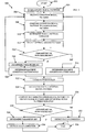
- FIG. 5 is a flowchart of a method 500 of machine condition monitoring.
- method steps of method 500 may be used to detect fault conditions.
- Machine condition monitoring system 100 specifically pattern detection module 106 and pattern rule module 108, may be used to detect faults in machines 102.
- the method begins at step 502.
- known signal patterns are stored at pattern detection module 106.
- Known signal patterns include parametric signal patterns, such as signal pattern 202 and signal pattern 302, as well as nonparametric signal patterns, such as nonparametric signal pattern 402. Any appropriate parametric signal patterns may be stored.
- Nonparametric signal patterns indicative of fault or other significant conditions may also be stored at pattern detection module 106. In some embodiments, such nonparametric signal patterns are automatically detected and stored. In alternative embodiments, nonparametric signal patterns are identified by a user and entered into (e.g., selected by or otherwise denoted) pattern detection module 106.
- Parametric signal patterns may be stored by storing their relevant signal parameters S.
- Time templates of nonparametric signal patterns store all data point values (e.g., outputs of sensors 104) in the nonparametric signal pattern.
- a transform e.g., general wavelet transform, Fourier transform, etc.
- a condition signal pattern is received.
- a condition signal pattern is a signal pattern for which a pattern rule is to be determined.
- the condition signal pattern is received at the pattern detection module 106.
- the condition signal pattern is a signal pattern received from sensors 104 that is indicative of a fault condition. Accordingly, the condition signal pattern may be a parametric or nonparametric signal pattern.
- a user may designate the received condition signal pattern as a known fault and may submit the condition signal pattern to pattern detection module 106.
- the condition signal pattern is compared to known signal patterns stored in step 504.
- the condition signal pattern may be compared to one or more parametric signal patterns and nonparametric signal patterns. Additionally, the duration T of the condition signal pattern and/or the known signal pattern may be stretched and/or compressed to match each other to facilitate the comparison.
- Any appropriate comparison measure may be used and a matching score G may be determined.
- An individual matching score G may be determined for each comparison of the condition signal pattern to a known signal pattern.
- Matching scores G are the best values obtained using all available comparison measures. That is, the comparison measures are optimized to present the best possible fit of the condition signal pattern to the known signal patterns.
- the matching score G is thus an indication of a correlation, or match, based on the comparison measure.
- the optimal match is the minimum matching score G.
- the optimal match is the maximum matching score G.
- a signal pattern duration is determined.
- the comparison measures of step 508 are normalized by T such that they are insensitive to the variable durations of T, as discussed above.
- X T is compared with Z T using an appropriate comparison measure (e.g., a Euclidean distance, a correlation, etc.).
- the duration T of the known signal pattern may be varied to coincide with the optimal (e.g., maximum or minimum, as appropriate) comparison measure. That is, the duration T is varied to allow the comparison of the condition signal pattern to each known signal pattern to achieve the most optimal correlation.
- a fast Fourier transform or another appropriate transform may be employed to scan the whole incoming condition signal pattern in a very short time.
- downsampling e.g., reducing the sampling rate of the signal
- interpolation e.g., interpolation, and/or other appropriate methods
- step 512 the optimal known signal pattern is selected. Based on the matching score determined in step 508 and the signal pattern duration determined in step 510, the condition signal pattern is compared to each of a plurality of known signal patterns and the known signal pattern that most closely matches (as evidenced by matching score G and/or signal pattern duration T) may be selected.
- step 514 a determination is made as to whether the known signal pattern is a parametric (P) or nonparametric (NP) signal pattern. If the known signal pattern is a parametric signal pattern, the method passes to step 516 and an optimal parameter set S is determined.
- a standard least square method may be used to find an optimal matching score G.
- a gradient-based optimization method may be used to search for an optimal matching score G. Of course, any appropriate method of finding an optimal matching score G may be used.
- the parameter set S corresponding to the solution with the optimal matching score S may be considered as the optimal parameter set S.
- a machine condition pattern rule is determined by pattern rule module 108.
- the machine condition pattern rule is determined, in step 518, using the signal pattern duration T and the matching score G.
- the machine condition pattern rule is thus a multipartite threshold rule with a first threshold based on the determined matching score and the second threshold based on the determined signal pattern duration.
- the pattern rule is defined as a multi-input conditional logical rule with a duration threshold as one input and a matching score threshold as another input. For example, using a Euclidean distance measure as described above, a pattern rule may be defined as "If signal duration T > threshold A AND matching score G ⁇ threshold B, then fault type 1 occurs.”
- a machine condition pattern rule is determined in step 520 by pattern rule module 108.
- the machine condition pattern rule is determined, in step 520, using the signal pattern duration T, the matching score G, and the parameter set S.
- the machine condition pattern rule is thus a multipartite threshold rule with a first threshold based on the determined matching score, a second threshold based on the determined signal pattern duration, and a third threshold based on the one or more parameters of parameter set S.
- the pattern rule is defined as a multi-input conditional logical rule with a duration threshold as one input, a matching score threshold as another input, and a parameter set as still another input. For example, using a correlation measure as described above, a pattern rule may be defined as "If signal duration T > threshold A AND matching score G ⁇ threshold B AND slope > m, then fault type 2 occurs.”
- Method steps 506-520 may be repeated as appropriate to determine multiple pattern rules. That is, following determination of pattern rules in steps 518 and/or 520, the method 500 may return control to step 506. These pattern rules may be stored after steps 518 and/or 520 in a rule base (not shown) in step 522.
- a machine condition signal is received from sensors 104 at pattern detection module 106 or another pattern rules processing location.
- the machine condition signal may comprise a machine condition signal pattern as described above with respect to FIGS. 2-4 and may be indicative of machine parameters of machine 102.
- the machine condition signal pattern may be a parametric signal pattern or a nonparametric signal pattern.
- a duration of the machine condition signal pattern is determined and the received machine condition signal pattern is compared to at least one known signal pattern.
- a duration determination may be based on a user input and/or may be based at least in part on the signal values. That is, the duration may be determined based on the changes to the signal values that indicate machine condition changes.
- the received machine condition signal pattern is compared to at least one known signal pattern. Such a comparison may similar to the comparison of step 508 described above and may include a determination of a matching score G.
- step 528 a determination is made as to whether the received machine condition signal pattern is a parametric or nonparametric signal pattern. If the received machine condition signal pattern is a parametric signal pattern, the method passes to step 530 and a parameter set S of the received machine condition signal pattern is determined. If the received machine condition signal pattern is a nonparametric signal pattern, the method passes to step 532.
- nonparametric rules in the rule base are used to detect a fault condition in step 532.
- parametric rules in the rule base are used to detect a fault condition in step 534.
- the signal pattern duration T, matching score, and, in the case or parametric signal patterns, the parameter set S are input to the pattern rules stored in method step 522 to detect a fault condition. In this way, a fault condition is detected if the machine condition signal pattern satisfies one or more properties of the determined machine condition pattern rule.
- the method ends at step 536.
- FIG. 6 is a schematic drawing of a computer 600 according to an embodiment of the invention.
- Computer 600 may be used in conjunction with and/or may perform the functions of machine condition monitoring system 100 and/or the method steps of method 500.
- Computer 600 contains a processor 602 that controls the overall operation of the computer 600 by executing computer program instructions, which define such operation.
- the computer program instructions may be stored in a storage device 604 (e.g., magnetic disk, database, etc.) and loaded into memory 606 when execution of the computer program instructions is desired.
- applications for performing the herein-described method steps, such as pattern rule creation, fault detection, and machine condition monitoring, in method 500 are defined by the computer program instructions stored in the memory 606 and/or storage 604 and controlled by the processor 602 executing the computer program instructions.
- the computer 600 may also include one or more network interfaces 608 for communicating with other devices via a network.
- the computer 600 also includes input/output devices 610 (e.g., display, keyboard, mouse, speakers, buttons, etc.) that enable user interaction with the computer 600.
- Computer 600 and/or processor 602 may include one or more central processing units, read only memory (ROM) devices and/or random access memory (RAM) devices.
- ROM read only memory
- RAM random access memory
- instructions of a program may be read into memory 606, such as from a ROM device to a RAM device or from a LAN adapter to a RAM device. Execution of sequences of the instructions in the program may cause the computer 600 to perform one or more of the method steps described herein, such as those described above with respect to method 500.
- hard-wired circuitry or integrated circuits may be used in place of, or in combination with, software instructions for implementation of the processes of the present invention.
- embodiments of the present invention are not limited to any specific combination of hardware, firmware, and/or software.
- the memory 606 may store the software for the computer 600, which may be adapted to execute the software program and thereby operate in accordance with the present invention and particularly in accordance with the methods described in detail above.
- the invention as described herein could be implemented in many different ways using a wide range of programming techniques as well as general purpose hardware sub-systems or dedicated controllers.
- Such programs may be stored in a compressed, uncompiled, and/or encrypted format.
- the programs furthermore may include program elements that may be generally useful, such as an operating system, a database management system, and device drivers for allowing the controller to interface with computer peripheral devices, and other equipment/components.
- Appropriate general purpose program elements are known to those skilled in the art, and need not be described in detail herein.
Landscapes
- Engineering & Computer Science (AREA)
- Life Sciences & Earth Sciences (AREA)
- Bioinformatics & Cheminformatics (AREA)
- Bioinformatics & Computational Biology (AREA)
- Evolutionary Biology (AREA)
- Physics & Mathematics (AREA)
- General Physics & Mathematics (AREA)
- Automation & Control Theory (AREA)
- Testing And Monitoring For Control Systems (AREA)
Claims (10)
- Verfahren zur Maschinenzustand-Überwachung durch einen Prozessor (602) eines Maschinenzustand-Überwachungssystems (100, 600), das Verfahren umfassend:Empfangen (506) eines Zustandssignalmusters von Sensoren, die Parameter einer überwachten Maschine (102) messen, wobei das Zustandssignalmuster indikativ für einen Fehlerzustand ist;Vergleichen (508) des Zustandssignalmusters (102) mit einer Vielzahl bekannter Signalmuster, die indikativ für Fehlerzustände sind;Erzeugen einer Maschinenzustand-Musterregel für die überwachte Maschine (102) basierend auf dem Vergleich des Zustandssignalmusters mit jedem der Vielzahl von bekannten Signalmustern, wobei ein Erzeugen einer Maschinenzustand-Musterregel Folgendes umfasst:Bestimmen eines Übereinstimmungswerts für jeden Vergleich des Zustandssignalmusters mit jedem der Vielzahl bekannter Signalmuster basierend auf dem Vergleichs des Zustandssignalmusters mit jedem der Vielzahl bekannter Signalmuster;Bestimmen (510) einer Signalmusterdauer von jedem der Vielzahl bekannter Signalmuster durch Variieren der ursprünglichen Signalmusterdauer von jedem der Vielzahl bekannter Signalmuster, um eine optimale Korrelation mit dem Zustandssignalmuster zu erreichen;Bestimmen (512) eines optimalen bekannten Signalmusters basierend auf den Übereinstimmungswerten und den Signalmusterdauern, wobei das bekannte Signalmuster, das am ehesten mit dem Zustandssignalmuster übereinstimmt, als das optimale bekannte Signalmuster ausgewählt wird;Definieren (516, 518) der Maschinenzustand-Musterregel als eine mehrteilige Schwellenwertregel mit einem ersten Schwellenwert basierend auf dem ermittelten Übereinstimmungswert des optimalen bekannten Signalmusters, und einem zweiten Schwellenwert basierend auf der ermittelten Signalmusterdauer des optimalen bekannten Signalmusters;Speichern (522) der erzeugten Maschinenzustand-Musterregel in einer Regelbasis des Maschinenzustand-Überwachungssystems (100, 600); undÜberwachen eines Maschinenzustands der überwachten Maschine (102) durch Erfassen (532, 534) eines Fehlerzustands in der überwachten Maschine basierend auf einem Maschinenzustandssignal, das von der überwachten Maschine unter Verwendung der erzeugten Maschinenzustand-Musterregel empfangen wird.
- Verfahren gemäß Anspruch 1, wobei ein Überwachen eines Maschinenzustands der überwachten Maschine Folgendes umfasst:Empfang des Maschinenzustandssignals einschließlich eines Maschinenzustand-Signalmusters von den Sensoren, die die Parameter der überwachten Maschine messen;Bestimmen, ob das Maschinenzustand-Signalmuster eine oder mehrere Eigenschaften der erzeugten Maschinenzustand-Musterregel erfüllt.
- Verfahren gemäß Anspruch 1, wobei ein Erzeugen einer Maschinenzustand-Musterregel ferner Folgendes umfasst:Bestimmen, ob das optimale bekannte Signalmuster ein parametrisches Signalmuster oder ein nicht-parametrisches Signalmuster ist; undDefinieren (518) der Maschinenzustand-Musterregel als mehrteilige Schwellenwertregel mit einem zusätzlichen dritten Schwellenwert basierend auf einem optimalen Parametersatz des optimalen bekannten Signalmusters, wenn das optimale bekannte Signalmuster ein parametrisches Signalmuster ist.
- Verfahren gemäß Anspruch 1, wobei das Bestimmen der Signalmusterdauer von jedem der Vielzahl bekannter Signalmuster zum Erreichen einer optimalen Korrelation mit dem Zustandssignalmuster Folgendes umfasst:
Ausdehnen oder Komprimieren der ursprünglichen Signalmusterdauer von jedem der Vielzahl bekannter Signalmuster, um eine optimale Korrelation mit dem Zustandssignalmuster zu erreichen. - Verfahren gemäß Anspruch 1, wobei das Bestimmen der Signalmusterdauer von jedem der Vielzahl bekannter Signalmuster zum Erreichen einer optimalen Korrelation mit dem Zustandssignalmuster Folgendes umfasst:
Variieren der ursprünglichen Signalmusterdauer von jedem der Vielzahl bekannter Signalmuster unter Aufrechterhaltung einer Dauer des Zustandssignalmusters, um eine optimale Korrelation mit dem Zustandssignalmuster zu erreichen. - Verfahren gemäß Anspruch 1, wobei, wenn die Vielzahl bekannter Signalmuster nicht-parametrische Signalmuster sind, das Bestimmen der Signalmusterdauer von jedem der Vielzahl bekannter Signalmuster zum Erreichen einer optimalen Korrelation mit dem Zustandssignalmuster Folgendes umfasst:
Variieren der ursprünglichen Signalmusterdauer von jedem der Vielzahl bekannter Signalmuster unter Verwendung von Abwärtsabtastung oder Interpolation zum Bestimmen von Signalwerten an nicht vorhandenen Datenpunkten. - Datenverarbeitungsvorrichtung zur Maschinenzustandsüberwachung, umfassend:Einrichtung (106) zum Empfangen eines Zustandssignalmusters von Sensoren, die Parameter einer überwachten Maschine (102) messen, wobei das Zustandssignalmuster indikativ für einen Fehlerzustand ist;Einrichtung zum Vergleichen des Zustandssignalmusters mit einer Vielzahl bekannter Signalmuster, die indikativ für Fehlerzustände sind;Einrichtung zum Erzeugen einer Maschinenzustand-Musterregel für die überwachte Maschine basierend auf dem Vergleich des Zustandssignalmusters mit jedem der Vielzahl bekannter Signalmuster, wobei die Einrichtung zum Erzeugen einer Maschinenzustand-Musterregel Folgendes umfasst:Einrichtung zum Bestimmen eines Übereinstimmungswerts für jeden Vergleich des Zustandssignalmusters mit jedem der Vielzahl bekannter Signalmuster basierend auf dem Vergleichs des Zustandssignalmusters mit jedem der Vielzahl bekannter Signalmuster;Einrichtung zum Bestimmen einer Signalmusterdauer von jedem der Vielzahl bekannter Signalmuster durch Variieren der ursprünglichen Signalmusterdauer von jedem der Vielzahl bekannter Signalmuster, um eine optimale Korrelation mit dem Zustandssignalmuster zu erreichen;Einrichtung zum Bestimmen eines optimalen bekannten Signalmusters basierend auf den Übereinstimmungswerten und den Signalmusterdauern, wobei das bekannte Signalmuster, das am ehesten mit dem Zustandssignalmuster übereinstimmt, als das optimale bekannte Signalmuster ausgewählt wird; undEinrichtung zum Definieren der Maschinenzustand-Musterregel als eine mehrteilige Schwellenwertregel mit einem ersten Schwellenwert basierend auf dem ermittelten Übereinstimmungswert des optimalen bekannten Signalmusters, und einem zweiten Schwellenwert basierend auf der ermittelten Signalmusterdauer des optimalen bekannten Signalmusters;Einrichtung zum Speichern der erzeugten Maschinenzustand-Musterregel in einer Regelbasis; undEinrichtung zum Überwachen eines Maschinenzustands der überwachten Maschine durch Erfassen eines Fehlerzustands in der überwachten Maschine basierend auf einem Maschinenzustandssignal, das von der überwachten Maschine unter Verwendung der erzeugten Maschinenzustand-Musterregel empfangen wird.
- Datenverarbeitungsvorrichtung gemäß Anspruch 8, wobei die Einrichtung zum Überwachen des Maschinenzustands der überwachten Maschine Folgendes umfasst:Einrichtung zum Empfangen des Maschinenzustandssignals einschließlich eines Maschinenzustand-Signalmusters von den Sensoren, die die Parameter der überwachten Maschine messen;Einrichtung zum Bestimmen, ob das Maschinenzustand-Signalmuster eine oder mehrere Eigenschaften der erzeugten Maschinenzustand-Musterregel erfüllt.
- Datenverarbeitungsvorrichtung gemäß Anspruch 7, wobei die Einrichtung zum Erzeugen einer Maschinenzustand-Musterregel ferner Folgendes umfasst:Einrichtung zum Bestimmen, ob das optimale bekannte Signalmuster ein parametrisches Signalmuster oder ein nicht-parametrisches Signalmuster ist; undEinrichtung zum Definieren der Maschinenzustand-Musterregel als mehrteilige Schwellenwertregel mit einem zusätzlichen dritten Schwellenwert basierend auf einem optimalen Parametersatz des optimalen bekannten Signalmusters, wenn das optimale bekannte Signalmuster ein parametrisches Signalmuster ist.
- Maschinenlesbarer Datenträger mit darauf gespeicherten Programmanweisungen, die, wenn sie von einem Prozessor ausgeführt werden, den Prozessor veranlassen, das Verfahren nach einem der Ansprüche 1 bis 6 auszuführen.
Applications Claiming Priority (3)
| Application Number | Priority Date | Filing Date | Title |
|---|---|---|---|
| US91157707P | 2007-04-13 | 2007-04-13 | |
| US12/077,279 US20080255773A1 (en) | 2007-04-13 | 2008-03-18 | Machine condition monitoring using pattern rules |
| PCT/US2008/003642 WO2008127535A1 (en) | 2007-04-13 | 2008-03-20 | Machine condition monitoring using pattern rules |
Publications (2)
| Publication Number | Publication Date |
|---|---|
| EP2135144A1 EP2135144A1 (de) | 2009-12-23 |
| EP2135144B1 true EP2135144B1 (de) | 2020-08-26 |
Family
ID=39854506
Family Applications (1)
| Application Number | Title | Priority Date | Filing Date |
|---|---|---|---|
| EP08742146.7A Active EP2135144B1 (de) | 2007-04-13 | 2008-03-20 | Maschinenzustandsüberwachung mithilfe von musterregeln |
Country Status (4)
| Country | Link |
|---|---|
| US (1) | US20080255773A1 (de) |
| EP (1) | EP2135144B1 (de) |
| CN (1) | CN101681163B (de) |
| WO (1) | WO2008127535A1 (de) |
Families Citing this family (8)
| Publication number | Priority date | Publication date | Assignee | Title |
|---|---|---|---|---|
| US8112381B2 (en) * | 2007-11-02 | 2012-02-07 | Siemens Corporation | Multivariate analysis of wireless sensor network data for machine condition monitoring |
| US8489363B2 (en) * | 2010-09-28 | 2013-07-16 | General Electric Company | Monitoring and diagnosing generator operation |
| US8849472B2 (en) * | 2011-02-02 | 2014-09-30 | Inscope Energy, Llc | Effectuating energization and deactivation of particular circuits through rules-based smart nodes |
| DE102012001083A1 (de) * | 2012-01-20 | 2013-07-25 | Heidelberger Druckmaschinen Ag | Dynamisches Logfile |
| US20140244192A1 (en) * | 2013-02-25 | 2014-08-28 | Inscope Energy, Llc | System and method for providing monitoring of industrial equipment |
| US10205733B1 (en) * | 2015-06-17 | 2019-02-12 | Mission Secure, Inc. | Cyber signal isolator |
| US10250619B1 (en) | 2015-06-17 | 2019-04-02 | Mission Secure, Inc. | Overlay cyber security networked system and method |
| JP7101131B2 (ja) * | 2019-01-31 | 2022-07-14 | ファナック株式会社 | 数値制御システム |
Citations (2)
| Publication number | Priority date | Publication date | Assignee | Title |
|---|---|---|---|---|
| US6076405A (en) * | 1994-08-31 | 2000-06-20 | Honeywell International Inc. | Remote self-powered structure monitor |
| US6484109B1 (en) * | 1998-05-20 | 2002-11-19 | Dli Engineering Coporation | Diagnostic vibration data collector and analyzer |
Family Cites Families (9)
| Publication number | Priority date | Publication date | Assignee | Title |
|---|---|---|---|---|
| JPS56130634A (en) * | 1980-03-19 | 1981-10-13 | Hitachi Ltd | Method and device for monitoring oscillation of rotary machine |
| US4348553A (en) * | 1980-07-02 | 1982-09-07 | International Business Machines Corporation | Parallel pattern verifier with dynamic time warping |
| US5041976A (en) * | 1989-05-18 | 1991-08-20 | Ford Motor Company | Diagnostic system using pattern recognition for electronic automotive control systems |
| US5210704A (en) * | 1990-10-02 | 1993-05-11 | Technology International Incorporated | System for prognosis and diagnostics of failure and wearout monitoring and for prediction of life expectancy of helicopter gearboxes and other rotating equipment |
| US5566092A (en) * | 1993-12-30 | 1996-10-15 | Caterpillar Inc. | Machine fault diagnostics system and method |
| US6105015A (en) * | 1997-02-03 | 2000-08-15 | The United States Of America As Represented By The Secretary Of The Navy | Wavelet-based hybrid neurosystem for classifying a signal or an image represented by the signal in a data system |
| US6539343B2 (en) * | 2000-02-03 | 2003-03-25 | Xerox Corporation | Methods for condition monitoring and system-level diagnosis of electro-mechanical systems with multiple actuating components operating in multiple regimes |
| US6877107B2 (en) * | 2001-07-05 | 2005-04-05 | Softwired Ag | Method for ensuring operation during node failures and network partitions in a clustered message passing server |
| US6816816B2 (en) * | 2003-02-12 | 2004-11-09 | Bently Nevada, Llc | Transducer fault detection system using slew rate measurements: apparatus and method |
-
2008
- 2008-03-18 US US12/077,279 patent/US20080255773A1/en not_active Abandoned
- 2008-03-20 CN CN200880011864.6A patent/CN101681163B/zh active Active
- 2008-03-20 EP EP08742146.7A patent/EP2135144B1/de active Active
- 2008-03-20 WO PCT/US2008/003642 patent/WO2008127535A1/en not_active Ceased
Patent Citations (2)
| Publication number | Priority date | Publication date | Assignee | Title |
|---|---|---|---|---|
| US6076405A (en) * | 1994-08-31 | 2000-06-20 | Honeywell International Inc. | Remote self-powered structure monitor |
| US6484109B1 (en) * | 1998-05-20 | 2002-11-19 | Dli Engineering Coporation | Diagnostic vibration data collector and analyzer |
Also Published As
| Publication number | Publication date |
|---|---|
| WO2008127535A1 (en) | 2008-10-23 |
| EP2135144A1 (de) | 2009-12-23 |
| US20080255773A1 (en) | 2008-10-16 |
| CN101681163A (zh) | 2010-03-24 |
| CN101681163B (zh) | 2015-02-25 |
Similar Documents
| Publication | Publication Date | Title |
|---|---|---|
| EP2135144B1 (de) | Maschinenzustandsüberwachung mithilfe von musterregeln | |
| US20230080171A1 (en) | Systems and methods for monitoring of mechanical and electrical machines | |
| US9122273B2 (en) | Failure cause diagnosis system and method | |
| US12332111B2 (en) | Autonomous discrimination of operation vibration signals | |
| CN112272763B (zh) | 异常探测装置、异常探测方法以及计算机可读取的存储介质 | |
| US10496466B2 (en) | Preprocessor of abnormality sign diagnosing device and processing method of the same | |
| EP3674827B1 (de) | Vorrichtung zur auswahl eines überwachungsziels, verfahren zur auswahl eines überwachungsziels und programm | |
| US20130060524A1 (en) | Machine Anomaly Detection and Diagnosis Incorporating Operational Data | |
| CN116593811A (zh) | 一种集成型变频器运行状态监测系统及监测方法 | |
| US20200143292A1 (en) | Signature enhancement for deviation measurement-based classification of a detected anomaly in an industrial asset | |
| US10032322B2 (en) | Validation tool for an aircraft engine monitoring system | |
| US7949497B2 (en) | Machine condition monitoring using discontinuity detection | |
| CN116226719A (zh) | 基于多维稳态振动特征的轴承故障诊断方法及相关组件 | |
| CN114490829B (zh) | 一种故障识别方法、装置、设备及存储介质 | |
| JPWO2004068078A1 (ja) | 状態判定方法と状態予測方法及び装置 | |
| US7366639B2 (en) | Methods for establishing alerts and/or alert limits for monitoring mechanical devices | |
| US8762080B2 (en) | Computer component detection system and method | |
| US11339763B2 (en) | Method for windmill farm monitoring | |
| CN118536409B (zh) | 基于修正预测的发电机转子绕组闸间短路预测方法及系统 | |
| EP4254111A1 (de) | Fehlerdiagnosevorrichtung, verfahren, computerprogramm und nichtflüchtiges computerlesbares aufzeichnungsmedium | |
| WO2020054725A1 (ja) | 診断装置及び診断方法 | |
| WO2024120018A1 (zh) | 检测方法、训练方法、电器、监控系统、存储介质和设备 | |
| CN116861356A (zh) | 异常数据检测方法及装置、电子设备、存储介质 | |
| JP2020009325A (ja) | 異常検知プログラム、異常検知方法及び異常検知装置 | |
| CN114819173B (zh) | 异常侦测装置和异常侦测方法 |
Legal Events
| Date | Code | Title | Description |
|---|---|---|---|
| PUAI | Public reference made under article 153(3) epc to a published international application that has entered the european phase |
Free format text: ORIGINAL CODE: 0009012 |
|
| 17P | Request for examination filed |
Effective date: 20090921 |
|
| AK | Designated contracting states |
Kind code of ref document: A1 Designated state(s): AT BE BG CH CY CZ DE DK EE ES FI FR GB GR HR HU IE IS IT LI LT LU LV MC MT NL NO PL PT RO SE SI SK TR |
|
| RIN1 | Information on inventor provided before grant (corrected) |
Inventor name: NEUBAUER, CLAUS Inventor name: HACKSTEIN, HOLGER Inventor name: YUAN, CHAO |
|
| DAX | Request for extension of the european patent (deleted) | ||
| RAP1 | Party data changed (applicant data changed or rights of an application transferred) |
Owner name: SIEMENS AKTIENGESELLSCHAFT Owner name: SIEMENS CORPORATION |
|
| RAP1 | Party data changed (applicant data changed or rights of an application transferred) |
Owner name: SIEMENS CORPORATION Owner name: SIEMENS AKTIENGESELLSCHAFT |
|
| 17Q | First examination report despatched |
Effective date: 20151023 |
|
| STAA | Information on the status of an ep patent application or granted ep patent |
Free format text: STATUS: EXAMINATION IS IN PROGRESS |
|
| RAP1 | Party data changed (applicant data changed or rights of an application transferred) |
Owner name: SIEMENS CORPORATION Owner name: SIEMENS AKTIENGESELLSCHAFT |
|
| GRAP | Despatch of communication of intention to grant a patent |
Free format text: ORIGINAL CODE: EPIDOSNIGR1 |
|
| STAA | Information on the status of an ep patent application or granted ep patent |
Free format text: STATUS: GRANT OF PATENT IS INTENDED |
|
| INTG | Intention to grant announced |
Effective date: 20200417 |
|
| RAP1 | Party data changed (applicant data changed or rights of an application transferred) |
Owner name: SIEMENS AKTIENGESELLSCHAFT |
|
| GRAS | Grant fee paid |
Free format text: ORIGINAL CODE: EPIDOSNIGR3 |
|
| GRAA | (expected) grant |
Free format text: ORIGINAL CODE: 0009210 |
|
| STAA | Information on the status of an ep patent application or granted ep patent |
Free format text: STATUS: THE PATENT HAS BEEN GRANTED |
|
| AK | Designated contracting states |
Kind code of ref document: B1 Designated state(s): AT BE BG CH CY CZ DE DK EE ES FI FR GB GR HR HU IE IS IT LI LT LU LV MC MT NL NO PL PT RO SE SI SK TR |
|
| REG | Reference to a national code |
Ref country code: GB Ref legal event code: FG4D |
|
| REG | Reference to a national code |
Ref country code: CH Ref legal event code: EP |
|
| REG | Reference to a national code |
Ref country code: AT Ref legal event code: REF Ref document number: 1306947 Country of ref document: AT Kind code of ref document: T Effective date: 20200915 |
|
| REG | Reference to a national code |
Ref country code: IE Ref legal event code: FG4D |
|
| REG | Reference to a national code |
Ref country code: DE Ref legal event code: R096 Ref document number: 602008063179 Country of ref document: DE |
|
| REG | Reference to a national code |
Ref country code: CH Ref legal event code: NV Representative=s name: SIEMENS SCHWEIZ AG, CH |
|
| REG | Reference to a national code |
Ref country code: LT Ref legal event code: MG4D |
|
| PG25 | Lapsed in a contracting state [announced via postgrant information from national office to epo] |
Ref country code: HR Free format text: LAPSE BECAUSE OF FAILURE TO SUBMIT A TRANSLATION OF THE DESCRIPTION OR TO PAY THE FEE WITHIN THE PRESCRIBED TIME-LIMIT Effective date: 20200826 Ref country code: BG Free format text: LAPSE BECAUSE OF FAILURE TO SUBMIT A TRANSLATION OF THE DESCRIPTION OR TO PAY THE FEE WITHIN THE PRESCRIBED TIME-LIMIT Effective date: 20201126 Ref country code: SE Free format text: LAPSE BECAUSE OF FAILURE TO SUBMIT A TRANSLATION OF THE DESCRIPTION OR TO PAY THE FEE WITHIN THE PRESCRIBED TIME-LIMIT Effective date: 20200826 Ref country code: FI Free format text: LAPSE BECAUSE OF FAILURE TO SUBMIT A TRANSLATION OF THE DESCRIPTION OR TO PAY THE FEE WITHIN THE PRESCRIBED TIME-LIMIT Effective date: 20200826 Ref country code: GR Free format text: LAPSE BECAUSE OF FAILURE TO SUBMIT A TRANSLATION OF THE DESCRIPTION OR TO PAY THE FEE WITHIN THE PRESCRIBED TIME-LIMIT Effective date: 20201127 Ref country code: NO Free format text: LAPSE BECAUSE OF FAILURE TO SUBMIT A TRANSLATION OF THE DESCRIPTION OR TO PAY THE FEE WITHIN THE PRESCRIBED TIME-LIMIT Effective date: 20201126 Ref country code: PT Free format text: LAPSE BECAUSE OF FAILURE TO SUBMIT A TRANSLATION OF THE DESCRIPTION OR TO PAY THE FEE WITHIN THE PRESCRIBED TIME-LIMIT Effective date: 20201228 Ref country code: LT Free format text: LAPSE BECAUSE OF FAILURE TO SUBMIT A TRANSLATION OF THE DESCRIPTION OR TO PAY THE FEE WITHIN THE PRESCRIBED TIME-LIMIT Effective date: 20200826 |
|
| REG | Reference to a national code |
Ref country code: NL Ref legal event code: MP Effective date: 20200826 |
|
| PG25 | Lapsed in a contracting state [announced via postgrant information from national office to epo] |
Ref country code: LV Free format text: LAPSE BECAUSE OF FAILURE TO SUBMIT A TRANSLATION OF THE DESCRIPTION OR TO PAY THE FEE WITHIN THE PRESCRIBED TIME-LIMIT Effective date: 20200826 Ref country code: NL Free format text: LAPSE BECAUSE OF FAILURE TO SUBMIT A TRANSLATION OF THE DESCRIPTION OR TO PAY THE FEE WITHIN THE PRESCRIBED TIME-LIMIT Effective date: 20200826 Ref country code: PL Free format text: LAPSE BECAUSE OF FAILURE TO SUBMIT A TRANSLATION OF THE DESCRIPTION OR TO PAY THE FEE WITHIN THE PRESCRIBED TIME-LIMIT Effective date: 20200826 Ref country code: IS Free format text: LAPSE BECAUSE OF FAILURE TO SUBMIT A TRANSLATION OF THE DESCRIPTION OR TO PAY THE FEE WITHIN THE PRESCRIBED TIME-LIMIT Effective date: 20201226 |
|
| PG25 | Lapsed in a contracting state [announced via postgrant information from national office to epo] |
Ref country code: RO Free format text: LAPSE BECAUSE OF FAILURE TO SUBMIT A TRANSLATION OF THE DESCRIPTION OR TO PAY THE FEE WITHIN THE PRESCRIBED TIME-LIMIT Effective date: 20200826 Ref country code: DK Free format text: LAPSE BECAUSE OF FAILURE TO SUBMIT A TRANSLATION OF THE DESCRIPTION OR TO PAY THE FEE WITHIN THE PRESCRIBED TIME-LIMIT Effective date: 20200826 Ref country code: EE Free format text: LAPSE BECAUSE OF FAILURE TO SUBMIT A TRANSLATION OF THE DESCRIPTION OR TO PAY THE FEE WITHIN THE PRESCRIBED TIME-LIMIT Effective date: 20200826 Ref country code: CZ Free format text: LAPSE BECAUSE OF FAILURE TO SUBMIT A TRANSLATION OF THE DESCRIPTION OR TO PAY THE FEE WITHIN THE PRESCRIBED TIME-LIMIT Effective date: 20200826 |
|
| REG | Reference to a national code |
Ref country code: DE Ref legal event code: R097 Ref document number: 602008063179 Country of ref document: DE |
|
| PG25 | Lapsed in a contracting state [announced via postgrant information from national office to epo] |
Ref country code: ES Free format text: LAPSE BECAUSE OF FAILURE TO SUBMIT A TRANSLATION OF THE DESCRIPTION OR TO PAY THE FEE WITHIN THE PRESCRIBED TIME-LIMIT Effective date: 20200826 |
|
| PG25 | Lapsed in a contracting state [announced via postgrant information from national office to epo] |
Ref country code: SK Free format text: LAPSE BECAUSE OF FAILURE TO SUBMIT A TRANSLATION OF THE DESCRIPTION OR TO PAY THE FEE WITHIN THE PRESCRIBED TIME-LIMIT Effective date: 20200826 |
|
| PLBE | No opposition filed within time limit |
Free format text: ORIGINAL CODE: 0009261 |
|
| STAA | Information on the status of an ep patent application or granted ep patent |
Free format text: STATUS: NO OPPOSITION FILED WITHIN TIME LIMIT |
|
| 26N | No opposition filed |
Effective date: 20210527 |
|
| PG25 | Lapsed in a contracting state [announced via postgrant information from national office to epo] |
Ref country code: SI Free format text: LAPSE BECAUSE OF FAILURE TO SUBMIT A TRANSLATION OF THE DESCRIPTION OR TO PAY THE FEE WITHIN THE PRESCRIBED TIME-LIMIT Effective date: 20200826 |
|
| PG25 | Lapsed in a contracting state [announced via postgrant information from national office to epo] |
Ref country code: MC Free format text: LAPSE BECAUSE OF FAILURE TO SUBMIT A TRANSLATION OF THE DESCRIPTION OR TO PAY THE FEE WITHIN THE PRESCRIBED TIME-LIMIT Effective date: 20200826 |
|
| REG | Reference to a national code |
Ref country code: BE Ref legal event code: MM Effective date: 20210331 |
|
| PG25 | Lapsed in a contracting state [announced via postgrant information from national office to epo] |
Ref country code: FR Free format text: LAPSE BECAUSE OF NON-PAYMENT OF DUE FEES Effective date: 20210331 Ref country code: IE Free format text: LAPSE BECAUSE OF NON-PAYMENT OF DUE FEES Effective date: 20210320 Ref country code: LU Free format text: LAPSE BECAUSE OF NON-PAYMENT OF DUE FEES Effective date: 20210320 |
|
| PG25 | Lapsed in a contracting state [announced via postgrant information from national office to epo] |
Ref country code: BE Free format text: LAPSE BECAUSE OF NON-PAYMENT OF DUE FEES Effective date: 20210331 |
|
| REG | Reference to a national code |
Ref country code: AT Ref legal event code: UEP Ref document number: 1306947 Country of ref document: AT Kind code of ref document: T Effective date: 20200826 |
|
| PG25 | Lapsed in a contracting state [announced via postgrant information from national office to epo] |
Ref country code: HU Free format text: LAPSE BECAUSE OF FAILURE TO SUBMIT A TRANSLATION OF THE DESCRIPTION OR TO PAY THE FEE WITHIN THE PRESCRIBED TIME-LIMIT; INVALID AB INITIO Effective date: 20080320 Ref country code: CY Free format text: LAPSE BECAUSE OF FAILURE TO SUBMIT A TRANSLATION OF THE DESCRIPTION OR TO PAY THE FEE WITHIN THE PRESCRIBED TIME-LIMIT Effective date: 20200826 |
|
| PG25 | Lapsed in a contracting state [announced via postgrant information from national office to epo] |
Ref country code: TR Free format text: LAPSE BECAUSE OF FAILURE TO SUBMIT A TRANSLATION OF THE DESCRIPTION OR TO PAY THE FEE WITHIN THE PRESCRIBED TIME-LIMIT Effective date: 20200826 |
|
| PG25 | Lapsed in a contracting state [announced via postgrant information from national office to epo] |
Ref country code: MT Free format text: LAPSE BECAUSE OF FAILURE TO SUBMIT A TRANSLATION OF THE DESCRIPTION OR TO PAY THE FEE WITHIN THE PRESCRIBED TIME-LIMIT Effective date: 20200826 |
|
| PGFP | Annual fee paid to national office [announced via postgrant information from national office to epo] |
Ref country code: CH Payment date: 20250401 Year of fee payment: 18 |
|
| REG | Reference to a national code |
Ref country code: CH Ref legal event code: U11 Free format text: ST27 STATUS EVENT CODE: U-0-0-U10-U11 (AS PROVIDED BY THE NATIONAL OFFICE) Effective date: 20260401 |
|
| PGFP | Annual fee paid to national office [announced via postgrant information from national office to epo] |
Ref country code: GB Payment date: 20260323 Year of fee payment: 19 |
|
| PGFP | Annual fee paid to national office [announced via postgrant information from national office to epo] |
Ref country code: DE Payment date: 20260320 Year of fee payment: 19 |
|
| PGFP | Annual fee paid to national office [announced via postgrant information from national office to epo] |
Ref country code: AT Payment date: 20260318 Year of fee payment: 19 |
|
| PGFP | Annual fee paid to national office [announced via postgrant information from national office to epo] |
Ref country code: IT Payment date: 20260320 Year of fee payment: 19 |