EP2135540A1 - Machine de nettoyage du sol - Google Patents
Machine de nettoyage du sol Download PDFInfo
- Publication number
- EP2135540A1 EP2135540A1 EP08011059A EP08011059A EP2135540A1 EP 2135540 A1 EP2135540 A1 EP 2135540A1 EP 08011059 A EP08011059 A EP 08011059A EP 08011059 A EP08011059 A EP 08011059A EP 2135540 A1 EP2135540 A1 EP 2135540A1
- Authority
- EP
- European Patent Office
- Prior art keywords
- squeegee
- cleaning machine
- floor cleaning
- dirt
- cleaned
- Prior art date
- Legal status (The legal status is an assumption and is not a legal conclusion. Google has not performed a legal analysis and makes no representation as to the accuracy of the status listed.)
- Granted
Links
Images



Classifications
-
- A—HUMAN NECESSITIES
- A47—FURNITURE; DOMESTIC ARTICLES OR APPLIANCES; COFFEE MILLS; SPICE MILLS; SUCTION CLEANERS IN GENERAL
- A47L—DOMESTIC WASHING OR CLEANING; SUCTION CLEANERS IN GENERAL
- A47L11/00—Machines for cleaning floors, carpets, furniture, walls, or wall coverings
- A47L11/29—Floor-scrubbing machines characterised by means for taking-up dirty liquid
- A47L11/30—Floor-scrubbing machines characterised by means for taking-up dirty liquid by suction
-
- A—HUMAN NECESSITIES
- A47—FURNITURE; DOMESTIC ARTICLES OR APPLIANCES; COFFEE MILLS; SPICE MILLS; SUCTION CLEANERS IN GENERAL
- A47L—DOMESTIC WASHING OR CLEANING; SUCTION CLEANERS IN GENERAL
- A47L11/00—Machines for cleaning floors, carpets, furniture, walls, or wall coverings
- A47L11/40—Parts or details of machines not provided for in groups A47L11/02 - A47L11/38, or not restricted to one of these groups, e.g. handles, arrangements of switches, skirts, buffers, levers
- A47L11/4013—Contaminants collecting devices, i.e. hoppers, tanks or the like
-
- A—HUMAN NECESSITIES
- A47—FURNITURE; DOMESTIC ARTICLES OR APPLIANCES; COFFEE MILLS; SPICE MILLS; SUCTION CLEANERS IN GENERAL
- A47L—DOMESTIC WASHING OR CLEANING; SUCTION CLEANERS IN GENERAL
- A47L11/00—Machines for cleaning floors, carpets, furniture, walls, or wall coverings
- A47L11/40—Parts or details of machines not provided for in groups A47L11/02 - A47L11/38, or not restricted to one of these groups, e.g. handles, arrangements of switches, skirts, buffers, levers
- A47L11/4027—Filtering or separating contaminants or debris
-
- A—HUMAN NECESSITIES
- A47—FURNITURE; DOMESTIC ARTICLES OR APPLIANCES; COFFEE MILLS; SPICE MILLS; SUCTION CLEANERS IN GENERAL
- A47L—DOMESTIC WASHING OR CLEANING; SUCTION CLEANERS IN GENERAL
- A47L11/00—Machines for cleaning floors, carpets, furniture, walls, or wall coverings
- A47L11/40—Parts or details of machines not provided for in groups A47L11/02 - A47L11/38, or not restricted to one of these groups, e.g. handles, arrangements of switches, skirts, buffers, levers
- A47L11/4036—Parts or details of the surface treating tools
- A47L11/4044—Vacuuming or pick-up tools; Squeegees
Definitions
- the present invention relates to a floor cleaning machine with a chassis, which is designed such that the floor cleaning machine can be moved in a direction of travel over a floor surface to be cleaned, wherein the chassis with respect to the direction of travel has a first and a second side, with a dirt collector, a squeegee disposed on the chassis above the floor surface to be cleaned and having an opening extending along the squeegee facing the floor surface, the squeegee being connected to the dirt collector via at least one conduit, a first fan being provided; producing a flow from the squeegee through the first conduit into the debris collection means, the squeegee having a first squeegee section and a second squeegee section extending from the squeegee center, the first squeegee section being the first squeegee section tt extends outwardly from the squeegee center forwardly toward the first side of the chassis, and wherein the second squeege
- Floor cleaning machines are known from the prior art, in which mounted on a chassis height adjustable, rotating driven disc brushes are provided.
- the plate brooms on a round support plate arranged bristles and are mounted on the chassis of the floor cleaning machine that they see in the direction of travel before the machine on the floor surface to be cleaned dirt in the area between the plate brooms.
- a so-called swath of dirt forms, which can be accommodated by a receiving device mounted centrally in the form of a suction mouth.
- the suction mouth is guided at a small distance above the floor surface to be cleaned and has a seen in the direction of travel forward facing opening.
- a dirt container is connected, wherein further a blower is present, through which a negative pressure is generated in the dirt container, so that an air flow from the suction mouth is formed in the dirt container, which entrains the swath.
- the squeegee is open to the floor surface to be cleaned and has a V-shape opening towards the front in the direction of travel. Furthermore, a forwardly facing opening is provided in the middle of the squeegee, which in turn can be optionally opened and closed by a closure device.
- the squeegee is connected to a dirt container via a line, and in the dirt container, a negative pressure is generated by a blower, so that dirt is sucked from the floor surface to be cleaned in the dirt container.
- blower can not be adapted solely for the extraction of particulate matter through the Saugleisten, but must also be designed to promote a large volume flow when the opening is open.
- a receiving device is provided, which is arranged adjacent to the Saugleistenmitte for receiving coarse dirt from the bottom surface to be cleaned, and that the receiving device is connected via a separately formed from the suction conveyor with the dirt collecting device.
- the Saugleistenabitese in a preferred embodiment, in particular V-shaped extending from the Saugleistenmitte seen in the direction of travel forward.
- the Saugleistenmitte is not necessarily located centrally with respect to the floor cleaning machine, but may also be laterally offset to be positioned.
- the dirt collecting device has a first dirt container and a second dirt container, wherein the suction strip with the first dirt container is connected and the conveyor with the second dirt container. In this way, the coarse dirt and fine dust can be collected separately.
- the conveying device can be designed as a screw conveyor or as a conveyor belt.
- Such conveyors are associated with the advantage that they require relatively little energy.
- the receiving device is designed as above the plane of the surface to be cleaned arranged suction nozzle, and the suction nozzle is connected to the dirt collecting device.
- the conveyor is designed as a second fan and a suction nozzle line, wherein the second fan generates an air flow from the suction nozzle into the dirt collecting device.
- the coarse dirt is conveyed pneumatically via the suction nozzle by means of an air flow in the dirt collecting device.
- the first and the second blower are independent of each other and can be adapted to the respective requirements with regard to the respectively conveyed dirt.
- the first fan may be designed such that it generates a high negative pressure in the region of the suction strips.
- the second blower is designed to promote a high flow rate, which results from the comparatively large compared to the suction strip opening cross section of the suction nozzle, which must be able to suck even larger items such as cans. Again, it does not happen that the operation of the conveyor for coarse dirt affects the suction in the area of the suction.
- rotatably driven brushes may be provided, which extend along the Saugleistenabête and can engage with the floor surface to be cleaned.
- first Saugleistenabites and the second Saugleistenabites be formed separately from each other, wherein the first Saugleistenabrough via a first line and the second Saugleistenabites are connected via a second line to the first fan.
- first squeegee portion surrounds a first interior volume and the second squeegee portion has a second interior volume, and both the first and second squeegee portions have an opening extending along the squeegee portion and facing the bottom surface to be cleaned by the particulate laden air the respective internal volume can occur.
- the Saugleistenabitese are designed to be movable independently of each other, so that an independent articulation of the Saugleistenabitese is made possible on the chassis.
- the width of the strip can be adjusted by a movable articulation of the Saugleistenabitese on the chassis, which is swept by the squeegee while driving and cleaned it.
- the Saugleistenabitese are preferably hinged to the chassis pivotally in the plane of the floor surface to be cleaned.
- a ramp element is provided in the Saugleistenmitte and seen the suction nozzle in the direction of travel is arranged behind the ramp.
- the ramp element has a forwardly facing inclined surface.
- the Saugleistenabitese can in particular be designed such that the height of the first and second Saugleistenabitess decreases to Saugleistenmitte out.
- Fig. 1 shows a perspective view of a first embodiment of a floor cleaning machine 1 according to the invention, which has a chassis with wheels 3, so that the floor cleaning machine 1 can be moved in a direction indicated by the arrow "F" driving direction over a floor surface to be cleaned.
- the chassis has seen in the direction of travel F right, first page and a left, second side.
- the floor cleaning machine 1 is designed as a self-propelled cleaning machine with a driver's cab 5 and a drive, not shown, but it is also conceivable that the floor cleaning machine 1 is pushed by an operator and not driven itself.
- a dirt collecting device 7 is arranged, which in the present embodiment comprises a first dirt container 9 and a second dirt container 11 (see Fig. 2 and 3 ).
- a Saugleistenan Aunt 13 is mounted immediately above the surface to be cleaned, which has a first Saugleistenabexcellent 15 and a second Saugleistenabites 17 includes.
- the first Saugleistenabterrorism 15 extends from the Saugleistenmitte 19 forward to the first, right side of the chassis, while the second Saugleistenabites 17 extends from the Saugleistenmitte 19 forward to the second, left side of the chassis. Therefore, the Saugleistenabête 15, 17 form in this preferred embodiment seen in the direction of travel F to the front open V-shaped arrangement.
- Saugleistenabitese 15, 17 extend in a curved shape from the Saugleistenmitte 19 to the respective sides of the chassis towards the front. In any case, however, it must be ensured that coarse dirt, which is located between the lateral outer ends of the Saugleistenabitese 15, 17, is conveyed during a movement of the floor cleaning machine 1 in the direction of travel F to Saugleistenmitte 19 out.
- the Saugleistenabitese 15, 17 have a housing which surrounds a first and second inner volume and has a along the respective Saugleistenabitess 15, 17 extending, pointing to the bottom surface to be cleaned opening.
- the first inner volume of the first Saugleistenabitess 15 is connected via a first line 21 to the first dirt container 9.
- the second inner volume of the second Saugleistenabitess 17 via a second line 23 is also connected to the first dirt container 9.
- a first fan 24 is provided, through which a negative pressure can be generated in the first dirt container 9, so that an air flow is generated by the openings provided in the Saugleistenabêten 15, 17 openings in the first dirt container 9.
- both Saugleistenabitese 15, 17 are connected to a common dirt container 9, it is also possible that the dirt container is formed in two parts. In this case, a separate part of the dirt container is provided for each Saugleistenabites.
- Fig. 2 shows, the height of the Saugleistenabitese 15, 17 for Saugleistenmitte 19 down from.
- a ramp member 25 is arranged with a forward facing inclined surface, so that coarse dirt that moves while driving the floor cleaning machine in the direction of travel F to Saugleistenmitte 19 out, can move across the squeegee 13 away.
- Saugleistenabitesen 15, 17 also support wheels 27 are provided which hold the Saugleistenabitese 15, 17 at a defined distance from the bottom surface to be cleaned.
- the Saugleistenabitese 15, 17 are further attached to a suspension 29 such that they can be pivoted on the one hand in the plane of the floor surface to be cleaned and thus change the angle at which the Saugleistenabitese 15, 17 to each other. This makes it possible to vary the width of the region of the bottom surface swept by the suction strip sections 15, 17.
- the Saugleistenabitese 15, 17 are preferably additionally pivotable in a plane which is perpendicular to the bottom surface to be cleaned, so that the Saugleistenabitese 15, 17 can also follow unevenness in the floor surface to be cleaned.
- a suction nozzle 31 is arranged for receiving coarse dirt from the bottom surface to be cleaned.
- Fig. 3 shows, the suction nozzle 31 a in the direction of travel F forward facing suction nozzle opening 32 and is connected via a suction nozzle 33 with the second dirt container 11.
- a second blower 35 is also attached, which also serves to generate a negative pressure in the second dirt container 11, so that an air flow from the suction nozzle 31 is generated in the second dirt container 11.
- the suction nozzle 31 serves as a receiving means for coarse dirt, which has run across the ramp element 25 and is located on the bottom surface to be cleaned, which is then sucked and by means of the suction nozzle 33 and the second blower 35, which serve as a conveyor in the second Dirt container 11 is promoted. Therefore, in the present embodiment, the receiving device as a suction nozzle 31 and the conveyor as a suction nozzle line 33 and fan 35 is formed.
- a mechanical promotion is provided.
- a conveyor belt or auger could be used to convey the coarse debris from the floor surface to be cleaned into the second hopper 11.
- a broom conveyor is provided as a recording and conveyor.
- the floor cleaning machine 1 moves along the direction of travel F over the floor surface to be cleaned, being sucked on this particulate matter from the Saugleistenabroughen 15, 17 and collected in the first dirt container 9.
- coarse dirt which is on the bottom surface to be cleaned is conveyed to the Saugleistenmitte 19 by the V-shaped arrangement of the Saugleistenabête 15, 17 and passes through the Saugleistenabête 15, 17 away from the opening 32 of the suction nozzle 31 and is then sucked from this and conveyed into the second dirt container 11 , Since the suction strip 15, 17 on the one hand and the receiving device in the form of the suction nozzle 31 on the other hand are operated independently of each other, the conveying of coarse dirt in the second dirt container 11 does not interfere with the suction of fine dust.
- the drive of the floor cleaning machine 1 does not have to be stopped when coarse dirt is to be absorbed.
- the level of negative pressure in the squeegee assembly 13 is affected by the promotion of coarse dirt and may collapse, which would result in areas that are not sufficiently cleaned when the floor cleaning machine is moving the negative pressure is not strong enough.
- rotatably driven brushes 39 may be provided which solve dirt and particulate matter from the bottom surface to be cleaned so that it can then be sucked through the Saugleistenan Aunt 13.
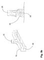
- FIGS. 4 . 5a and 5b illustrated second embodiment of a floor cleaning machine 1 'according to the invention differs from the first embodiment in that between the Saugleistenabitesen 15, 17, no ramp element 25 is arranged, but the coarse dirt can reach directly in front of the opening 32 of the suction nozzle 31.
- the inner ends of the Saugleistenabitese 15, 17 are connected to each other via a coupling element 37, so that the angle at which the Saugleistenab mustarde 15, 17 are arranged to each other, can be changed.
- Fig. 6 illustrated third embodiment differs from the second embodiment in that here the Saugleistenabitese 15, 17 are arranged such that they overlap in a movement of the floor cleaning machine 1 "in the direction of travel F areas overlap or at least directly adjacent to each other 19 facing end of the second Saugleistenabitess 17 relative to the first Saugleistenabitess 15 seen in the direction of travel F offset to the rear.
- the receiving device and the conveying device separate from the suction strip now allow the coarse dirt to be conveyed into the dirt collecting device independently of the suction strips the suction power of the suction bars is reduced and under these no sufficient negative pressure occurs, in particular to absorb particulate matter without interrupting or at least restricting particulate matter production.
Landscapes
- Cleaning In General (AREA)
- Vehicle Cleaning, Maintenance, Repair, Refitting, And Outriggers (AREA)
- Pinball Game Machines (AREA)
- Refuse-Collection Vehicles (AREA)
Priority Applications (4)
| Application Number | Priority Date | Filing Date | Title |
|---|---|---|---|
| ES08011059T ES2352651T3 (es) | 2008-06-18 | 2008-06-18 | Máquina para la limpieza de suelos. |
| EP08011059A EP2135540B1 (fr) | 2008-06-18 | 2008-06-18 | Machine de nettoyage du sol |
| DE502008001595T DE502008001595D1 (de) | 2008-06-18 | 2008-06-18 | Bodenreinigungsmaschine |
| AT08011059T ATE484993T1 (de) | 2008-06-18 | 2008-06-18 | Bodenreinigungsmaschine |
Applications Claiming Priority (1)
| Application Number | Priority Date | Filing Date | Title |
|---|---|---|---|
| EP08011059A EP2135540B1 (fr) | 2008-06-18 | 2008-06-18 | Machine de nettoyage du sol |
Publications (2)
| Publication Number | Publication Date |
|---|---|
| EP2135540A1 true EP2135540A1 (fr) | 2009-12-23 |
| EP2135540B1 EP2135540B1 (fr) | 2010-10-20 |
Family
ID=39952188
Family Applications (1)
| Application Number | Title | Priority Date | Filing Date |
|---|---|---|---|
| EP08011059A Not-in-force EP2135540B1 (fr) | 2008-06-18 | 2008-06-18 | Machine de nettoyage du sol |
Country Status (4)
| Country | Link |
|---|---|
| EP (1) | EP2135540B1 (fr) |
| AT (1) | ATE484993T1 (fr) |
| DE (1) | DE502008001595D1 (fr) |
| ES (1) | ES2352651T3 (fr) |
Cited By (1)
| Publication number | Priority date | Publication date | Assignee | Title |
|---|---|---|---|---|
| WO2016034251A1 (fr) * | 2014-09-05 | 2016-03-10 | Alfred Kärcher Gmbh & Co. Kg | Dispositif de rampe d'aspiration pour une machine de nettoyage de sol, machine de nettoyage de sol et procédé pour le nettoyage de sols carrelés |
Citations (6)
| Publication number | Priority date | Publication date | Assignee | Title |
|---|---|---|---|---|
| GB331631A (fr) * | 1928-01-21 | 1930-07-10 | Walter Scott Finnell | |
| US3197798A (en) * | 1963-01-28 | 1965-08-03 | Tennant Co G H | Scrubbing machine |
| DE9415472U1 (de) | 1994-09-23 | 1994-11-17 | Ernst Augl Gesellschaft m.b.H. & Co. KG, Pasching | Fahrbare Vorrichtung für die Reinigung und Pflege großflächiger Bereiche |
| CA2357057A1 (fr) | 2001-08-10 | 2003-02-10 | Roger P. Vanderlinden | Appareil de nettoyage mobile pour grandes surfaces |
| DE202005010880U1 (de) | 2005-07-11 | 2005-11-17 | Bucher-Schörling GmbH | Flächenreinigungsfahrzeug und Saugvorrichtung dafür |
| EP1714603A1 (fr) | 2005-04-22 | 2006-10-25 | Hako-Werke GMBH | Machine à nettoyer les sols |
-
2008
- 2008-06-18 AT AT08011059T patent/ATE484993T1/de active
- 2008-06-18 ES ES08011059T patent/ES2352651T3/es active Active
- 2008-06-18 EP EP08011059A patent/EP2135540B1/fr not_active Not-in-force
- 2008-06-18 DE DE502008001595T patent/DE502008001595D1/de active Active
Patent Citations (6)
| Publication number | Priority date | Publication date | Assignee | Title |
|---|---|---|---|---|
| GB331631A (fr) * | 1928-01-21 | 1930-07-10 | Walter Scott Finnell | |
| US3197798A (en) * | 1963-01-28 | 1965-08-03 | Tennant Co G H | Scrubbing machine |
| DE9415472U1 (de) | 1994-09-23 | 1994-11-17 | Ernst Augl Gesellschaft m.b.H. & Co. KG, Pasching | Fahrbare Vorrichtung für die Reinigung und Pflege großflächiger Bereiche |
| CA2357057A1 (fr) | 2001-08-10 | 2003-02-10 | Roger P. Vanderlinden | Appareil de nettoyage mobile pour grandes surfaces |
| EP1714603A1 (fr) | 2005-04-22 | 2006-10-25 | Hako-Werke GMBH | Machine à nettoyer les sols |
| DE202005010880U1 (de) | 2005-07-11 | 2005-11-17 | Bucher-Schörling GmbH | Flächenreinigungsfahrzeug und Saugvorrichtung dafür |
Cited By (1)
| Publication number | Priority date | Publication date | Assignee | Title |
|---|---|---|---|---|
| WO2016034251A1 (fr) * | 2014-09-05 | 2016-03-10 | Alfred Kärcher Gmbh & Co. Kg | Dispositif de rampe d'aspiration pour une machine de nettoyage de sol, machine de nettoyage de sol et procédé pour le nettoyage de sols carrelés |
Also Published As
| Publication number | Publication date |
|---|---|
| ATE484993T1 (de) | 2010-11-15 |
| DE502008001595D1 (de) | 2010-12-02 |
| ES2352651T3 (es) | 2011-02-22 |
| EP2135540B1 (fr) | 2010-10-20 |
Similar Documents
| Publication | Publication Date | Title |
|---|---|---|
| DE102004007716B3 (de) | Fräsmaschine sowie Verfahren zum Bearbeiten von Bodenoberflächen | |
| EP0019192B1 (fr) | Dispositif pour l'enlèvement de détritus sur les routes ou sur les surfaces analogues au moyen d'un courant d'air aspirant | |
| EP2256250B1 (fr) | Dispositif mobile destiné à enlever des produits de remplissage d'une surface | |
| DE102013106996B4 (de) | Waggonreinigungsanlage | |
| EP0613980A2 (fr) | Machine pour aplanir du ballast | |
| DE4330233C3 (de) | Kehrmaschine | |
| DE3133789C2 (fr) | ||
| EP2951352A2 (fr) | Dispositif de nettoyage d'une voie ferrée et véhicule ferroviaire équipé dudit système de nettoyage | |
| EP0668402B1 (fr) | Récipient collecteur pour les balayures ou les matières similaires | |
| DE29901362U1 (de) | Aufnehmende Kehrmaschine | |
| DE69122288T2 (de) | Abfallsammlung | |
| EP2135540B1 (fr) | Machine de nettoyage du sol | |
| EP2821553B1 (fr) | Machine de nettoyage du sol ayant un élément de brosse installé dans un bac de rétention | |
| EP0668401A1 (fr) | Balayeuse | |
| EP3832020B1 (fr) | Machine de traitement de sols avec extraction de poussière filtrée avec boîtier de filtre à déformation élastique | |
| CH364803A (de) | Selbstaufnehmende Kehrmaschine für Startbahnen, Strassen, Wege oder dergleichen mit Unterdruckförderung | |
| EP3832021A1 (fr) | Machine de traitement de sols avec extraction de poussière avec filtrage optionnel de l'air sale aspiré | |
| EP2884003B1 (fr) | Dispositif de nettoyage | |
| DE202004002444U1 (de) | Fräsmaschine zum Bearbeiten von Bodenoberflächen | |
| DE19524203A1 (de) | Kehrmaschine mit Staubabsaugung | |
| EP3808241B1 (fr) | Robot d'aspiration destiné au nettoyage autonome des surfaces de sol d'une pièce | |
| EP3832022B1 (fr) | Machine de traitement de sols avec extraction de poussière et cartouches filtrantes rotatives | |
| DE102020128714A1 (de) | Absaugeinrichtung für Fräsmaschine | |
| DE102023126063A1 (de) | Kehrmaschine und Verfahren zum Betreiben einer Kehrmaschine | |
| DE8709504U1 (de) | Straßenfräsmaschine zum Abfräsen von Fahrbahndecken |
Legal Events
| Date | Code | Title | Description |
|---|---|---|---|
| PUAI | Public reference made under article 153(3) epc to a published international application that has entered the european phase |
Free format text: ORIGINAL CODE: 0009012 |
|
| 17P | Request for examination filed |
Effective date: 20090205 |
|
| AK | Designated contracting states |
Kind code of ref document: A1 Designated state(s): AT BE BG CH CY CZ DE DK EE ES FI FR GB GR HR HU IE IS IT LI LT LU LV MC MT NL NO PL PT RO SE SI SK TR |
|
| AX | Request for extension of the european patent |
Extension state: AL BA MK RS |
|
| GRAP | Despatch of communication of intention to grant a patent |
Free format text: ORIGINAL CODE: EPIDOSNIGR1 |
|
| AKX | Designation fees paid |
Designated state(s): AT BE BG CH CY CZ DE DK EE ES FI FR GB GR HR HU IE IS IT LI LT LU LV MC MT NL NO PL PT RO SE SI SK TR |
|
| GRAS | Grant fee paid |
Free format text: ORIGINAL CODE: EPIDOSNIGR3 |
|
| GRAA | (expected) grant |
Free format text: ORIGINAL CODE: 0009210 |
|
| AK | Designated contracting states |
Kind code of ref document: B1 Designated state(s): AT BE BG CH CY CZ DE DK EE ES FI FR GB GR HR HU IE IS IT LI LT LU LV MC MT NL NO PL PT RO SE SI SK TR |
|
| REG | Reference to a national code |
Ref country code: GB Ref legal event code: FG4D Free format text: NOT ENGLISH |
|
| REG | Reference to a national code |
Ref country code: CH Ref legal event code: EP |
|
| REG | Reference to a national code |
Ref country code: CH Ref legal event code: NV Representative=s name: E. BLUM & CO. AG PATENT- UND MARKENANWAELTE VSP |
|
| REG | Reference to a national code |
Ref country code: IE Ref legal event code: FG4D Free format text: LANGUAGE OF EP DOCUMENT: GERMAN |
|
| REF | Corresponds to: |
Ref document number: 502008001595 Country of ref document: DE Date of ref document: 20101202 Kind code of ref document: P |
|
| REG | Reference to a national code |
Ref country code: ES Ref legal event code: FG2A Effective date: 20110210 |
|
| REG | Reference to a national code |
Ref country code: NL Ref legal event code: VDEP Effective date: 20101020 |
|
| LTIE | Lt: invalidation of european patent or patent extension |
Effective date: 20101020 |
|
| PG25 | Lapsed in a contracting state [announced via postgrant information from national office to epo] |
Ref country code: NO Free format text: LAPSE BECAUSE OF FAILURE TO SUBMIT A TRANSLATION OF THE DESCRIPTION OR TO PAY THE FEE WITHIN THE PRESCRIBED TIME-LIMIT Effective date: 20110120 Ref country code: LT Free format text: LAPSE BECAUSE OF FAILURE TO SUBMIT A TRANSLATION OF THE DESCRIPTION OR TO PAY THE FEE WITHIN THE PRESCRIBED TIME-LIMIT Effective date: 20101020 |
|
| REG | Reference to a national code |
Ref country code: IE Ref legal event code: FD4D |
|
| PG25 | Lapsed in a contracting state [announced via postgrant information from national office to epo] |
Ref country code: LV Free format text: LAPSE BECAUSE OF FAILURE TO SUBMIT A TRANSLATION OF THE DESCRIPTION OR TO PAY THE FEE WITHIN THE PRESCRIBED TIME-LIMIT Effective date: 20101020 Ref country code: SI Free format text: LAPSE BECAUSE OF FAILURE TO SUBMIT A TRANSLATION OF THE DESCRIPTION OR TO PAY THE FEE WITHIN THE PRESCRIBED TIME-LIMIT Effective date: 20101020 Ref country code: IS Free format text: LAPSE BECAUSE OF FAILURE TO SUBMIT A TRANSLATION OF THE DESCRIPTION OR TO PAY THE FEE WITHIN THE PRESCRIBED TIME-LIMIT Effective date: 20110220 Ref country code: HR Free format text: LAPSE BECAUSE OF FAILURE TO SUBMIT A TRANSLATION OF THE DESCRIPTION OR TO PAY THE FEE WITHIN THE PRESCRIBED TIME-LIMIT Effective date: 20101020 Ref country code: BG Free format text: LAPSE BECAUSE OF FAILURE TO SUBMIT A TRANSLATION OF THE DESCRIPTION OR TO PAY THE FEE WITHIN THE PRESCRIBED TIME-LIMIT Effective date: 20110120 Ref country code: PT Free format text: LAPSE BECAUSE OF FAILURE TO SUBMIT A TRANSLATION OF THE DESCRIPTION OR TO PAY THE FEE WITHIN THE PRESCRIBED TIME-LIMIT Effective date: 20110221 Ref country code: SE Free format text: LAPSE BECAUSE OF FAILURE TO SUBMIT A TRANSLATION OF THE DESCRIPTION OR TO PAY THE FEE WITHIN THE PRESCRIBED TIME-LIMIT Effective date: 20101020 Ref country code: FI Free format text: LAPSE BECAUSE OF FAILURE TO SUBMIT A TRANSLATION OF THE DESCRIPTION OR TO PAY THE FEE WITHIN THE PRESCRIBED TIME-LIMIT Effective date: 20101020 Ref country code: NL Free format text: LAPSE BECAUSE OF FAILURE TO SUBMIT A TRANSLATION OF THE DESCRIPTION OR TO PAY THE FEE WITHIN THE PRESCRIBED TIME-LIMIT Effective date: 20101020 |
|
| PG25 | Lapsed in a contracting state [announced via postgrant information from national office to epo] |
Ref country code: GR Free format text: LAPSE BECAUSE OF FAILURE TO SUBMIT A TRANSLATION OF THE DESCRIPTION OR TO PAY THE FEE WITHIN THE PRESCRIBED TIME-LIMIT Effective date: 20110121 |
|
| PG25 | Lapsed in a contracting state [announced via postgrant information from national office to epo] |
Ref country code: CZ Free format text: LAPSE BECAUSE OF FAILURE TO SUBMIT A TRANSLATION OF THE DESCRIPTION OR TO PAY THE FEE WITHIN THE PRESCRIBED TIME-LIMIT Effective date: 20101020 Ref country code: IE Free format text: LAPSE BECAUSE OF FAILURE TO SUBMIT A TRANSLATION OF THE DESCRIPTION OR TO PAY THE FEE WITHIN THE PRESCRIBED TIME-LIMIT Effective date: 20101020 Ref country code: EE Free format text: LAPSE BECAUSE OF FAILURE TO SUBMIT A TRANSLATION OF THE DESCRIPTION OR TO PAY THE FEE WITHIN THE PRESCRIBED TIME-LIMIT Effective date: 20101020 |
|
| PLBE | No opposition filed within time limit |
Free format text: ORIGINAL CODE: 0009261 |
|
| STAA | Information on the status of an ep patent application or granted ep patent |
Free format text: STATUS: NO OPPOSITION FILED WITHIN TIME LIMIT |
|
| PG25 | Lapsed in a contracting state [announced via postgrant information from national office to epo] |
Ref country code: SK Free format text: LAPSE BECAUSE OF FAILURE TO SUBMIT A TRANSLATION OF THE DESCRIPTION OR TO PAY THE FEE WITHIN THE PRESCRIBED TIME-LIMIT Effective date: 20101020 Ref country code: DK Free format text: LAPSE BECAUSE OF FAILURE TO SUBMIT A TRANSLATION OF THE DESCRIPTION OR TO PAY THE FEE WITHIN THE PRESCRIBED TIME-LIMIT Effective date: 20101020 Ref country code: PL Free format text: LAPSE BECAUSE OF FAILURE TO SUBMIT A TRANSLATION OF THE DESCRIPTION OR TO PAY THE FEE WITHIN THE PRESCRIBED TIME-LIMIT Effective date: 20101020 Ref country code: RO Free format text: LAPSE BECAUSE OF FAILURE TO SUBMIT A TRANSLATION OF THE DESCRIPTION OR TO PAY THE FEE WITHIN THE PRESCRIBED TIME-LIMIT Effective date: 20101020 |
|
| 26N | No opposition filed |
Effective date: 20110721 |
|
| REG | Reference to a national code |
Ref country code: DE Ref legal event code: R097 Ref document number: 502008001595 Country of ref document: DE Effective date: 20110721 |
|
| PG25 | Lapsed in a contracting state [announced via postgrant information from national office to epo] |
Ref country code: MT Free format text: LAPSE BECAUSE OF FAILURE TO SUBMIT A TRANSLATION OF THE DESCRIPTION OR TO PAY THE FEE WITHIN THE PRESCRIBED TIME-LIMIT Effective date: 20101020 |
|
| BERE | Be: lapsed |
Owner name: HAKO-WERKE G.M.B.H. Effective date: 20110630 |
|
| PG25 | Lapsed in a contracting state [announced via postgrant information from national office to epo] |
Ref country code: BE Free format text: LAPSE BECAUSE OF NON-PAYMENT OF DUE FEES Effective date: 20110630 |
|
| PG25 | Lapsed in a contracting state [announced via postgrant information from national office to epo] |
Ref country code: MC Free format text: LAPSE BECAUSE OF NON-PAYMENT OF DUE FEES Effective date: 20110630 |
|
| PG25 | Lapsed in a contracting state [announced via postgrant information from national office to epo] |
Ref country code: CY Free format text: LAPSE BECAUSE OF EXPIRATION OF PROTECTION Effective date: 20101020 Ref country code: LU Free format text: LAPSE BECAUSE OF NON-PAYMENT OF DUE FEES Effective date: 20110618 |
|
| PG25 | Lapsed in a contracting state [announced via postgrant information from national office to epo] |
Ref country code: TR Free format text: LAPSE BECAUSE OF FAILURE TO SUBMIT A TRANSLATION OF THE DESCRIPTION OR TO PAY THE FEE WITHIN THE PRESCRIBED TIME-LIMIT Effective date: 20101020 |
|
| PG25 | Lapsed in a contracting state [announced via postgrant information from national office to epo] |
Ref country code: HU Free format text: LAPSE BECAUSE OF FAILURE TO SUBMIT A TRANSLATION OF THE DESCRIPTION OR TO PAY THE FEE WITHIN THE PRESCRIBED TIME-LIMIT Effective date: 20101020 |
|
| PGFP | Annual fee paid to national office [announced via postgrant information from national office to epo] |
Ref country code: ES Payment date: 20150512 Year of fee payment: 8 Ref country code: CH Payment date: 20150612 Year of fee payment: 8 |
|
| PGFP | Annual fee paid to national office [announced via postgrant information from national office to epo] |
Ref country code: AT Payment date: 20150527 Year of fee payment: 8 |
|
| REG | Reference to a national code |
Ref country code: FR Ref legal event code: PLFP Year of fee payment: 9 |
|
| REG | Reference to a national code |
Ref country code: CH Ref legal event code: PL |
|
| REG | Reference to a national code |
Ref country code: AT Ref legal event code: MM01 Ref document number: 484993 Country of ref document: AT Kind code of ref document: T Effective date: 20160618 |
|
| PG25 | Lapsed in a contracting state [announced via postgrant information from national office to epo] |
Ref country code: LI Free format text: LAPSE BECAUSE OF NON-PAYMENT OF DUE FEES Effective date: 20160630 Ref country code: CH Free format text: LAPSE BECAUSE OF NON-PAYMENT OF DUE FEES Effective date: 20160630 |
|
| REG | Reference to a national code |
Ref country code: FR Ref legal event code: PLFP Year of fee payment: 10 |
|
| PG25 | Lapsed in a contracting state [announced via postgrant information from national office to epo] |
Ref country code: AT Free format text: LAPSE BECAUSE OF NON-PAYMENT OF DUE FEES Effective date: 20160618 |
|
| REG | Reference to a national code |
Ref country code: FR Ref legal event code: PLFP Year of fee payment: 11 |
|
| PG25 | Lapsed in a contracting state [announced via postgrant information from national office to epo] |
Ref country code: ES Free format text: LAPSE BECAUSE OF NON-PAYMENT OF DUE FEES Effective date: 20160619 |
|
| PGFP | Annual fee paid to national office [announced via postgrant information from national office to epo] |
Ref country code: FR Payment date: 20180511 Year of fee payment: 11 |
|
| PGFP | Annual fee paid to national office [announced via postgrant information from national office to epo] |
Ref country code: GB Payment date: 20180620 Year of fee payment: 11 |
|
| REG | Reference to a national code |
Ref country code: ES Ref legal event code: FD2A Effective date: 20181203 |
|
| GBPC | Gb: european patent ceased through non-payment of renewal fee |
Effective date: 20190618 |
|
| PG25 | Lapsed in a contracting state [announced via postgrant information from national office to epo] |
Ref country code: GB Free format text: LAPSE BECAUSE OF NON-PAYMENT OF DUE FEES Effective date: 20190618 |
|
| PG25 | Lapsed in a contracting state [announced via postgrant information from national office to epo] |
Ref country code: FR Free format text: LAPSE BECAUSE OF NON-PAYMENT OF DUE FEES Effective date: 20190630 |
|
| PGFP | Annual fee paid to national office [announced via postgrant information from national office to epo] |
Ref country code: DE Payment date: 20200602 Year of fee payment: 13 |
|
| PGFP | Annual fee paid to national office [announced via postgrant information from national office to epo] |
Ref country code: IT Payment date: 20200512 Year of fee payment: 13 |
|
| REG | Reference to a national code |
Ref country code: DE Ref legal event code: R119 Ref document number: 502008001595 Country of ref document: DE |
|
| PG25 | Lapsed in a contracting state [announced via postgrant information from national office to epo] |
Ref country code: DE Free format text: LAPSE BECAUSE OF NON-PAYMENT OF DUE FEES Effective date: 20220101 |
|
| PG25 | Lapsed in a contracting state [announced via postgrant information from national office to epo] |
Ref country code: IT Free format text: LAPSE BECAUSE OF NON-PAYMENT OF DUE FEES Effective date: 20210618 |