EP2135667A1 - Cavitateur - Google Patents
Cavitateur Download PDFInfo
- Publication number
- EP2135667A1 EP2135667A1 EP09163116A EP09163116A EP2135667A1 EP 2135667 A1 EP2135667 A1 EP 2135667A1 EP 09163116 A EP09163116 A EP 09163116A EP 09163116 A EP09163116 A EP 09163116A EP 2135667 A1 EP2135667 A1 EP 2135667A1
- Authority
- EP
- European Patent Office
- Prior art keywords
- cavitator
- obstacle
- axial
- cross
- bodies
- Prior art date
- Legal status (The legal status is an assumption and is not a legal conclusion. Google has not performed a legal analysis and makes no representation as to the accuracy of the status listed.)
- Granted
Links
- 239000000203 mixture Substances 0.000 claims abstract description 16
- 238000004140 cleaning Methods 0.000 claims description 9
- 230000003247 decreasing effect Effects 0.000 claims description 4
- 239000007788 liquid Substances 0.000 claims description 4
- 239000011148 porous material Substances 0.000 claims description 4
- 238000007373 indentation Methods 0.000 claims description 3
- 239000007787 solid Substances 0.000 claims description 3
- 230000007704 transition Effects 0.000 claims description 3
- 230000004323 axial length Effects 0.000 claims description 2
- 238000006073 displacement reaction Methods 0.000 claims description 2
- 238000011144 upstream manufacturing Methods 0.000 claims description 2
- 230000000087 stabilizing effect Effects 0.000 claims 1
- 230000004888 barrier function Effects 0.000 abstract 3
- 238000007599 discharging Methods 0.000 abstract 1
- 230000000694 effects Effects 0.000 description 9
- 244000052616 bacterial pathogen Species 0.000 description 6
- 238000004519 manufacturing process Methods 0.000 description 5
- 230000015572 biosynthetic process Effects 0.000 description 4
- 230000003068 static effect Effects 0.000 description 4
- 239000000839 emulsion Substances 0.000 description 3
- 239000000725 suspension Substances 0.000 description 3
- 230000001154 acute effect Effects 0.000 description 2
- 238000013459 approach Methods 0.000 description 2
- 230000001419 dependent effect Effects 0.000 description 2
- 230000008021 deposition Effects 0.000 description 2
- 239000000463 material Substances 0.000 description 2
- XLYOFNOQVPJJNP-UHFFFAOYSA-N water Substances O XLYOFNOQVPJJNP-UHFFFAOYSA-N 0.000 description 2
- 238000003466 welding Methods 0.000 description 2
- 241000792859 Enema Species 0.000 description 1
- 238000009825 accumulation Methods 0.000 description 1
- 230000001914 calming effect Effects 0.000 description 1
- 239000012459 cleaning agent Substances 0.000 description 1
- 238000011109 contamination Methods 0.000 description 1
- 238000005520 cutting process Methods 0.000 description 1
- 230000007423 decrease Effects 0.000 description 1
- 230000018109 developmental process Effects 0.000 description 1
- 239000007920 enema Substances 0.000 description 1
- 229940095399 enema Drugs 0.000 description 1
- 230000007613 environmental effect Effects 0.000 description 1
- 239000012530 fluid Substances 0.000 description 1
- 238000011031 large-scale manufacturing process Methods 0.000 description 1
- 239000002184 metal Substances 0.000 description 1
- 230000006911 nucleation Effects 0.000 description 1
- 238000010899 nucleation Methods 0.000 description 1
- 230000002093 peripheral effect Effects 0.000 description 1
- 230000006641 stabilisation Effects 0.000 description 1
- 238000011105 stabilization Methods 0.000 description 1
- 229910001220 stainless steel Inorganic materials 0.000 description 1
- 239000010935 stainless steel Substances 0.000 description 1
Images
Classifications
-
- B—PERFORMING OPERATIONS; TRANSPORTING
- B01—PHYSICAL OR CHEMICAL PROCESSES OR APPARATUS IN GENERAL
- B01F—MIXING, e.g. DISSOLVING, EMULSIFYING OR DISPERSING
- B01F25/00—Flow mixers; Mixers for falling materials, e.g. solid particles
- B01F25/40—Static mixers
- B01F25/42—Static mixers in which the mixing is affected by moving the components jointly in changing directions, e.g. in tubes provided with baffles or obstructions
- B01F25/43—Mixing tubes, e.g. wherein the material is moved in a radial or partly reversed direction
- B01F25/433—Mixing tubes wherein the shape of the tube influences the mixing, e.g. mixing tubes with varying cross-section or provided with inwardly extending profiles
- B01F25/4335—Mixers with a converging-diverging cross-section
-
- B—PERFORMING OPERATIONS; TRANSPORTING
- B01—PHYSICAL OR CHEMICAL PROCESSES OR APPARATUS IN GENERAL
- B01F—MIXING, e.g. DISSOLVING, EMULSIFYING OR DISPERSING
- B01F25/00—Flow mixers; Mixers for falling materials, e.g. solid particles
- B01F25/40—Static mixers
- B01F25/42—Static mixers in which the mixing is affected by moving the components jointly in changing directions, e.g. in tubes provided with baffles or obstructions
- B01F25/43—Mixing tubes, e.g. wherein the material is moved in a radial or partly reversed direction
- B01F25/431—Straight mixing tubes with baffles or obstructions that do not cause substantial pressure drop; Baffles therefor
-
- B—PERFORMING OPERATIONS; TRANSPORTING
- B01—PHYSICAL OR CHEMICAL PROCESSES OR APPARATUS IN GENERAL
- B01F—MIXING, e.g. DISSOLVING, EMULSIFYING OR DISPERSING
- B01F25/00—Flow mixers; Mixers for falling materials, e.g. solid particles
- B01F25/40—Static mixers
- B01F25/42—Static mixers in which the mixing is affected by moving the components jointly in changing directions, e.g. in tubes provided with baffles or obstructions
- B01F25/43—Mixing tubes, e.g. wherein the material is moved in a radial or partly reversed direction
- B01F25/431—Straight mixing tubes with baffles or obstructions that do not cause substantial pressure drop; Baffles therefor
- B01F25/4316—Straight mixing tubes with baffles or obstructions that do not cause substantial pressure drop; Baffles therefor the baffles being flat pieces of material, e.g. intermeshing, fixed to the wall or fixed on a central rod
-
- B—PERFORMING OPERATIONS; TRANSPORTING
- B01—PHYSICAL OR CHEMICAL PROCESSES OR APPARATUS IN GENERAL
- B01F—MIXING, e.g. DISSOLVING, EMULSIFYING OR DISPERSING
- B01F25/00—Flow mixers; Mixers for falling materials, e.g. solid particles
- B01F25/40—Static mixers
- B01F25/42—Static mixers in which the mixing is affected by moving the components jointly in changing directions, e.g. in tubes provided with baffles or obstructions
- B01F25/43—Mixing tubes, e.g. wherein the material is moved in a radial or partly reversed direction
- B01F25/431—Straight mixing tubes with baffles or obstructions that do not cause substantial pressure drop; Baffles therefor
- B01F25/4316—Straight mixing tubes with baffles or obstructions that do not cause substantial pressure drop; Baffles therefor the baffles being flat pieces of material, e.g. intermeshing, fixed to the wall or fixed on a central rod
- B01F25/43163—Straight mixing tubes with baffles or obstructions that do not cause substantial pressure drop; Baffles therefor the baffles being flat pieces of material, e.g. intermeshing, fixed to the wall or fixed on a central rod in the form of small flat plate-like elements
-
- B—PERFORMING OPERATIONS; TRANSPORTING
- B01—PHYSICAL OR CHEMICAL PROCESSES OR APPARATUS IN GENERAL
- B01F—MIXING, e.g. DISSOLVING, EMULSIFYING OR DISPERSING
- B01F25/00—Flow mixers; Mixers for falling materials, e.g. solid particles
- B01F25/40—Static mixers
- B01F25/42—Static mixers in which the mixing is affected by moving the components jointly in changing directions, e.g. in tubes provided with baffles or obstructions
- B01F25/43—Mixing tubes, e.g. wherein the material is moved in a radial or partly reversed direction
- B01F25/431—Straight mixing tubes with baffles or obstructions that do not cause substantial pressure drop; Baffles therefor
- B01F25/43197—Straight mixing tubes with baffles or obstructions that do not cause substantial pressure drop; Baffles therefor characterised by the mounting of the baffles or obstructions
- B01F25/431972—Mounted on an axial support member, e.g. a rod or bar
-
- B—PERFORMING OPERATIONS; TRANSPORTING
- B01—PHYSICAL OR CHEMICAL PROCESSES OR APPARATUS IN GENERAL
- B01F—MIXING, e.g. DISSOLVING, EMULSIFYING OR DISPERSING
- B01F25/00—Flow mixers; Mixers for falling materials, e.g. solid particles
- B01F25/40—Static mixers
- B01F25/42—Static mixers in which the mixing is affected by moving the components jointly in changing directions, e.g. in tubes provided with baffles or obstructions
- B01F25/43—Mixing tubes, e.g. wherein the material is moved in a radial or partly reversed direction
- B01F25/433—Mixing tubes wherein the shape of the tube influences the mixing, e.g. mixing tubes with varying cross-section or provided with inwardly extending profiles
-
- B—PERFORMING OPERATIONS; TRANSPORTING
- B01—PHYSICAL OR CHEMICAL PROCESSES OR APPARATUS IN GENERAL
- B01F—MIXING, e.g. DISSOLVING, EMULSIFYING OR DISPERSING
- B01F25/00—Flow mixers; Mixers for falling materials, e.g. solid particles
- B01F25/40—Static mixers
- B01F25/42—Static mixers in which the mixing is affected by moving the components jointly in changing directions, e.g. in tubes provided with baffles or obstructions
- B01F25/43—Mixing tubes, e.g. wherein the material is moved in a radial or partly reversed direction
- B01F25/433—Mixing tubes wherein the shape of the tube influences the mixing, e.g. mixing tubes with varying cross-section or provided with inwardly extending profiles
- B01F25/4338—Mixers with a succession of converging-diverging cross-sections, i.e. undulating cross-section
Definitions
- the invention relates to a hydrodynamic cavitation mixer.
- the so-called cavitation bubbles occurs near the interface between two phase regions, say large oil droplets in water, the second component, in this case the oil droplets, is torn into smaller units and thereby a very fine mixing of the two components and thus produces a very stable suspension or emulsion.
- cavitation bubbles is done in a flowing liquid by a drop in the static pressure below the vapor pressure of the liquid, thereby forming vapor-filled gas bubbles, eg. B. due to a current narrowing.
- the static pressure becomes zero or negative in the case of water when the flow velocity reaches a certain value dependent on environmental conditions, e.g. B. at the trailing edges about 14 m / sec., Exceeds.
- the constriction and subsequent expansion of the flow cross section can be achieved by an obstacle body is arranged in a flow chamber, wherein the remaining gap z. B. between obstacle body and surrounding housing of the flow chamber forms the bottleneck.
- cavitation fields forming in the cavities field form in the cavities between the obstacle bodies, and the spatial superposition of the individual cavitation fields creates a so-called super-cavitation field, which causes a multiplication of the cavitation effect of each individual cavitation field.
- the reduction of the annular gap area in the direction of flow is z. B. caused by a decreasing in the pressure flow direction cross section of the Kavitatorrohres and a particular smaller analog diameter obstacle, so the obstacle body on the axial rod, and the axial displacement of the entire Obstisbäumchens relative to Kavitatorrohr by the Axialstange of Obstacle tree axially from a closed end the Cavitatorrohres is led out and can be adjusted axially there.
- Kavitatorrohr composed of several individual parts, especially in the axial direction adjoining individual parts, but also from two split in the longitudinal half shells, so must be arranged between gaskets that leave between seal and surrounding material smallest cavities in which collect and multiply germs can.
- the individual parts which are to be joined together usually to be screwed, must fit tightly against one another and as cavity-free as possible in order to reduce these possibilities of contamination as far as possible.
- the cavitator tube is made from as few as possible, in particular a single piece, then either the production effort is very high or the assembly of the obstacle tree to be arranged therein is not possible or very expensive.
- welds are in areas in which only laminar flows prevail during operation of the cavitator, these areas are not optimally self-cleaned by the flow of the medium.
- Kavitatorrohr consists of individual sections, in particular separate sections for product inlet, Kavitationskonus and AxialstangenDurch Insert in the flow direction one behind the other, arranged on these individual pipe sections welds can be achieved before Georgiaflanschen well and the welds are reworked, in particular sanded or otherwise and manner of the surface of the weld to be eliminated to the interior of the cavitator out.
- the Befest onlysfla n cal are not welded to these individual pipe sections but made in one piece with these pipe sections from the solid, in particular turned from solid, so that no welds arise that can raise the problems described.
- the discharge chamber which contains the radially outflowing product outlet, is a purchased as a purchased part tee, which thus may indeed have a weld between the radial pipe section and extending in the longitudinal direction pipe section, but this weld was pore-free treated by the manufacturer, which is possible in mass production and specialized devices.
- the required flanges are welded and the welds aftertreated to close pores.
- gap-free seals in particular so-called germ-free seals, are used, which prevent the deposition of germs for lack of residual space between seal and surrounding material and in the seal.
- the arrangement of seals is recommended in such a manner that the main flow direction does not coincide with the direction of the seals, so the seals are preferably arranged in the circumferential direction or radial transverse direction of the main flow direction, and thus the individual sections of which the Kavitatorrohr consists , connect to each other in the axial direction.
- the transitions between the obstacle bodies and the axial bar carrying them executed rounded, in particular with a radius of curvature of at least 1 mm, better at least 10 mm, and also all inner edges , In particular annular inner edges, on the inner surfaces of the cavitator, in particular the inner edges between cylindrical and conical sections of the cavitator.
- a very critical area from a hygienic point of view is still the passage of the axial rod through the front end of the closed Kavitatorrohres, namely the portion of the Axialstangen take arrangement.
- the annular gap between the axial rod and the receiving, surrounding component is preferably sealed with a gap-free, in particular germ-free, seal such as a lip seal and only in the simple case of an O-ring seal.
- the product inlet preferably takes place for the main component in the axial direction through a corresponding opening in the product inlet, wherein the components to be added are supplied at a lower proportion than the main component preferably via corresponding radially outflowing supply lines in the product inlet, and preferably in or before the first cross-sectional constriction in the section of product enema.
- baffle By forming the first obstacle body as a baffle plate, so with one of the flow direction of the first component as strong a obstacle bidding, baffle, which is even or concave against the onflowing first component, alternatively by this first obstacle body through countercurrent second Component be supplied so that the two components in the area at or immediately before the Already by the impact of the first component, the impact surface should be strongly mixed with the baffle plate.
- an already existing mixture may be processed with an analogous device for the purpose of stabilization, by then supplying the mixture to be stabilized instead of the first component, and no further component being supplied beyond, thus also no inlet opening for the second Component as well as a supply piping is needed.
- the impact and the mixing is therefore particularly strong mixing, because beyond the first obstacle body, the flow direction of the first component counteracting, no support the flow is opposed, because this first as well as the following obstacle bodies can be formed on a particular in the form of a central axis Holder, which approaches from the opposite direction, ie opposite to the flow direction of the first component, are held in the center of the flow chamber.
- a cross-sectional constriction and then a cross-sectional expansion both preferably in a cone shape, passes through the cross-sectional expansion, a negative pressure generated by the first component in the flow chamber in front of the baffle plate, which supplies the second component into the flow chamber sucked in and also improves the mixing.
- a smaller in terms of its area flow gap measured in the main flow direction ie the flow direction of both the first component alone and the mixture from the supply of the second component, can be achieved in particular in combination with the impact of the first component on the first obstacle body that the Remove obstacle body in its cross section in the main flow direction and so that the length of the annular gap around the obstacle body around, and thus form a narrowing in the flow direction cone.
- the wall of the surrounding housing can run parallel to the cone of the obstacle body or even be formed more conical (larger angle at the apex of the cone), which further increases the effect of the decreasing annular surface.
- a weaker cone shape (lesser angle) at the top of the cone of the housing is possible, which weakens the effect caused by the conical shape of the obstacle body somewhat.
- the concavely formed impact surface causes - above all with more or less centric impingement of the first component on the baffle plate and centric feeding of the second component - an approximately toroidal turbulence of the mixture and thereby a new approach of the rebounded from the baffle mixture to the baffle, where the mixture is additionally mixed again by the again impinging first component.
- the effect can be further improved by the supply of the second component on the baffle of the first obstacle body is not distributed centrally, but decentralized distributed at several input openings annularly around the center of the baffle, and the impact of the first component remains central.
- the central axis for fixing the obstacle body can be used at the same time hollow as a pipe for feeding the second component to the baffle.
- the mixture produced is discharged via an outlet opening, which flows out of the housing preferably radially, in particular in the form of a radial annular gap.
- the efficiency of the device which is usually used in an existing pipeline, can be increased by - for example, depending on the flow rate in the feeding tube, the viscosity of the individual components and their miscibility - the obstacle bodies are axially adjusted, in their Distance to each other and / or in groups or even total relative to the surrounding housing, whereby in a conical housing and the absolute size of the annular gap surfaces is changed.
- the obstacle bodies are on the one hand plate-shaped in order to simplify and reduce production, and in particular are made so thin that they can oscillate at their free edges in the direction of flow, which facilitates the generation and tearing off of vapor bubbles.
- the flow gap between obstacle bodies and housing can at z.
- the plate-shaped obstacle body at its radially outermost point quite reach the housing and are connected to this, but not for example over the entire circumference, but only in segments, and in the segments between radially extending slots or gaps are present, which can be offset from each other in the axial direction from one obstacle body to the next and serve as flow-through gaps.
- the surrounding housing - viewed in the axial direction - may be formed analogously, so that over the entire circumference a respective constant cross section between the housing and spoiler edge is met or the housing is formed inside continuously round, so that change in the circumferential direction, the distances to the trailing edge.
- the cross-sectional constriction should be dimensioned after the inlet opening so that the flow velocity at the narrowest point of the cross-sectional constriction corresponds to the flow velocity in the flow gap of the last obstacle body.
- the flow rate behind it, at the outlet after the last obstacle body should be slightly higher than in the flow gap at the last obstacle body.
- a particularly simple embodiment is provided when round disks with a diameter that remains the same in the flow direction are used as obstacle bodies, and the decreasing annular gap is achieved by the housing tapering in the main flow direction.
- this effect is less pronounced than with conically smaller obstacle bodies, in particular slices.
- a strong cross-sectional constriction downstream of the inlet opening is particularly advantageous, so that the flow velocity increases by a factor of 9-13, in particular by a factor of 10.sup.-12, in particular by a factor of 10.5-11, from the inlet opening to the narrowest point of the cross-sectional constriction. 5, increased.
- the obstacle bodies are positioned and dimensioned relative to one another and / or to the surrounding housing in such a way that the flow velocity in the flow gap at the last obstacle body in the flow direction is 1.8 to 2.5 compared to the passage gap for the first obstacle body. in particular increased by 2.0 - 2.3.
- the thickness is between 1 and 4 mm, in particular between 2 and 3 mm, in the case of metal disks, in particular made of stainless steel, the production is very simple, in particular a cutting edge standing at right angles to the main plane of the plates can be used. and the plates are still sufficiently elastic.
- the axial distance from center to center of two adjacent obstacle body should be between two and seven times the thickness of the plates, in particular three times to five times.
- the radial width of the annular gap between the outer circumference of the plate-shaped obstacle body and the housing should be between 1 and 5 mm, in particular between 1.5 and 3.8 mm.
- an axial length of the constant cross-section of the housing between the cross-sectional expansion and the baffle plate of 0.7 to 1.4 times the diameter after cross-sectional expansion, that is, the constant cross-section, has been found to be advantageous.
- the inner free diameter after the cross-sectional expansion so on the route with a constant cross section between 0.9 and 2.0 times, in particular between 0.9 and 1.1 times, the free cross section of supply and / or discharge piping amount.
- the first obstacle body formed as a baffle plate will have a substantially greater extent in the axial direction than the remaining, rather plate-shaped obstacle bodies.
- These thicker in the axial direction first obstacle body preferably have on its outer circumference on an annular circumferential concave indentation, so that they each have two annular circumferential, axially spaced Abrisskanten, the indentation should correspond to at least the size of the radial width of the annular gap, preferably a multiple of this gap.
- the demolition edges are particularly effective when viewed in cross-section have an acute angle of less than 60 °, in particular less than 50 ° or even 45 °, and thus are particularly sharp.
- the first tear-off edge of the first obstacle body in the main flow direction should preferably still be in the range of the constant inner diameter of the housing, and only the second and all following tear-off edges are already in the axial region of the tapering inner diameter of the housing.
- the device should be dimensioned and designed so that over the entire length of the device, a pressure drop of 2.5 - 6 bar, in particular from 5 - 6 bar adjusts.
- a plurality of obstacle bodies can be combined to form a group and can only be displaced together along the central axis in the longitudinal direction, in particular in the area of the last obstacle bodies, which reduces the structural complexity but only subordinately degrades the efficiency.
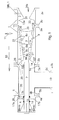
- Fig. 1 shows a longitudinal section through the Kavitatorrohr 1, which consists of several screwed against each other sections, namely the product inlet 2, the Kavitationskonus 3, the discharge chamber 5 and the Axial notebook entry 4, which follow each other in this order in the flow direction 10, the longitudinal direction of the Kavitatorrohrs 1 ,
- the individual pipe sections are conventionally screwed against one another by means of radially outwardly projecting flanges 2 a, b, 3 a, b, 4 a, 5 a, b, c.
- the discharge chamber 5 has a third flange, since there takes place the product outlet 19 of the medium, that is usually a mixture, radially to the side, as better in Fig. 2 seen.
- this discharge chamber 5 is still closed by the Axial notebook Entry 4, through which the axial rod 7 is guided to the outside, which forms the obstacle trees 9 in the interior 1a in the length range of Kavitationskonus 3 together with the obstacle bodies 8a, b located on it, and which can be adjusted and fixed in the longitudinal direction 10, which happens in the Axial die entry 4.
- the cavitation cone 3 is a substantially straight piece of pipe, but here again the free inner central passage from the beginning of the cavitation cone 3 over about 80% of its length a conical taper to a cross-sectional constriction 21 ', and in this axial constriction section are also in the central free space 1a, the obstacle bodies 8a-e of the obstacle tree 9th
- the interior 1a of the cavitation cone 3 performs a much faster cross-sectional widening 22 ', so that at the end of the cavitation cone 3 the free passage is only slightly smaller than at the beginning of the cavitation cone 3.
- the first two obstacle bodies 8a, b are preferably provided with not only one but two consecutively arranged tear-off edges 23, between which there is a circumferential, concave arc-shaped groove, so that the tear-off edges 23 are viewed in cross-section each form an acute angle.
- the further obstacle bodies 8c-8e are designed as radially outwardly projecting discs of different radius on the axial rod 7, so that between the individual fissure edges 23 of the individual obstacle bodies 8a-8e with respect to the conically narrowing inner wall of the cavitation cone 3 a substantially constant radial Distance as annular gap 18 remains.
- the obstacle bodies 8a-8e are each fixed axially fixed on the axial rod 7 and can only be moved together in the longitudinal direction 10 by means of the axial rod 7.
- another product inlet 3b may be present for a minor component to be admixed.
- This can be as indicated in the cross-sectional constriction of the product inlet 2 or in the formed as a concave baffle front end face of the first obstacle body 8a, in the latter case, then the supply is centrally through the hollow axial rod 7 from the rear end through a pipe.
- the relief chamber 5 is flanged to the cavitation cone 3, which also passes through in the axial direction 10 of the axial rod 7 is, from which the mixture, however, withdrawn in the radial direction through the radially attached outlet nozzle as the outlet opening 19 and is conveyed away.
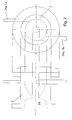
- the view shows the Fig. 2 of the cavitator in the flow direction that at several product inlets 24b1a and 24b1b in the cross-sectional taper of the product inlet 2 in this tangentially open and are offset from each other so that the réelle meetingsden components have the same direction of rotation.
- Fig. 2 also shows that can connect to the output port 19 of the radial product outlet 19 of the discharge chamber 5 alternatively again a segment in the form of the product inlet 2 ', in turn with the corresponding interior design contour and the described radial product inlets.
- the rear end of the discharge chamber 5 in the axial direction 10 is closed for the product flowing therethrough.
- the axial feedthrough 4 is arranged in the form of a straight piece of pipe with only a flange for flanging on the discharge chamber 5, which has a free diameter corresponding to the thickness of the axial rod 7, the tight, but axially movable, through the cylindrical passage 14 of the axial feedthrough. 4 through and out of the rear end is led out.
- this inner circumference of the axial passage 4 is axially spaced via a respective annular seal, in this case at the rear end of an O-ring seal and at the front, the discharge chamber 5 facing side, a lip seal 16, sealed.
- annular space 18 in the form of an annular recess formed in the passage 14 in the axial distance therebetween in the inner periphery of the passage 14 in which cleaning lines 17a, b supplied from the outside of the axial duct 4 open over the circumference, via which a cleaning agent, for example steam, can be supplied continuously or at certain time intervals for cleaning purposes.
- a cleaning agent for example steam
- a clamping cone 25 is used, which can be biased axially relative to the Axial notebook arrangement 4 by means of screwing. Since the clamping cone 25 also has an axial passage opening corresponding to the thickness of the axial rod 7, thereby the set axial position of the axial rod 7 is fixed by clamping the clamping cone 25 between the axial rod 7 and the axial feedthrough 4.
- Fig. 1 shows further that all inner corners 13a, b, ... are formed in the interior 1a of the Kavitatorrohrs 1 strongly rounded, to avoid the formation of calming zones of the medium to be passed there and thus the deposition and nucleation by longer-term whereabouts of medium in these inner corners. For the same reason, the transitions 12 between the individual obstacle bodies and the axial rod 7 are also formed strongly rounded.
- the corresponding flanges 2a, b, ..., 4a are not welded to the pipe sections, but integrally together with them at least in the individually manufactured for the cavitator sections product inlet 2, cavitation cone 3 and axial feedthrough 4 educated.
- the discharge chamber 5 is usually a purchased part, since it is a simple T-piece of a pipe connection.
- These mass produced Tees are usually made by welding the flanges on the pipe sections, however, in such a large-scale production, the non-porous aftertreatment of welds is possible, so that pore-free welded tees are commercially available. Otherwise, this element would have to be made from scratch.
Landscapes
- Chemical & Material Sciences (AREA)
- Dispersion Chemistry (AREA)
- Chemical Kinetics & Catalysis (AREA)
- Jet Pumps And Other Pumps (AREA)
- Saccharide Compounds (AREA)
- Steroid Compounds (AREA)
Applications Claiming Priority (2)
| Application Number | Priority Date | Filing Date | Title |
|---|---|---|---|
| DE202008008254 | 2008-06-19 | ||
| DE202008009204U DE202008009204U1 (de) | 2008-06-19 | 2008-07-09 | Kavitator |
Publications (2)
| Publication Number | Publication Date |
|---|---|
| EP2135667A1 true EP2135667A1 (fr) | 2009-12-23 |
| EP2135667B1 EP2135667B1 (fr) | 2010-12-08 |
Family
ID=39736811
Family Applications (1)
| Application Number | Title | Priority Date | Filing Date |
|---|---|---|---|
| EP09163116A Not-in-force EP2135667B1 (fr) | 2008-06-19 | 2009-06-18 | Cavitateur |
Country Status (3)
| Country | Link |
|---|---|
| EP (1) | EP2135667B1 (fr) |
| AT (1) | ATE490815T1 (fr) |
| DE (2) | DE202008009204U1 (fr) |
Cited By (4)
| Publication number | Priority date | Publication date | Assignee | Title |
|---|---|---|---|---|
| US9732068B1 (en) | 2013-03-15 | 2017-08-15 | GenSyn Technologies, Inc. | System for crystalizing chemical compounds and methodologies for utilizing the same |
| DE102018105138B3 (de) | 2018-03-06 | 2019-06-27 | Egm-Holding-International Gmbh | Kavitator |
| DE202022102005U1 (de) | 2022-04-13 | 2022-05-23 | Cvt Gmbh & Co. Kg | Vorrichtung zur Reinigung von Wasser und System zur Reinigung von Wasser |
| EP4573923A1 (fr) | 2023-12-18 | 2025-06-25 | Krones Ag | Dispositif et procédé de carbonatation de liquides |
Families Citing this family (4)
| Publication number | Priority date | Publication date | Assignee | Title |
|---|---|---|---|---|
| DE102013102593B4 (de) * | 2013-03-14 | 2019-05-23 | Cavitatorsystems Gmbh Mediale Mischsysteme & Anlagen | Verfahren zur Durchflussanpassung eines Cavitations-Mischers für ein hygienisch herzustellendes Fluid-Gemisch |
| EP3187257A1 (fr) * | 2015-12-29 | 2017-07-05 | AVARUS Suisse Holding AG | Dispositif de reacteur a cavitation destine a traiter des substances pouvant s'ecouler |
| RU197014U1 (ru) * | 2018-05-07 | 2020-03-24 | Федеральное государственное бюджетное образовательное учреждение высшего образования Нижегородская государственная сельскохозяйственная академия (ФГБОУ ВО Нижегородская ГСХА) | Вихревой кавитатор для предпосевной обработки семян |
| WO2020124263A1 (fr) * | 2018-12-21 | 2020-06-25 | Nanorial Technologies Ltd. | Appareils, procédés, et systèmes, pour mélanger, disperser des substances |
Citations (5)
| Publication number | Priority date | Publication date | Assignee | Title |
|---|---|---|---|---|
| FR1381821A (fr) * | 1964-02-04 | 1964-12-14 | Ultrasonics Ltd | Procédé et dispositif atomiseur pour la production d'aérosols ou autres mélangesintimes de liquides et de gaz |
| EP1359997A2 (fr) * | 2000-11-20 | 2003-11-12 | Five Star Technologies, Inc. | Appareil et procede de creation de cavitation hydrodynamique dans des fluides |
| US20060050608A1 (en) * | 2004-09-07 | 2006-03-09 | Kozyuk Oleg V | Device and method for creating hydrodynamic cavitation in fluids |
| EP1780176A1 (fr) * | 2005-10-25 | 2007-05-02 | Wagner, Manfred | Désinfection par cavitation |
| US20070205307A1 (en) * | 2006-03-03 | 2007-09-06 | Kozyuk Oleg V | Device and method for creating hydrodynamic cavitation in fluids |
-
2008
- 2008-07-09 DE DE202008009204U patent/DE202008009204U1/de not_active Expired - Lifetime
-
2009
- 2009-06-18 DE DE502009000223T patent/DE502009000223D1/de active Active
- 2009-06-18 EP EP09163116A patent/EP2135667B1/fr not_active Not-in-force
- 2009-06-18 AT AT09163116T patent/ATE490815T1/de active
Patent Citations (5)
| Publication number | Priority date | Publication date | Assignee | Title |
|---|---|---|---|---|
| FR1381821A (fr) * | 1964-02-04 | 1964-12-14 | Ultrasonics Ltd | Procédé et dispositif atomiseur pour la production d'aérosols ou autres mélangesintimes de liquides et de gaz |
| EP1359997A2 (fr) * | 2000-11-20 | 2003-11-12 | Five Star Technologies, Inc. | Appareil et procede de creation de cavitation hydrodynamique dans des fluides |
| US20060050608A1 (en) * | 2004-09-07 | 2006-03-09 | Kozyuk Oleg V | Device and method for creating hydrodynamic cavitation in fluids |
| EP1780176A1 (fr) * | 2005-10-25 | 2007-05-02 | Wagner, Manfred | Désinfection par cavitation |
| US20070205307A1 (en) * | 2006-03-03 | 2007-09-06 | Kozyuk Oleg V | Device and method for creating hydrodynamic cavitation in fluids |
Cited By (4)
| Publication number | Priority date | Publication date | Assignee | Title |
|---|---|---|---|---|
| US9732068B1 (en) | 2013-03-15 | 2017-08-15 | GenSyn Technologies, Inc. | System for crystalizing chemical compounds and methodologies for utilizing the same |
| DE102018105138B3 (de) | 2018-03-06 | 2019-06-27 | Egm-Holding-International Gmbh | Kavitator |
| DE202022102005U1 (de) | 2022-04-13 | 2022-05-23 | Cvt Gmbh & Co. Kg | Vorrichtung zur Reinigung von Wasser und System zur Reinigung von Wasser |
| EP4573923A1 (fr) | 2023-12-18 | 2025-06-25 | Krones Ag | Dispositif et procédé de carbonatation de liquides |
Also Published As
| Publication number | Publication date |
|---|---|
| DE202008009204U1 (de) | 2008-09-04 |
| DE502009000223D1 (de) | 2011-01-20 |
| EP2135667B1 (fr) | 2010-12-08 |
| ATE490815T1 (de) | 2010-12-15 |
Similar Documents
| Publication | Publication Date | Title |
|---|---|---|
| EP2135667B1 (fr) | Cavitateur | |
| EP1749564B1 (fr) | Stabilisateur pour mélanger ou bien stabiliser un mélange dans un champ de cavitation hydrodynamique | |
| DE102011007003B4 (de) | Bernoulli-Filter und Verfahren zum Filtrieren von Flüssigkeiten | |
| DE102010047782B3 (de) | Strömungsgleichrichter für geschlossene Rohrleitungen | |
| DE3717128C2 (fr) | ||
| EP1604162B1 (fr) | Echangeur thermique a faisceau tubulaire | |
| DE102014009015A1 (de) | Mischvorrichtung eines Abgasreinigungssystems einer Kraftfahrzeug-Brennkraftmaschine | |
| EP1924346B1 (fr) | Elément mélangeur pour l'inversion et le mélange de matières en écoulement dans un canal d'écoulement, et ensemble et mélangeur comprenant de tels éléments mélangeurs | |
| EP1109993A1 (fr) | Dispositif d'epuration pour gaz d'echappement | |
| DE102005059463B4 (de) | Vorrichtung zur Einflussnahme auf die Strömung im Bereich einer Rohrträgerplatte eines Rohrbündel-Wärmeaustauschers | |
| EP1780176B1 (fr) | Désinfection par cavitation | |
| EP1945337A1 (fr) | Chambre de turbulence | |
| DE102013010296A1 (de) | Verfahren und Injektor zum Einleiten eines dampfförmigen Wärmeträgers in ein flüssiges Produkt | |
| EP2382435B1 (fr) | Échangeur de chaleur à faisceau tubulaire avec un dispositif permettant d'influencer l'écoulement dans la région d'une plaque porte-tubes | |
| DE1776175B1 (de) | Demontierbarer waermetauscher | |
| WO2016062610A1 (fr) | Pompe à jet | |
| EP3338882A1 (fr) | Élément mélangeur à résistance et à action de mélange élevés | |
| EP1686865A2 (fr) | Module d'injection de vapeur servant a chauffer des produits aptes au pompage | |
| EP4089357B1 (fr) | Echangeur de chaleur | |
| DE102011082702A1 (de) | Düsenanordnung, Reinigungsvorrichtung und Verfahren zum Reinigen von innen liegenden Oberflächen von Hohlräumen | |
| DE102013102593B4 (de) | Verfahren zur Durchflussanpassung eines Cavitations-Mischers für ein hygienisch herzustellendes Fluid-Gemisch | |
| DE102024113004A1 (de) | Kopfvorrichtung zum Verändern einer Eigenschaft eines Fluides und Verfahren zum Herstellen einer Kopfvorrichtung | |
| WO2007020296A1 (fr) | Degazeur a cavitation | |
| EP4286037A2 (fr) | Dispositif de mélange compact pour mélanger des fluides | |
| DD270813A3 (de) | Einrichtung zur homogenen verteilung eines gas-/ fluessigkeitsgemisches |
Legal Events
| Date | Code | Title | Description |
|---|---|---|---|
| PUAI | Public reference made under article 153(3) epc to a published international application that has entered the european phase |
Free format text: ORIGINAL CODE: 0009012 |
|
| AK | Designated contracting states |
Kind code of ref document: A1 Designated state(s): AT BE BG CH CY CZ DE DK EE ES FI FR GB GR HR HU IE IS IT LI LT LU LV MC MK MT NL NO PL PT RO SE SI SK TR |
|
| 17P | Request for examination filed |
Effective date: 20091208 |
|
| 17Q | First examination report despatched |
Effective date: 20100108 |
|
| GRAP | Despatch of communication of intention to grant a patent |
Free format text: ORIGINAL CODE: EPIDOSNIGR1 |
|
| RIC1 | Information provided on ipc code assigned before grant |
Ipc: B01F 5/06 20060101AFI20100624BHEP |
|
| GRAS | Grant fee paid |
Free format text: ORIGINAL CODE: EPIDOSNIGR3 |
|
| GRAA | (expected) grant |
Free format text: ORIGINAL CODE: 0009210 |
|
| AK | Designated contracting states |
Kind code of ref document: B1 Designated state(s): AT BE BG CH CY CZ DE DK EE ES FI FR GB GR HR HU IE IS IT LI LT LU LV MC MK MT NL NO PL PT RO SE SI SK TR |
|
| REG | Reference to a national code |
Ref country code: GB Ref legal event code: FG4D Free format text: NOT ENGLISH |
|
| REG | Reference to a national code |
Ref country code: CH Ref legal event code: EP |
|
| REG | Reference to a national code |
Ref country code: IE Ref legal event code: FG4D |
|
| REF | Corresponds to: |
Ref document number: 502009000223 Country of ref document: DE Date of ref document: 20110120 Kind code of ref document: P |
|
| REG | Reference to a national code |
Ref country code: NL Ref legal event code: VDEP Effective date: 20101208 |
|
| PG25 | Lapsed in a contracting state [announced via postgrant information from national office to epo] |
Ref country code: LT Free format text: LAPSE BECAUSE OF FAILURE TO SUBMIT A TRANSLATION OF THE DESCRIPTION OR TO PAY THE FEE WITHIN THE PRESCRIBED TIME-LIMIT Effective date: 20101208 Ref country code: NO Free format text: LAPSE BECAUSE OF FAILURE TO SUBMIT A TRANSLATION OF THE DESCRIPTION OR TO PAY THE FEE WITHIN THE PRESCRIBED TIME-LIMIT Effective date: 20110308 |
|
| LTIE | Lt: invalidation of european patent or patent extension |
Effective date: 20101208 |
|
| PG25 | Lapsed in a contracting state [announced via postgrant information from national office to epo] |
Ref country code: LV Free format text: LAPSE BECAUSE OF FAILURE TO SUBMIT A TRANSLATION OF THE DESCRIPTION OR TO PAY THE FEE WITHIN THE PRESCRIBED TIME-LIMIT Effective date: 20101208 Ref country code: CY Free format text: LAPSE BECAUSE OF FAILURE TO SUBMIT A TRANSLATION OF THE DESCRIPTION OR TO PAY THE FEE WITHIN THE PRESCRIBED TIME-LIMIT Effective date: 20101208 Ref country code: HR Free format text: LAPSE BECAUSE OF FAILURE TO SUBMIT A TRANSLATION OF THE DESCRIPTION OR TO PAY THE FEE WITHIN THE PRESCRIBED TIME-LIMIT Effective date: 20101208 Ref country code: FI Free format text: LAPSE BECAUSE OF FAILURE TO SUBMIT A TRANSLATION OF THE DESCRIPTION OR TO PAY THE FEE WITHIN THE PRESCRIBED TIME-LIMIT Effective date: 20101208 Ref country code: SI Free format text: LAPSE BECAUSE OF FAILURE TO SUBMIT A TRANSLATION OF THE DESCRIPTION OR TO PAY THE FEE WITHIN THE PRESCRIBED TIME-LIMIT Effective date: 20101208 Ref country code: SE Free format text: LAPSE BECAUSE OF FAILURE TO SUBMIT A TRANSLATION OF THE DESCRIPTION OR TO PAY THE FEE WITHIN THE PRESCRIBED TIME-LIMIT Effective date: 20101208 Ref country code: BG Free format text: LAPSE BECAUSE OF FAILURE TO SUBMIT A TRANSLATION OF THE DESCRIPTION OR TO PAY THE FEE WITHIN THE PRESCRIBED TIME-LIMIT Effective date: 20110308 Ref country code: NL Free format text: LAPSE BECAUSE OF FAILURE TO SUBMIT A TRANSLATION OF THE DESCRIPTION OR TO PAY THE FEE WITHIN THE PRESCRIBED TIME-LIMIT Effective date: 20101208 |
|
| REG | Reference to a national code |
Ref country code: IE Ref legal event code: FD4D |
|
| PG25 | Lapsed in a contracting state [announced via postgrant information from national office to epo] |
Ref country code: EE Free format text: LAPSE BECAUSE OF FAILURE TO SUBMIT A TRANSLATION OF THE DESCRIPTION OR TO PAY THE FEE WITHIN THE PRESCRIBED TIME-LIMIT Effective date: 20101208 Ref country code: IS Free format text: LAPSE BECAUSE OF FAILURE TO SUBMIT A TRANSLATION OF THE DESCRIPTION OR TO PAY THE FEE WITHIN THE PRESCRIBED TIME-LIMIT Effective date: 20110408 Ref country code: GR Free format text: LAPSE BECAUSE OF FAILURE TO SUBMIT A TRANSLATION OF THE DESCRIPTION OR TO PAY THE FEE WITHIN THE PRESCRIBED TIME-LIMIT Effective date: 20110309 Ref country code: CZ Free format text: LAPSE BECAUSE OF FAILURE TO SUBMIT A TRANSLATION OF THE DESCRIPTION OR TO PAY THE FEE WITHIN THE PRESCRIBED TIME-LIMIT Effective date: 20101208 Ref country code: PT Free format text: LAPSE BECAUSE OF FAILURE TO SUBMIT A TRANSLATION OF THE DESCRIPTION OR TO PAY THE FEE WITHIN THE PRESCRIBED TIME-LIMIT Effective date: 20110408 Ref country code: ES Free format text: LAPSE BECAUSE OF FAILURE TO SUBMIT A TRANSLATION OF THE DESCRIPTION OR TO PAY THE FEE WITHIN THE PRESCRIBED TIME-LIMIT Effective date: 20110319 Ref country code: IE Free format text: LAPSE BECAUSE OF FAILURE TO SUBMIT A TRANSLATION OF THE DESCRIPTION OR TO PAY THE FEE WITHIN THE PRESCRIBED TIME-LIMIT Effective date: 20101208 |
|
| PG25 | Lapsed in a contracting state [announced via postgrant information from national office to epo] |
Ref country code: SK Free format text: LAPSE BECAUSE OF FAILURE TO SUBMIT A TRANSLATION OF THE DESCRIPTION OR TO PAY THE FEE WITHIN THE PRESCRIBED TIME-LIMIT Effective date: 20101208 Ref country code: PL Free format text: LAPSE BECAUSE OF FAILURE TO SUBMIT A TRANSLATION OF THE DESCRIPTION OR TO PAY THE FEE WITHIN THE PRESCRIBED TIME-LIMIT Effective date: 20101208 Ref country code: RO Free format text: LAPSE BECAUSE OF FAILURE TO SUBMIT A TRANSLATION OF THE DESCRIPTION OR TO PAY THE FEE WITHIN THE PRESCRIBED TIME-LIMIT Effective date: 20101208 |
|
| PLBE | No opposition filed within time limit |
Free format text: ORIGINAL CODE: 0009261 |
|
| STAA | Information on the status of an ep patent application or granted ep patent |
Free format text: STATUS: NO OPPOSITION FILED WITHIN TIME LIMIT |
|
| PG25 | Lapsed in a contracting state [announced via postgrant information from national office to epo] |
Ref country code: DK Free format text: LAPSE BECAUSE OF FAILURE TO SUBMIT A TRANSLATION OF THE DESCRIPTION OR TO PAY THE FEE WITHIN THE PRESCRIBED TIME-LIMIT Effective date: 20101208 |
|
| 26N | No opposition filed |
Effective date: 20110909 |
|
| PG25 | Lapsed in a contracting state [announced via postgrant information from national office to epo] |
Ref country code: IT Free format text: LAPSE BECAUSE OF FAILURE TO SUBMIT A TRANSLATION OF THE DESCRIPTION OR TO PAY THE FEE WITHIN THE PRESCRIBED TIME-LIMIT Effective date: 20101208 Ref country code: MT Free format text: LAPSE BECAUSE OF FAILURE TO SUBMIT A TRANSLATION OF THE DESCRIPTION OR TO PAY THE FEE WITHIN THE PRESCRIBED TIME-LIMIT Effective date: 20101208 |
|
| BERE | Be: lapsed |
Owner name: CAVITATOR SYSTEMS G.M.B.H. Effective date: 20110630 |
|
| REG | Reference to a national code |
Ref country code: DE Ref legal event code: R097 Ref document number: 502009000223 Country of ref document: DE Effective date: 20110909 |
|
| PG25 | Lapsed in a contracting state [announced via postgrant information from national office to epo] |
Ref country code: BE Free format text: LAPSE BECAUSE OF NON-PAYMENT OF DUE FEES Effective date: 20110630 |
|
| PG25 | Lapsed in a contracting state [announced via postgrant information from national office to epo] |
Ref country code: MK Free format text: LAPSE BECAUSE OF FAILURE TO SUBMIT A TRANSLATION OF THE DESCRIPTION OR TO PAY THE FEE WITHIN THE PRESCRIBED TIME-LIMIT Effective date: 20101208 |
|
| PG25 | Lapsed in a contracting state [announced via postgrant information from national office to epo] |
Ref country code: MC Free format text: LAPSE BECAUSE OF NON-PAYMENT OF DUE FEES Effective date: 20110630 |
|
| PG25 | Lapsed in a contracting state [announced via postgrant information from national office to epo] |
Ref country code: LU Free format text: LAPSE BECAUSE OF NON-PAYMENT OF DUE FEES Effective date: 20110618 |
|
| PG25 | Lapsed in a contracting state [announced via postgrant information from national office to epo] |
Ref country code: TR Free format text: LAPSE BECAUSE OF FAILURE TO SUBMIT A TRANSLATION OF THE DESCRIPTION OR TO PAY THE FEE WITHIN THE PRESCRIBED TIME-LIMIT Effective date: 20101208 |
|
| PG25 | Lapsed in a contracting state [announced via postgrant information from national office to epo] |
Ref country code: HU Free format text: LAPSE BECAUSE OF FAILURE TO SUBMIT A TRANSLATION OF THE DESCRIPTION OR TO PAY THE FEE WITHIN THE PRESCRIBED TIME-LIMIT Effective date: 20101208 |
|
| REG | Reference to a national code |
Ref country code: CH Ref legal event code: PL |
|
| PG25 | Lapsed in a contracting state [announced via postgrant information from national office to epo] |
Ref country code: CH Free format text: LAPSE BECAUSE OF NON-PAYMENT OF DUE FEES Effective date: 20130630 Ref country code: LI Free format text: LAPSE BECAUSE OF NON-PAYMENT OF DUE FEES Effective date: 20130630 |
|
| REG | Reference to a national code |
Ref country code: DE Ref legal event code: R082 Ref document number: 502009000223 Country of ref document: DE Representative=s name: PATENTANWAELTE WEICKMANN & WEICKMANN, DE Ref country code: DE Ref legal event code: R082 Ref document number: 502009000223 Country of ref document: DE Representative=s name: WEICKMANN & WEICKMANN PATENTANWAELTE - RECHTSA, DE Ref country code: DE Ref legal event code: R082 Ref document number: 502009000223 Country of ref document: DE Representative=s name: WEICKMANN & WEICKMANN PATENT- UND RECHTSANWAEL, DE |
|
| REG | Reference to a national code |
Ref country code: FR Ref legal event code: PLFP Year of fee payment: 8 |
|
| REG | Reference to a national code |
Ref country code: DE Ref legal event code: R082 Ref document number: 502009000223 Country of ref document: DE Representative=s name: WEICKMANN & WEICKMANN PATENTANWAELTE - RECHTSA, DE Ref country code: DE Ref legal event code: R081 Ref document number: 502009000223 Country of ref document: DE Owner name: CAVITATORSYSTEMS GMBH MEDIALE MISCHSYSTEME & A, DE Free format text: FORMER OWNER: CAVITATOR SYSTEMS GMBH, 84036 LANDSHUT, DE Ref country code: DE Ref legal event code: R082 Ref document number: 502009000223 Country of ref document: DE Representative=s name: WEICKMANN & WEICKMANN PATENT- UND RECHTSANWAEL, DE |
|
| REG | Reference to a national code |
Ref country code: FR Ref legal event code: PLFP Year of fee payment: 9 |
|
| REG | Reference to a national code |
Ref country code: FR Ref legal event code: PLFP Year of fee payment: 10 |
|
| PGFP | Annual fee paid to national office [announced via postgrant information from national office to epo] |
Ref country code: FR Payment date: 20200623 Year of fee payment: 12 |
|
| PGFP | Annual fee paid to national office [announced via postgrant information from national office to epo] |
Ref country code: GB Payment date: 20200625 Year of fee payment: 12 |
|
| PGFP | Annual fee paid to national office [announced via postgrant information from national office to epo] |
Ref country code: AT Payment date: 20200618 Year of fee payment: 12 |
|
| PGFP | Annual fee paid to national office [announced via postgrant information from national office to epo] |
Ref country code: DE Payment date: 20200819 Year of fee payment: 12 |
|
| REG | Reference to a national code |
Ref country code: DE Ref legal event code: R079 Ref document number: 502009000223 Country of ref document: DE Free format text: PREVIOUS MAIN CLASS: B01F0005060000 Ipc: B01F0025400000 |
|
| REG | Reference to a national code |
Ref country code: DE Ref legal event code: R119 Ref document number: 502009000223 Country of ref document: DE |
|
| REG | Reference to a national code |
Ref country code: AT Ref legal event code: MM01 Ref document number: 490815 Country of ref document: AT Kind code of ref document: T Effective date: 20210618 |
|
| GBPC | Gb: european patent ceased through non-payment of renewal fee |
Effective date: 20210618 |
|
| PG25 | Lapsed in a contracting state [announced via postgrant information from national office to epo] |
Ref country code: GB Free format text: LAPSE BECAUSE OF NON-PAYMENT OF DUE FEES Effective date: 20210618 Ref country code: DE Free format text: LAPSE BECAUSE OF NON-PAYMENT OF DUE FEES Effective date: 20220101 Ref country code: AT Free format text: LAPSE BECAUSE OF NON-PAYMENT OF DUE FEES Effective date: 20210618 |
|
| PG25 | Lapsed in a contracting state [announced via postgrant information from national office to epo] |
Ref country code: FR Free format text: LAPSE BECAUSE OF NON-PAYMENT OF DUE FEES Effective date: 20210630 |