EP2135687A1 - Reinigungsvorrichtung und Reinigungsverfahren - Google Patents
Reinigungsvorrichtung und Reinigungsverfahren Download PDFInfo
- Publication number
- EP2135687A1 EP2135687A1 EP09162888A EP09162888A EP2135687A1 EP 2135687 A1 EP2135687 A1 EP 2135687A1 EP 09162888 A EP09162888 A EP 09162888A EP 09162888 A EP09162888 A EP 09162888A EP 2135687 A1 EP2135687 A1 EP 2135687A1
- Authority
- EP
- European Patent Office
- Prior art keywords
- cleaning
- cleaned
- cleaning tank
- cleaning medium
- tank
- Prior art date
- Legal status (The legal status is an assumption and is not a legal conclusion. Google has not performed a legal analysis and makes no representation as to the accuracy of the status listed.)
- Granted
Links
- 238000004140 cleaning Methods 0.000 title claims abstract description 375
- 238000000034 method Methods 0.000 title claims description 20
- 238000010586 diagram Methods 0.000 description 8
- 239000000428 dust Substances 0.000 description 8
- 239000000843 powder Substances 0.000 description 6
- 239000000463 material Substances 0.000 description 5
- 230000000694 effects Effects 0.000 description 4
- 239000000126 substance Substances 0.000 description 3
- XLYOFNOQVPJJNP-UHFFFAOYSA-N water Substances O XLYOFNOQVPJJNP-UHFFFAOYSA-N 0.000 description 3
- 230000003247 decreasing effect Effects 0.000 description 2
- 239000004744 fabric Substances 0.000 description 2
- 230000002093 peripheral effect Effects 0.000 description 2
- 238000004064 recycling Methods 0.000 description 2
- 239000011347 resin Substances 0.000 description 2
- 229920005989 resin Polymers 0.000 description 2
- 239000007787 solid Substances 0.000 description 2
- 239000002699 waste material Substances 0.000 description 2
- 238000007664 blowing Methods 0.000 description 1
- 239000000919 ceramic Substances 0.000 description 1
- 238000001035 drying Methods 0.000 description 1
- 230000007613 environmental effect Effects 0.000 description 1
- 230000005484 gravity Effects 0.000 description 1
- 238000011086 high cleaning Methods 0.000 description 1
- 238000002347 injection Methods 0.000 description 1
- 239000007924 injection Substances 0.000 description 1
- 239000002184 metal Substances 0.000 description 1
- 239000000123 paper Substances 0.000 description 1
- 239000002245 particle Substances 0.000 description 1
- 239000004033 plastic Substances 0.000 description 1
- 238000007789 sealing Methods 0.000 description 1
- 230000035939 shock Effects 0.000 description 1
- 239000000243 solution Substances 0.000 description 1
- 230000000087 stabilizing effect Effects 0.000 description 1
- 210000000707 wrist Anatomy 0.000 description 1
Images


Classifications
-
- G—PHYSICS
- G03—PHOTOGRAPHY; CINEMATOGRAPHY; ANALOGOUS TECHNIQUES USING WAVES OTHER THAN OPTICAL WAVES; ELECTROGRAPHY; HOLOGRAPHY
- G03G—ELECTROGRAPHY; ELECTROPHOTOGRAPHY; MAGNETOGRAPHY
- G03G15/00—Apparatus for electrographic processes using a charge pattern
- G03G15/06—Apparatus for electrographic processes using a charge pattern for developing
- G03G15/08—Apparatus for electrographic processes using a charge pattern for developing using a solid developer, e.g. powder developer
- G03G15/0894—Reconditioning of the developer unit, i.e. reusing or recycling parts of the unit, e.g. resealing of the unit before refilling with toner
-
- B—PERFORMING OPERATIONS; TRANSPORTING
- B08—CLEANING
- B08B—CLEANING IN GENERAL; PREVENTION OF FOULING IN GENERAL
- B08B15/00—Preventing escape of dirt or fumes from the area where they are produced; Collecting or removing dirt or fumes from that area
- B08B15/02—Preventing escape of dirt or fumes from the area where they are produced; Collecting or removing dirt or fumes from that area using chambers or hoods covering the area
-
- B—PERFORMING OPERATIONS; TRANSPORTING
- B08—CLEANING
- B08B—CLEANING IN GENERAL; PREVENTION OF FOULING IN GENERAL
- B08B15/00—Preventing escape of dirt or fumes from the area where they are produced; Collecting or removing dirt or fumes from that area
- B08B15/04—Preventing escape of dirt or fumes from the area where they are produced; Collecting or removing dirt or fumes from that area from a small area, e.g. a tool
-
- B—PERFORMING OPERATIONS; TRANSPORTING
- B08—CLEANING
- B08B—CLEANING IN GENERAL; PREVENTION OF FOULING IN GENERAL
- B08B7/00—Cleaning by methods not provided for in a single other subclass or a single group in this subclass
- B08B7/02—Cleaning by methods not provided for in a single other subclass or a single group in this subclass by distortion, beating, or vibration of the surface to be cleaned
-
- B—PERFORMING OPERATIONS; TRANSPORTING
- B24—GRINDING; POLISHING
- B24C—ABRASIVE OR RELATED BLASTING WITH PARTICULATE MATERIAL
- B24C9/00—Appurtenances of abrasive blasting machines or devices, e.g. working chambers, arrangements for handling used abrasive material
Definitions
- the present invention generally relates to a cleaning apparatus and a cleaning method which is used in an electrophotographic type image forming apparatus such as a copier or a laser printer to remove deposits such as dust or an extraneous substance attached or fixed on a component having a complicated shape by using a solid cleaning medium. More specifically, the present invention provides an effective technique to efficiently clean a long and thin object to be cleaned.
- a wet-type cleaning method For the cleaning, in general, a wet-type cleaning method has been often employed, such as an ultrasonic wave cleaning method to dip the components or units in a water tank and apply ultrasonic waves, and a shower cleaning method to direct a high speed stream of water to an object to be cleaned by using a nozzle.
- an ultrasonic wave cleaning method to dip the components or units in a water tank and apply ultrasonic waves
- a shower cleaning method to direct a high speed stream of water to an object to be cleaned by using a nozzle.
- a cleaning apparatus disclosed in Patent Document 1 flows air in a cleaning tank, causing lightweight, solid, and easy-to-fly cleaning media to fly in the cleaning tank, so that the cleaning media continuously contact an object to be cleaned, and a deposit attached on the object to be cleaned (attached dust, powder, or a stain fixed in a film state on the object to be cleaned) is separated without using water.
- a cleaning performance equivalent to or more than the ultrasonic wave cleaning method can be exhibited even with a small amount of the cleaning media.
- a method to clean a whole surface of the object to be cleaned without using a cleaning tank for storing the object to be cleaned without using a cleaning tank for storing the object to be cleaned.
- the whole surface of the object to be cleaned is cleaned by removing an extraneous substance in a small spot area of the object by using a blast gun and the like and scanning a blowing position of the blast gun over the object to be cleaned.
- a cleaning apparatus disclosed in Patent Document 2 causes flying substances formed of a sponge or a rubber sphere having a hollow center, which have a diameter of about 10 to 30 mm, to fly in a cone shaped housing by using compressed air, so as to collide with and clean a spot area of the object to be cleaned.
- the dry-type cleaning apparatus as disclosed in Patent Document 1 employs a method to put the object to be cleaned in the cleaning tank so as to be collided with cleaning media. Therefore, a cleaning tank that has a volume equal to or more than the size of the object to be cleaned has been required to be prepared. Because of this, it has been difficult to clean a large object to be cleaned. Moreover, when various components in different sizes are to be cleaned by one cleaning apparatus, a cleaning tank and process conditions have had to be adjusted for the largest component. In this case, when a small object to be cleaned is put in the cleaning tank, it is inefficient since flying cleaning media which do not contribute to cleaning are increased. Further, since an optimum cleaning condition changes depending on the size of the object to be cleaned, there have been problems in that it has been troublesome to adjust the condition in cleaning various kinds of objects, and quality of the cleaning is not consistent.
- the inside of the housing has a positive pressure. Therefore, it has been difficult to prevent leakage of the small and flexible flying media. Moreover, this cleaning method is more suitable for cleaning a plane surface. In the case of cleaning an object having a three-dimensionally complicated shape, there is usually a space formed between the housing and the object to be cleaned. Thus, it has been difficult to perform cleaning without leaking the cleaning medium. When the cleaning medium is leaked, there have been problems in that an operation environment is polluted, and at the same time, the number of cleaning media flying in the housing is decreased and that the cleaning performance is degraded.
- the present invention is made to improve such disadvantages and provides a cleaning apparatus and a cleaning method which can efficiently clean even an object to be cleaned having a complicated surface shape, by causing cleaning media to fly in a cleaning tank without stagnation as well as by downsizing the volume of the cleaning tank.
- the present invention is made to obtain a consistent cleaning performance by effectively using cleaning media by quickly collecting the cleaning media into the cleaning tank when the cleaning media leak from the space in the cleaning tank where the cleaning medium fly.
- a cleaning apparatus for cleaning an object to be cleaned by allowing a cleaning medium caused to fly by an air flow to collide with the object to be cleaned includes a cleaning tank in which the cleaning medium is caused to fly by the air flow and which has an opening configured to allow the object to be cleaned to pass through; a cleaning medium accelerating part provided at a bottom part of the cleaning tank and configured to inject the air flow to cause the cleaning medium to fly; a hollow elongated member configured to have substantially the same inner diameter as a diameter of the opening of the cleaning tank, connected outside the opening of the cleaning tank, and configured to form a movement path for the object to be cleaned; and a cleaning medium returning part configured to return the cleaning medium stagnant in the hollow elongated member into the cleaning tank.
- a method for cleaning an object to be cleaned by colliding a cleaning medium caused to fly by an air flow with the object to be cleaned in a cleaning tank having an opening through which the object to be cleaned can pass through includes the steps of sucking air in the cleaning tank; inserting the object to be cleaned into the cleaning tank through a cylindrical movement path for the object to be cleaned, said cylindrical movement path having the substantially same inner diameter as a diameter of the opening and being connected outside the opening; and injecting an air flow into the cleaning tank in which the object to be cleaned is inserted so as to cause the cleaning medium to fly.
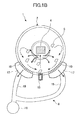
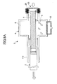
- FIGS. 1A and 1B show configurations of a cleaning apparatus 1 of the present invention.
- FIGS. 1A and 1B show a front cross-sectional view and a side cross-sectional view of the cleaning apparatus 1, respectively.
- the cleaning apparatus 1 includes a cleaning tank unit 2, a holding part 3, a cleaning medium accelerating part 7, and a suction part 8.
- a deposit dust, powder, or a stain fixed in a film state
- colliding cleaning media 5 caused to fly by an air flow supplied by the cleaning medium accelerating part 7 with the object to be cleaned.
- the removed deposit is exhausted outside the cleaning tank unit 2 by the suction part 8.
- the cleaning medium 5 used in the cleaning apparatus 1 is formed of a thin piece material in a square shape having a side of 5 to 10 mm and a thickness of 0.1 to 0.2 mm, by using any flexible material having resistance against shock, such as ceramic, cloth, paper, and resin. In some cases, it is effective to change the size or material of the cleaning medium 5 depending on the object 4 to be cleaned. Appropriate conditions for the cleaning medium 5 can be selected in accordance with the object 4 to be cleaned, without being limited to the above-described conditions.
- the cleaning medium 5 when a force of an air flow is applied to the cleaning medium 5 having a thin piece shape in a direction where a projection area is larger, the cleaning medium 5 is easily accelerated and caused to fly because the cleaning medium 5 having a thin piece shape has quite a small mass with respect to air resistance. Moreover, the cleaning medium 5 has low air resistance in a direction where the projection area is small. When the cleaning medium 5 flies in that direction, a high speed movement is maintained for a long distance. Therefore, the cleaning medium 5 has a high energy and a large effect when contacted with the object 4 to be cleaned. Thus, the deposit (dust, powder, or a stain fixed in a film state) attached on the object 4 to be cleaned can be effectively removed. By repeating circulation of the cleaning medium 5, the cleaning medium 5 contacts the object 4 to be cleaned more frequently. Therefore, a cleaning efficiency of the cleaning apparatus 1 can be enhanced.
- air resistance of the cleaning medium 5 having a thin piece shape largely changes depending on its posture. Therefore, the cleaning medium 5 repeatedly contacts the object 4 to be cleaned by moving in a complicated way such as rapidly changing directions as well as moving along the air flow. Therefore, a high cleaning performance can be exhibited for the object 4 to be cleaned, having a relatively complicated shape.
- the cleaning tank unit 2 includes a cleaning tank 6, separating parts 10, and hollow elongated members 11a and 11b.
- the cleaning tank 6 includes the cleaning medium accelerating part 7, and the separating parts 10.
- the cleaning tank 6 is formed so that a cleaning medium flying space 9 in the cleaning tank 6 has, for example, a cylindrical shape. Opposing end parts of the cleaning medium flying space 9 are sealed with opposing side walls, and circular openings each having such a diameter that allows the object 4 to be cleaned to pass through are provided at centers of the opposing side walls.
- the separating parts 10 are formed of a porous member such as a wire mesh, a plastic mesh, a mesh, a perforated metal, or a slit plate, having small apertures or slits which allow gas or a deposit (dust, powder, or a stain fixed in a film state) to pass through but does not allow the cleaning medium 5 to pass through.
- the separating parts 10 are formed of the above-described member in a smooth shape such as a semi-cylindrical shape, which does not stagnate the cleaning medium 5, at parts of a wall of the cylindrical shape of the cleaning tank 6 with a predetermined distance provided from the bottommost part of the cleaning tank 6.
- the hollow elongated members 11a and 11b have the same inner diameters as the openings provided at the centers of the opposing side walls of the cleaning tank 6.
- the hollow elongated members 11a and 11b are formed of cylinders having predetermined lengths and connected outside the respective openings of the opposing side walls of the cleaning tank 6 to form a movement path of the object 4 to be cleaned.
- an opening end of the hollow elongated member 11b, which is at the opposite side to the cleaning tank 6, is covered with a porous member 12 having a mesh or slits that allows an air flow to pass through but does not allow the cleaning medium 5 to pass through.
- the cleaning medium accelerating part 7 includes a cleaning medium accelerating nozzle 13 having plural injecting holes, a compressed air supplying apparatus 14 formed of a compressor, a control valve 15, and an airline 16.
- the cleaning medium accelerating nozzle 13 has the plural injecting holes aligned in a straight line at a bottom surface of the cleaning tank 6, passing through the cleaning tank 6.
- the compressed air supplying apparatus 14 supplies compressed air through the airline 16 having the control valve 15 to the cleaning medium accelerating nozzle 13 to cause the nozzle 13 to inject an air so that the cleaning media 5 fly.
- the control valve 15 controls the compressed air supplied by the compressed air supplying apparatus 14.
- the airline 16 supplies the compressed air supplied from the compressed air supplying apparatus 14 to the cleaning medium accelerating nozzle 13.
- the suction part 8 includes suction ducts 17, a suction pipe 19, and a suction apparatus 18.
- the suction ducts 17 remove dust or a deposit (dust, powder, or a stain fixed in a film state) included in the air in the cleaning tank 6 or attached on the cleaning medium 5 by the separating parts 10 and sucks them.
- the suction apparatus 18 sucks the air and/or the deposit in the cleaning tank 6 through the suction pipe 19.
- the suction pipe 19 carries the air and/or deposit, and the like sucked by the suction ducts 17 through the separating parts 10.
- the holding part 3 includes a cylindrical linear acting arm 20 having an inner diameter slightly smaller (for example, an outer diameter smaller by about several millimeters) than the openings of the hollow elongated members 11a and 11b, and a grip part 21 provided rotatably at a leading end of the linear acting arm 20.
- the grip part 21 is provided with a scraper part 22 formed of a mesh, slits, or a dense brush that allows an air flow pass through to a peripheral surface but does not allow the cleaning medium 5 to pass through, so as to internally contact inner surfaces of the hollow elongated member 11a.
- the cleaning apparatus 1 drives the suction apparatus 18 at all times to suck air in the cleaning tank 6 from the suction ducts 17 through the separating parts 10.
- the opening of the hollow elongated member 11a and the porous member 12 of the hollow elongated member 11b generate a suction air flow directed into the cleaning tank 6.
- an operator grips the object 4 to be cleaned by the grip part 21 of the holding part 3, and inserts the holding part 3 by which the object 4 to be cleaned is held, through the opening of the hollow elongated member 11a, to insert the object 4 to be cleaned into the cleaning tank 6.
- the compressed air supplying apparatus 14 which constitutes the cleaning medium accelerating part 7 is driven.
- the control valve 15 While driving the compressed air supplying apparatus 14, the control valve 15 is opened to supply the compressed air to the cleaning medium accelerating nozzle 13, and an air flow is generated perpendicularly upward in the cleaning medium flying space 9 from the cleaning medium accelerating nozzle 13. By this air flow, the cleaning media 5 fly and a part of them collide with the object 4 to be cleaned, thereby a deposit attached on the surface of the object 4 to be cleaned is efficiently removed.
- a part of the cleaning media 5 which have collided with the object 4 to be cleaned fly in a direction of the movement path of the hollow elongated members 11a and 11b while the others fly radially to ultimately reach an inner wall of the cleaning tank 6. Further, the cleaning media 5 which have not collided with the object 4 to be cleaned fly straight as they are and collide with a ceiling of the cleaning tank 6.
- the compressed air supplied by the cleaning medium accelerating part 7 flows along an inner wall of the cylinder perpendicularly crossing the opposing side walls of the cleaning tank 6, and at the same time, a circulation air flow is generated by an air flow sucked by the suction apparatus 18 to flow to the bottom surface of the cleaning tank 6.
- a part of the cleaning media 5 which have leaked into the hollow elongated members 11a and 11b is reduced in speed or sucked by an air flow generated in the hollow elongated members 11a and 11b by the suction of the suction apparatus 18 to be collected into the cleaning tank 6. Further, another part of the cleaning media 5 which have leaked into the hollow elongated member 11a is prevented by the scraper part 22 of the holding part 3 to be collected into the cleaning tank 6. In this manner, the cleaning media 5 can be effectively used and a cleaning efficiency can be improved. Moreover, it can be prevented that the cleaning media 5 are leaked outside from the movement path of the object 4 to be cleaned, which is formed of the hollow elongated member 11a.
- the cleaning media 5 slide down to the vicinity of the cleaning media accelerating nozzle 13 by being sucked over the separating part 10, a deposit is separated and sucked from the cleaning media 5 when passing through the separating part 10.
- the deposit separated by the separating part 10 is collected by the suction apparatus 19 through the suction duct 17 and the suction pipe 19.
- the cleaning media 5 which have reached the vicinity of the cleaning media accelerating nozzle 13 is caused to fly again in a perpendicular upward direction by an air flow injected by the cleaning media accelerating nozzle 13. By repeating this operation, a deposit attached on the surface of the object 4 to be cleaned is removed.
- the linear acting arm 20 of the holding part 3 While cleaning the object 4 to be cleaned by using the flying cleaning media 5, the linear acting arm 20 of the holding part 3 is rotated to rotate the object 4 to be cleaned, and at the same time the linear acting arm 20 is moved back and forth so as to clean a whole surface of the object 4 to be cleaned.
- the whole surface of the object 4 to be cleaned having a long size can be surely cleaned.
- the cleaning medium 5 When the cleaning medium 5 is caused to fly by the cleaning medium accelerating nozzle 13 to clean the object 4 to be cleaned, it is more effective to repeat injecting and stopping of an air flow from the cleaning medium accelerating nozzle 13 by intermittently driving the control valve 15. By repeating injecting and stopping of the air flow in this manner, the cleaning media 5 which have entered the hollow elongated members 11a and 11b can be surely collected into the cleaning tank 6 by a suction air flow generated in the hollow elongated members 11a and 11b by suction of the suction apparatus 18. Further, by rotating the object 4 to be cleaned at a high speed by using a posture changing function of the holding part 3 when the cleaning medium accelerating nozzle 13 is not injecting an air flow, a centrifugal force is applied to the cleaning media 5. Therefore, the cleaning media 5 can be more reliably separated from the object 4 to be cleaned.
- a cleaning performance can be enhanced.
- the object 4 to be cleaned straight so as to be taken in and out the cleaning tank 6 the object 4 to be cleaned with a size equal to or larger than the cleaning tank 6 can be cleaned even when the cleaning tank 6 has a small volume.
- the cleaning tank 6 by configuring the cleaning tank 6 to have a smaller volume, a flying density of the cleaning media 5 can be increased. As a result, a cleaning performance can be considerably improved compared to a conventional cleaning tank.
- the cleaning tank 6 is formed in a cylindrical shape.
- the shape of the cleaning tank 6 is not limited to the cylindrical shape as long as the cleaning media 5 circulate along opposing side walls and an inner wall perpendicularly crossing the side walls of the cleaning tank 6 and moves to the position of the cleaning medium accelerating nozzle 13 without stagnation.
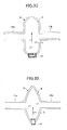
- the cleaning tank 6 may have a front cross-section in a prism shape as shown in FIG. 3A or a ⁇ -shape which is along a convection flow as shown in FIG. 3B , or a side cross-section in a U-shape as shown in FIG. 3C or a V-shape as shown in FIG. 3D .
- the holding part 3 may have any configuration as long as it can hold the object 4 to be cleaned and change the posture of the held object 4 to be cleaned. As shown in FIG. 4 , the object 4 to be cleaned may be directly held by an operator. When the operator holds the object 4 to be cleaned in this manner, a leakage of the cleaning media 5 can be more effectively prevented when the scraper part 22 is mounted on a wrist of the operator.
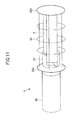
- a cleaning medium accelerating nozzle 13a having two systems of injecting holes 23a and 23b inclined at predetermined angles with respect to the perpendicular upward direction is provided at a bottom part of the cleaning tank 6. Pressurized air to be supplied to the two systems of the injecting holes 23a and 23b is switched by a switching valve 24 so as to generate an air flow along a cylindrical inner wall of the cleaning tank 6.
- the cleaning medium accelerating nozzle 13 may be provided for each path of air flows so that the cleaning medium 5 is caused to fly along the cylindrical inner wall of the cleaning tank 6 by an air flow alternately generated along the cylindrical inner wall of the cleaning tank 6 from the cleaning medium accelerating nozzle 13a. Then, the flying cleaning medium 5 may be collided with the object 4 to be cleaned by the air flow alternately injected from the cleaning medium accelerating nozzle 13.
- the two systems of the injecting holes 23a and 23b are provided for the cleaning medium accelerating nozzle 13a, however, one injecting hole 23 may be provided for the cleaning medium accelerating nozzle 13a and an angle of the cleaning medium accelerating nozzle 13a may be variably set.
- a direction changing mechanism to change a direction of an injected air flow may be provided in the vicinity of the injecting hole 23.
- the direction changing mechanism may be formed by providing a flow control plate of which an angle is variable or plural injecting holes with different angles so that air flows are simultaneously generated and an angle of the air flow is changed by combining the air flows.
- the hollow elongated members 11a and 11b are provided at the opposing side walls of the cleaning tank 6.
- the hollow elongated member 11a may be connected to the opening of one of the side walls of the cleaning tank 6, while a deformable mechanism 25 formed of, for example, a flexible rubber film capable of deforming by a sufficient deforming amount with respect to the direct (linear) acting direction of the object 4 to be cleaned may be connected to the opening of the other side wall of the cleaning tank 6.
- the object 4 to be cleaned is inserted from the hollow elongated member 11 into the cleaning tank 6 in a state where a suction air flow is generated by the suction apparatus 18.
- the object 4 to be cleaned is cleaned by the cleaning media 5 which are caused to fly by injecting an air flow from the cleaning medium accelerating nozzle 13, an influent air flow (which flows into the hollow elongated member 11a) is generated at an input slot of the hollow elongated member 11a connected to the opening of one of the side walls of the cleaning tank 6.
- the opening of the other side wall of the cleaning tank 6 is sealed with the deformable mechanism 25 formed of a flexible rubber film.
- the deformable mechanism 25 is deformed inward of the cleaning tank 6 due to the suction air flow of the suction apparatus 18. Thus, stagnation of the flying cleaning media 5 can be prevented. Therefore, the cleaning media 5 can be effectively used and a cleaning performance can be improved.
- the deformable mechanism 25 is restored from the deformation by a negative pressure in the cleaning tank 6 and a restoring force of the rubber film which constitutes the deformable mechanism 25.
- the cleaning medium 5 stagnant between the object 4 to be cleaned and the rubber film constituting the deformable mechanism 25 can be returned into the cleaning tank 6. If necessary, after the whole surface of the object 4 to be cleaned is cleaned by repeating the advancements in back and forth directions and a stationary state of the object 4 to be cleaned, the object 4 to be cleaned is taken out of the cleaning tank 6, thereby the cleaning operation is completed.
- a cornice member 26 as shown in FIG. 8A As the deformable mechanism 25 provided at a forward direction of the advancement of the object 4 to be cleaned in the cleaning tank 6, a cornice member 26 as shown in FIG. 8A , a crank mechanism 28 provided with a movable sealing member 27 as shown in FIG. 8B , or a connecting pipe member 29 which has a sealed outer end surface and is extendable in the forward direction of the advancement of the object 4 to be cleaned may be used to obtain a similar effect. Further, a driving part may be provided for the deformable mechanism 25 so as to control the deformation and movement of the deformable mechanism 25 in accordance with a position of the object 4 to be cleaned.
- the cleaning medium 5 can be caused to fly efficiently by preventing a leakage or stagnation of the cleaning medium 5. Further, the whole surface of the object 4 to be cleaned, which has a longer size than the cleaning tank 6, can be cleaned.
- the separating parts 10 are provided at the parts of the cylindrical wall of the cleaning tank 6 with a predetermined distance provided from the bottommost part of the cleaning tank 6.
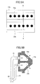
- the separating part 10 may be provided along the entire surface of the cylindrical wall of the cleaning tank 6 and the suction duct 17 may be provided in an outer peripheral part of the separating part 10 as shown in a front cross-sectional view of FIG. 9 .
- the separating part 10 along the entire surface of the cylindrical wall of the cleaning tank 6 so as to increase an area of the separating part 10 formed of a porous member, clogging of the separating part 10 can be prevented and a probability that the cleaning media 5 contact the separating part 10 can be increased.
- a deposit attached on the cleaning media 5 can be efficiently separated and the cleaning medium 5 from which a stain and the like are removed can be collided again with the object 4 to be cleaned.
- a cleaning efficiency of the cleaning apparatus 1 can be improved.
- one set of the cleaning tank unit 2 is provided for the cleaning apparatus 1.
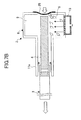
- a description is made below on a cleaning apparatus 1a provided with three sets of cleaning tank units 2a to 2c arranged in series as shown in a configuration diagram of FIG. 10 .
- the three respective sets of the cleaning tank units 2a to 2c have the hollow elongated members 11a and 11b connected to the opposing side walls of the respective cleaning tanks 6.
- the hollow elongated member 11b of the cleaning tank unit 2a and the hollow elongated member 11a of the cleaning tank unit 2b are connected to each other.
- the hollow elongated member 11b of the cleaning tank unit 2b and the hollow elongated member 11a of the cleaning tank unit 2c are connected to each other. In this manner, the cleaning apparatus 1a is constituted.
- the holding part 3 of the cleaning apparatus 1a includes the grip part 21, a wire frame 30, scraper parts 22a and 22b.
- the object 4 to be cleaned is fixed in the holding part 3 by the grip part 21.
- the wire frame 30 has openings in such a size that does not prevent the cleaning medium 5 from passing through.
- the scraper parts 22a and 22b have a feature to allow an air flow to pass through, but not to allow the cleaning medium 5 to pass through.
- the scraper parts 22a and 22b are connected to front and back of the wire frame 30 in a movement direction of the holding part 3.
- the plural cleaning medium accelerating nozzles 13 provided for the cleaning tanks 6 of the cleaning tank units 2a to 2c can have different air injecting directions from each other with respect to the movement direction of the holding part 3.
- the air injecting direction of the cleaning medium accelerating nozzle 13 of the cleaning tank unit 2a is set 90° with respect to the movement direction of the holding part 3.
- the air injecting direction of the cleaning medium accelerating nozzle 13 of the cleaning tank unit 2b is set to 120° with respect to the movement direction of the holding part 3.
- the air injecting direction of the cleaning medium accelerating nozzle 13 of the cleaning tank unit 2c is set to 60° with respect to the movement direction of the holding part 3. In this state, the holding part 3 holding the object 4 to be cleaned is moved from the cleaning tank 2a side.
- the cleaning media 5 can be collided with the object 4 to be cleaned at the different directions even when the object 4 to be cleaned has a complicated shape with protrusions and recessions.
- the object 4 to be cleaned can be cleaned evenly.
- the holding part 3 is not required to be reciprocated, but is only required to be driven in one direction to obtain a required cleaning result.
- the plural holding parts 3 holding the objects 4 to be cleaned can be inserted in succession to be cleaned. As a result, the plural objects 4 to be cleaned can be successively cleaned in a short time.
- the scraper parts 22a and 22b provided at front and back of the holding part 3 can prevent a part of the cleaning media 5 collided with the object 4 from being leaked outside the cleaning tank units 2a to 2c.
- the scraper parts 22a and 22b pushes out the cleaning media 5 accumulated on the hollow elongated members 11a and 11b, thereby the cleaning media 5 can be collected into the cleaning tank 6. Accordingly, an amount of the cleaning media 5 flying in the cleaning tank 6 can be maintained to be constant, and the cleaning performance of the cleaning apparatus 1 can be improved.
- cleaning media can be caused to fly in a cleaning medium flying space without stagnation. Moreover, the cleaning performance can be maintained by effectively using the cleaning media and stabilizing the amount of flying cleaning media.
- an object to be cleaned passes through a hollow elongated member and an opening for the object to be cleaned, is inserted at a position facing a cleaning medium accelerating part, and collided with the accelerated cleaning media to be cleaned.
Landscapes
- Life Sciences & Earth Sciences (AREA)
- Sustainable Development (AREA)
- Physics & Mathematics (AREA)
- General Physics & Mathematics (AREA)
- Engineering & Computer Science (AREA)
- Mechanical Engineering (AREA)
- Cleaning In General (AREA)
- Cleaning By Liquid Or Steam (AREA)
Applications Claiming Priority (2)
| Application Number | Priority Date | Filing Date | Title |
|---|---|---|---|
| JP2008158618 | 2008-06-18 | ||
| JP2009111799A JP5403407B2 (ja) | 2008-06-18 | 2009-05-01 | 洗浄装置 |
Publications (2)
| Publication Number | Publication Date |
|---|---|
| EP2135687A1 true EP2135687A1 (de) | 2009-12-23 |
| EP2135687B1 EP2135687B1 (de) | 2011-08-24 |
Family
ID=40848434
Family Applications (1)
| Application Number | Title | Priority Date | Filing Date |
|---|---|---|---|
| EP09162888A Not-in-force EP2135687B1 (de) | 2008-06-18 | 2009-06-17 | Reinigungsvorrichtung und Reinigungsverfahren |
Country Status (5)
| Country | Link |
|---|---|
| US (1) | US8584312B2 (de) |
| EP (1) | EP2135687B1 (de) |
| JP (1) | JP5403407B2 (de) |
| CN (1) | CN101607254B (de) |
| AT (1) | ATE521422T1 (de) |
Cited By (3)
| Publication number | Priority date | Publication date | Assignee | Title |
|---|---|---|---|---|
| EP2455192A3 (de) * | 2010-11-17 | 2014-11-19 | Ricoh Company, Ltd. | Trockenreinigungsrahmen und Trockenreinigungsvorrichtung |
| WO2020225407A1 (de) * | 2019-05-08 | 2020-11-12 | Ecoclean Gmbh | Reinigungsvorrichtung |
| CN113060190A (zh) * | 2021-04-03 | 2021-07-02 | 李焕冬 | 一种建筑施工用的运输车 |
Families Citing this family (15)
| Publication number | Priority date | Publication date | Assignee | Title |
|---|---|---|---|---|
| JP4770821B2 (ja) * | 2007-11-16 | 2011-09-14 | パナソニック株式会社 | 電気掃除機 |
| JP4531841B2 (ja) * | 2008-02-27 | 2010-08-25 | 株式会社リコー | 洗浄装置及び洗浄方法 |
| JP5793980B2 (ja) | 2010-11-10 | 2015-10-14 | 株式会社リコー | 乾式クリーニング筐体及び乾式クリーニング装置 |
| JP5879903B2 (ja) | 2011-02-25 | 2016-03-08 | 株式会社リコー | 乾式クリーニング筐体、乾式クリーニング装置及び乾式クリーニングシステム |
| JP5953975B2 (ja) | 2011-10-26 | 2016-07-20 | 株式会社リコー | 洗浄媒体飛散防止部材、洗浄対象物保持体及び乾式洗浄装置 |
| JP5919786B2 (ja) | 2011-12-12 | 2016-05-18 | 株式会社リコー | 乾式クリーニング筐体及び乾式クリーニング装置 |
| JP5440622B2 (ja) * | 2012-01-27 | 2014-03-12 | 株式会社リコー | 乾式クリーニング装置及び乾式クリーニング方法 |
| JP6492429B2 (ja) | 2013-10-15 | 2019-04-03 | 株式会社リコー | 乾式クリーニング筐体、乾式クリーニング装置及び分離板の装着方法 |
| KR101375498B1 (ko) * | 2013-11-20 | 2014-04-01 | 김영도 | 신발 내부 세척 및 살균장치 |
| KR101795918B1 (ko) | 2015-07-24 | 2017-11-10 | 주식회사 포스코 | 내시효성 및 소부경화성이 우수한 용융아연도금강판, 합금화 용융아연도금강판 및 그 제조방법 |
| CA2946415C (en) * | 2015-11-11 | 2023-11-07 | Engineered Abrasives, Inc. | Part processing and cleaning apparatus and method of same |
| US10569309B2 (en) * | 2015-12-15 | 2020-02-25 | General Electric Company | Equipment cleaning system and method |
| JP6975953B2 (ja) * | 2016-12-28 | 2021-12-01 | ヒューグル開発株式会社 | 異物除去装置及び異物除去方法 |
| JP6924676B2 (ja) * | 2017-11-08 | 2021-08-25 | アマノ株式会社 | 集塵フード |
| CN107866415A (zh) * | 2017-12-21 | 2018-04-03 | 上海芯湃电子科技有限公司 | 载带除静电清洁装置 |
Citations (6)
| Publication number | Priority date | Publication date | Assignee | Title |
|---|---|---|---|---|
| EP0316622A2 (de) | 1987-11-20 | 1989-05-24 | General Electric Company | Verfahren und Gerät zur Reinigung von polymerischen Harzteilchen |
| US5265298A (en) | 1992-02-25 | 1993-11-30 | Raymond Young | Container cleaning system using ionized air flow |
| JPH1034100A (ja) | 1996-07-30 | 1998-02-10 | Eikichi Yamaharu | 樹脂製容器の清掃方法および装置 |
| WO2006137264A1 (en) | 2005-06-22 | 2006-12-28 | Ricoh Company, Ltd. | Dry cleaning apparatus and method capable of cleaning the cleaning agent |
| EP1782895A1 (de) | 2005-11-02 | 2007-05-09 | Ricoh Company, Ltd. | Vorrichtung und Verfahren zum Trockenreinigen |
| EP1897628A2 (de) | 2006-09-06 | 2008-03-12 | Ricoh Company, Ltd. | Trockenreinigungsvorrichtung und Trockenreinigungsverfahren |
Family Cites Families (16)
| Publication number | Priority date | Publication date | Assignee | Title |
|---|---|---|---|---|
| US1910497A (en) * | 1930-01-02 | 1933-05-23 | American Foundry Equip Co | Sand blast gun |
| US2657409A (en) * | 1949-05-06 | 1953-11-03 | Robert A J Dawson | Rowel type pipe cleaning tool |
| US2649757A (en) * | 1950-07-11 | 1953-08-25 | Edward W Sharpe | Coating device for coating elongated objects |
| US3508997A (en) * | 1966-12-01 | 1970-04-28 | John Mckenney Werling | Method and apparatus for cleaning and reconditioning of material containing cans |
| US5443801A (en) * | 1990-07-20 | 1995-08-22 | Kew Import/Export Inc. | Endoscope cleaner/sterilizer |
| JP2515833Y2 (ja) | 1991-03-27 | 1996-10-30 | スバル興業株式会社 | 飛翔体を用いた清掃装置 |
| JP2582321Y2 (ja) * | 1992-09-03 | 1998-09-30 | 石川島播磨重工業株式会社 | 焼却炉用フィルタの清掃装置 |
| CA2103685C (en) * | 1993-08-06 | 1997-11-11 | Charles P. Elliott | Blast cleaning apparatus and method with laterally moving conveyor |
| JP3373050B2 (ja) | 1994-05-30 | 2003-02-04 | ナミテイ株式会社 | 表面処理装置 |
| JP2791862B2 (ja) | 1994-08-22 | 1998-08-27 | 谷口工業株式会社 | 洗浄篭受け渡し装置 |
| US6034351A (en) * | 1998-06-24 | 2000-03-07 | Sato; Katsuhiro | Cleaning apparatus for welding torch nozzle and method of cleaning the same |
| JP2005296853A (ja) * | 2004-04-13 | 2005-10-27 | Ricoh Co Ltd | 微粉除去装置 |
| FR2900915B1 (fr) * | 2006-05-10 | 2008-12-26 | Financ De Gestion Soc Civ Ile | Bavette d'etancheite pour convoyeur |
| JP4749287B2 (ja) * | 2006-09-06 | 2011-08-17 | 株式会社リコー | 洗浄装置 |
| US7854648B2 (en) * | 2006-12-15 | 2010-12-21 | Ricoh Company, Ltd. | Cleaning medium and dry cleaning apparatus using the same |
| US20090095160A1 (en) * | 2007-10-12 | 2009-04-16 | Ronald Troxell | Electrostatically charged engine intake filter media |
-
2009
- 2009-05-01 JP JP2009111799A patent/JP5403407B2/ja not_active Expired - Fee Related
- 2009-06-15 US US12/484,574 patent/US8584312B2/en not_active Expired - Fee Related
- 2009-06-17 EP EP09162888A patent/EP2135687B1/de not_active Not-in-force
- 2009-06-17 AT AT09162888T patent/ATE521422T1/de not_active IP Right Cessation
- 2009-06-18 CN CN2009101461930A patent/CN101607254B/zh not_active Expired - Fee Related
Patent Citations (7)
| Publication number | Priority date | Publication date | Assignee | Title |
|---|---|---|---|---|
| EP0316622A2 (de) | 1987-11-20 | 1989-05-24 | General Electric Company | Verfahren und Gerät zur Reinigung von polymerischen Harzteilchen |
| US5265298A (en) | 1992-02-25 | 1993-11-30 | Raymond Young | Container cleaning system using ionized air flow |
| JPH1034100A (ja) | 1996-07-30 | 1998-02-10 | Eikichi Yamaharu | 樹脂製容器の清掃方法および装置 |
| WO2006137264A1 (en) | 2005-06-22 | 2006-12-28 | Ricoh Company, Ltd. | Dry cleaning apparatus and method capable of cleaning the cleaning agent |
| JP2007029945A (ja) * | 2005-06-22 | 2007-02-08 | Ricoh Co Ltd | 乾式洗浄装置及び乾式洗浄方法 |
| EP1782895A1 (de) | 2005-11-02 | 2007-05-09 | Ricoh Company, Ltd. | Vorrichtung und Verfahren zum Trockenreinigen |
| EP1897628A2 (de) | 2006-09-06 | 2008-03-12 | Ricoh Company, Ltd. | Trockenreinigungsvorrichtung und Trockenreinigungsverfahren |
Cited By (4)
| Publication number | Priority date | Publication date | Assignee | Title |
|---|---|---|---|---|
| EP2455192A3 (de) * | 2010-11-17 | 2014-11-19 | Ricoh Company, Ltd. | Trockenreinigungsrahmen und Trockenreinigungsvorrichtung |
| WO2020225407A1 (de) * | 2019-05-08 | 2020-11-12 | Ecoclean Gmbh | Reinigungsvorrichtung |
| US12179240B2 (en) | 2019-05-08 | 2024-12-31 | Ecoclean Gmbh | Cleaning apparatus |
| CN113060190A (zh) * | 2021-04-03 | 2021-07-02 | 李焕冬 | 一种建筑施工用的运输车 |
Also Published As
| Publication number | Publication date |
|---|---|
| CN101607254B (zh) | 2011-01-05 |
| EP2135687B1 (de) | 2011-08-24 |
| ATE521422T1 (de) | 2011-09-15 |
| JP2010023025A (ja) | 2010-02-04 |
| JP5403407B2 (ja) | 2014-01-29 |
| CN101607254A (zh) | 2009-12-23 |
| US20090314312A1 (en) | 2009-12-24 |
| US8584312B2 (en) | 2013-11-19 |
Similar Documents
| Publication | Publication Date | Title |
|---|---|---|
| US8584312B2 (en) | Cleaning apparatus and cleaning method | |
| EP2244847B1 (de) | Reinigungsvorrichtung und reinigungsverfahren | |
| EP1782895B1 (de) | Vorrichtung und Verfahren zum Trockenreinigen | |
| JP4758497B2 (ja) | 洗浄装置及び洗浄方法 | |
| US7854648B2 (en) | Cleaning medium and dry cleaning apparatus using the same | |
| EP1897628A2 (de) | Trockenreinigungsvorrichtung und Trockenreinigungsverfahren | |
| JP5061053B2 (ja) | 乾式洗浄装置と乾式洗浄方法とこれにより洗浄された洗浄物及び再生装置の製造方法 | |
| JP4860764B2 (ja) | 洗浄装置及び洗浄方法 | |
| JP5316496B2 (ja) | 洗浄媒体及び洗浄装置 | |
| WO2012115174A1 (en) | Dry-type cleaning chassis, dry-type cleaning device, and dry-type cleaning system | |
| JP5101873B2 (ja) | 洗浄媒体 | |
| JP4954030B2 (ja) | 洗浄媒体及びそれを使用する乾式洗浄装置 | |
| JP5310812B2 (ja) | 洗浄媒体およびこれを用いる乾式洗浄装置 | |
| JP4902399B2 (ja) | 乾式洗浄装置 | |
| JP5218615B2 (ja) | 乾式洗浄装置 | |
| JP2012210617A (ja) | 洗浄装置 | |
| CN103298386A (zh) | 包括具有用于产生振荡气流的可移动表面的单元的真空清洁设备 |
Legal Events
| Date | Code | Title | Description |
|---|---|---|---|
| PUAI | Public reference made under article 153(3) epc to a published international application that has entered the european phase |
Free format text: ORIGINAL CODE: 0009012 |
|
| 17P | Request for examination filed |
Effective date: 20090617 |
|
| AK | Designated contracting states |
Kind code of ref document: A1 Designated state(s): AT BE BG CH CY CZ DE DK EE ES FI FR GB GR HR HU IE IS IT LI LT LU LV MC MK MT NL NO PL PT RO SE SI SK TR |
|
| 17Q | First examination report despatched |
Effective date: 20100520 |
|
| GRAP | Despatch of communication of intention to grant a patent |
Free format text: ORIGINAL CODE: EPIDOSNIGR1 |
|
| GRAS | Grant fee paid |
Free format text: ORIGINAL CODE: EPIDOSNIGR3 |
|
| GRAA | (expected) grant |
Free format text: ORIGINAL CODE: 0009210 |
|
| AK | Designated contracting states |
Kind code of ref document: B1 Designated state(s): AT BE BG CH CY CZ DE DK EE ES FI FR GB GR HR HU IE IS IT LI LT LU LV MC MK MT NL NO PL PT RO SE SI SK TR |
|
| REG | Reference to a national code |
Ref country code: GB Ref legal event code: FG4D |
|
| REG | Reference to a national code |
Ref country code: CH Ref legal event code: EP |
|
| REG | Reference to a national code |
Ref country code: IE Ref legal event code: FG4D |
|
| REG | Reference to a national code |
Ref country code: DE Ref legal event code: R096 Ref document number: 602009002245 Country of ref document: DE Effective date: 20111020 |
|
| REG | Reference to a national code |
Ref country code: NL Ref legal event code: VDEP Effective date: 20110824 |
|
| LTIE | Lt: invalidation of european patent or patent extension |
Effective date: 20110824 |
|
| PG25 | Lapsed in a contracting state [announced via postgrant information from national office to epo] |
Ref country code: IS Free format text: LAPSE BECAUSE OF FAILURE TO SUBMIT A TRANSLATION OF THE DESCRIPTION OR TO PAY THE FEE WITHIN THE PRESCRIBED TIME-LIMIT Effective date: 20111224 Ref country code: PT Free format text: LAPSE BECAUSE OF FAILURE TO SUBMIT A TRANSLATION OF THE DESCRIPTION OR TO PAY THE FEE WITHIN THE PRESCRIBED TIME-LIMIT Effective date: 20111226 Ref country code: LT Free format text: LAPSE BECAUSE OF FAILURE TO SUBMIT A TRANSLATION OF THE DESCRIPTION OR TO PAY THE FEE WITHIN THE PRESCRIBED TIME-LIMIT Effective date: 20110824 Ref country code: NL Free format text: LAPSE BECAUSE OF FAILURE TO SUBMIT A TRANSLATION OF THE DESCRIPTION OR TO PAY THE FEE WITHIN THE PRESCRIBED TIME-LIMIT Effective date: 20110824 Ref country code: SE Free format text: LAPSE BECAUSE OF FAILURE TO SUBMIT A TRANSLATION OF THE DESCRIPTION OR TO PAY THE FEE WITHIN THE PRESCRIBED TIME-LIMIT Effective date: 20110824 Ref country code: FI Free format text: LAPSE BECAUSE OF FAILURE TO SUBMIT A TRANSLATION OF THE DESCRIPTION OR TO PAY THE FEE WITHIN THE PRESCRIBED TIME-LIMIT Effective date: 20110824 Ref country code: NO Free format text: LAPSE BECAUSE OF FAILURE TO SUBMIT A TRANSLATION OF THE DESCRIPTION OR TO PAY THE FEE WITHIN THE PRESCRIBED TIME-LIMIT Effective date: 20111124 Ref country code: HR Free format text: LAPSE BECAUSE OF FAILURE TO SUBMIT A TRANSLATION OF THE DESCRIPTION OR TO PAY THE FEE WITHIN THE PRESCRIBED TIME-LIMIT Effective date: 20110824 |
|
| REG | Reference to a national code |
Ref country code: AT Ref legal event code: MK05 Ref document number: 521422 Country of ref document: AT Kind code of ref document: T Effective date: 20110824 |
|
| PG25 | Lapsed in a contracting state [announced via postgrant information from national office to epo] |
Ref country code: GR Free format text: LAPSE BECAUSE OF FAILURE TO SUBMIT A TRANSLATION OF THE DESCRIPTION OR TO PAY THE FEE WITHIN THE PRESCRIBED TIME-LIMIT Effective date: 20111125 Ref country code: AT Free format text: LAPSE BECAUSE OF FAILURE TO SUBMIT A TRANSLATION OF THE DESCRIPTION OR TO PAY THE FEE WITHIN THE PRESCRIBED TIME-LIMIT Effective date: 20110824 Ref country code: PL Free format text: LAPSE BECAUSE OF FAILURE TO SUBMIT A TRANSLATION OF THE DESCRIPTION OR TO PAY THE FEE WITHIN THE PRESCRIBED TIME-LIMIT Effective date: 20110824 Ref country code: SI Free format text: LAPSE BECAUSE OF FAILURE TO SUBMIT A TRANSLATION OF THE DESCRIPTION OR TO PAY THE FEE WITHIN THE PRESCRIBED TIME-LIMIT Effective date: 20110824 Ref country code: LV Free format text: LAPSE BECAUSE OF FAILURE TO SUBMIT A TRANSLATION OF THE DESCRIPTION OR TO PAY THE FEE WITHIN THE PRESCRIBED TIME-LIMIT Effective date: 20110824 Ref country code: CY Free format text: LAPSE BECAUSE OF FAILURE TO SUBMIT A TRANSLATION OF THE DESCRIPTION OR TO PAY THE FEE WITHIN THE PRESCRIBED TIME-LIMIT Effective date: 20110824 |
|
| PG25 | Lapsed in a contracting state [announced via postgrant information from national office to epo] |
Ref country code: BE Free format text: LAPSE BECAUSE OF FAILURE TO SUBMIT A TRANSLATION OF THE DESCRIPTION OR TO PAY THE FEE WITHIN THE PRESCRIBED TIME-LIMIT Effective date: 20110824 |
|
| PG25 | Lapsed in a contracting state [announced via postgrant information from national office to epo] |
Ref country code: SK Free format text: LAPSE BECAUSE OF FAILURE TO SUBMIT A TRANSLATION OF THE DESCRIPTION OR TO PAY THE FEE WITHIN THE PRESCRIBED TIME-LIMIT Effective date: 20110824 Ref country code: CZ Free format text: LAPSE BECAUSE OF FAILURE TO SUBMIT A TRANSLATION OF THE DESCRIPTION OR TO PAY THE FEE WITHIN THE PRESCRIBED TIME-LIMIT Effective date: 20110824 |
|
| PG25 | Lapsed in a contracting state [announced via postgrant information from national office to epo] |
Ref country code: EE Free format text: LAPSE BECAUSE OF FAILURE TO SUBMIT A TRANSLATION OF THE DESCRIPTION OR TO PAY THE FEE WITHIN THE PRESCRIBED TIME-LIMIT Effective date: 20110824 Ref country code: RO Free format text: LAPSE BECAUSE OF FAILURE TO SUBMIT A TRANSLATION OF THE DESCRIPTION OR TO PAY THE FEE WITHIN THE PRESCRIBED TIME-LIMIT Effective date: 20110824 Ref country code: IT Free format text: LAPSE BECAUSE OF FAILURE TO SUBMIT A TRANSLATION OF THE DESCRIPTION OR TO PAY THE FEE WITHIN THE PRESCRIBED TIME-LIMIT Effective date: 20110824 |
|
| PG25 | Lapsed in a contracting state [announced via postgrant information from national office to epo] |
Ref country code: DK Free format text: LAPSE BECAUSE OF FAILURE TO SUBMIT A TRANSLATION OF THE DESCRIPTION OR TO PAY THE FEE WITHIN THE PRESCRIBED TIME-LIMIT Effective date: 20110824 |
|
| PLBE | No opposition filed within time limit |
Free format text: ORIGINAL CODE: 0009261 |
|
| STAA | Information on the status of an ep patent application or granted ep patent |
Free format text: STATUS: NO OPPOSITION FILED WITHIN TIME LIMIT |
|
| 26N | No opposition filed |
Effective date: 20120525 |
|
| REG | Reference to a national code |
Ref country code: DE Ref legal event code: R097 Ref document number: 602009002245 Country of ref document: DE Effective date: 20120525 |
|
| PG25 | Lapsed in a contracting state [announced via postgrant information from national office to epo] |
Ref country code: MC Free format text: LAPSE BECAUSE OF NON-PAYMENT OF DUE FEES Effective date: 20120630 |
|
| PG25 | Lapsed in a contracting state [announced via postgrant information from national office to epo] |
Ref country code: MK Free format text: LAPSE BECAUSE OF FAILURE TO SUBMIT A TRANSLATION OF THE DESCRIPTION OR TO PAY THE FEE WITHIN THE PRESCRIBED TIME-LIMIT Effective date: 20110824 |
|
| REG | Reference to a national code |
Ref country code: IE Ref legal event code: MM4A |
|
| PG25 | Lapsed in a contracting state [announced via postgrant information from national office to epo] |
Ref country code: ES Free format text: LAPSE BECAUSE OF FAILURE TO SUBMIT A TRANSLATION OF THE DESCRIPTION OR TO PAY THE FEE WITHIN THE PRESCRIBED TIME-LIMIT Effective date: 20111205 Ref country code: IE Free format text: LAPSE BECAUSE OF NON-PAYMENT OF DUE FEES Effective date: 20120617 |
|
| PG25 | Lapsed in a contracting state [announced via postgrant information from national office to epo] |
Ref country code: BG Free format text: LAPSE BECAUSE OF FAILURE TO SUBMIT A TRANSLATION OF THE DESCRIPTION OR TO PAY THE FEE WITHIN THE PRESCRIBED TIME-LIMIT Effective date: 20111124 |
|
| PG25 | Lapsed in a contracting state [announced via postgrant information from national office to epo] |
Ref country code: MT Free format text: LAPSE BECAUSE OF FAILURE TO SUBMIT A TRANSLATION OF THE DESCRIPTION OR TO PAY THE FEE WITHIN THE PRESCRIBED TIME-LIMIT Effective date: 20110824 |
|
| REG | Reference to a national code |
Ref country code: CH Ref legal event code: PL |
|
| PG25 | Lapsed in a contracting state [announced via postgrant information from national office to epo] |
Ref country code: LI Free format text: LAPSE BECAUSE OF NON-PAYMENT OF DUE FEES Effective date: 20130630 Ref country code: CH Free format text: LAPSE BECAUSE OF NON-PAYMENT OF DUE FEES Effective date: 20130630 Ref country code: TR Free format text: LAPSE BECAUSE OF FAILURE TO SUBMIT A TRANSLATION OF THE DESCRIPTION OR TO PAY THE FEE WITHIN THE PRESCRIBED TIME-LIMIT Effective date: 20110824 |
|
| PG25 | Lapsed in a contracting state [announced via postgrant information from national office to epo] |
Ref country code: LU Free format text: LAPSE BECAUSE OF NON-PAYMENT OF DUE FEES Effective date: 20120617 |
|
| PG25 | Lapsed in a contracting state [announced via postgrant information from national office to epo] |
Ref country code: HU Free format text: LAPSE BECAUSE OF FAILURE TO SUBMIT A TRANSLATION OF THE DESCRIPTION OR TO PAY THE FEE WITHIN THE PRESCRIBED TIME-LIMIT Effective date: 20090617 |
|
| REG | Reference to a national code |
Ref country code: FR Ref legal event code: PLFP Year of fee payment: 8 |
|
| REG | Reference to a national code |
Ref country code: FR Ref legal event code: PLFP Year of fee payment: 9 |
|
| REG | Reference to a national code |
Ref country code: FR Ref legal event code: PLFP Year of fee payment: 10 |
|
| PGFP | Annual fee paid to national office [announced via postgrant information from national office to epo] |
Ref country code: DE Payment date: 20180625 Year of fee payment: 10 |
|
| PGFP | Annual fee paid to national office [announced via postgrant information from national office to epo] |
Ref country code: FR Payment date: 20180620 Year of fee payment: 10 |
|
| PGFP | Annual fee paid to national office [announced via postgrant information from national office to epo] |
Ref country code: GB Payment date: 20180620 Year of fee payment: 10 |
|
| REG | Reference to a national code |
Ref country code: DE Ref legal event code: R119 Ref document number: 602009002245 Country of ref document: DE |
|
| GBPC | Gb: european patent ceased through non-payment of renewal fee |
Effective date: 20190617 |
|
| PG25 | Lapsed in a contracting state [announced via postgrant information from national office to epo] |
Ref country code: GB Free format text: LAPSE BECAUSE OF NON-PAYMENT OF DUE FEES Effective date: 20190617 Ref country code: DE Free format text: LAPSE BECAUSE OF NON-PAYMENT OF DUE FEES Effective date: 20200101 |
|
| PG25 | Lapsed in a contracting state [announced via postgrant information from national office to epo] |
Ref country code: FR Free format text: LAPSE BECAUSE OF NON-PAYMENT OF DUE FEES Effective date: 20190630 |