EP2136558A2 - Informationsverarbeitungsvorrichtung und Informationsverarbeitungsverfahren und Speichermedium - Google Patents
Informationsverarbeitungsvorrichtung und Informationsverarbeitungsverfahren und Speichermedium Download PDFInfo
- Publication number
- EP2136558A2 EP2136558A2 EP09162980A EP09162980A EP2136558A2 EP 2136558 A2 EP2136558 A2 EP 2136558A2 EP 09162980 A EP09162980 A EP 09162980A EP 09162980 A EP09162980 A EP 09162980A EP 2136558 A2 EP2136558 A2 EP 2136558A2
- Authority
- EP
- European Patent Office
- Prior art keywords
- frequency
- video signal
- information processing
- video signals
- scanning
- Prior art date
- Legal status (The legal status is an assumption and is not a legal conclusion. Google has not performed a legal analysis and makes no representation as to the accuracy of the status listed.)
- Withdrawn
Links
Images


Classifications
-
- H—ELECTRICITY
- H04—ELECTRIC COMMUNICATION TECHNIQUE
- H04N—PICTORIAL COMMUNICATION, e.g. TELEVISION
- H04N7/00—Television systems
- H04N7/01—Conversion of standards, e.g. involving analogue television standards or digital television standards processed at pixel level
-
- G—PHYSICS
- G09—EDUCATION; CRYPTOGRAPHY; DISPLAY; ADVERTISING; SEALS
- G09G—ARRANGEMENTS OR CIRCUITS FOR CONTROL OF INDICATING DEVICES USING STATIC MEANS TO PRESENT VARIABLE INFORMATION
- G09G3/00—Control arrangements or circuits, of interest only in connection with visual indicators other than cathode-ray tubes
- G09G3/20—Control arrangements or circuits, of interest only in connection with visual indicators other than cathode-ray tubes for presentation of an assembly of a number of characters, e.g. a page, by composing the assembly by combination of individual elements arranged in a matrix no fixed position being assigned to or needed to be assigned to the individual characters or partial characters
- G09G3/34—Control arrangements or circuits, of interest only in connection with visual indicators other than cathode-ray tubes for presentation of an assembly of a number of characters, e.g. a page, by composing the assembly by combination of individual elements arranged in a matrix no fixed position being assigned to or needed to be assigned to the individual characters or partial characters by control of light from an independent source
- G09G3/36—Control arrangements or circuits, of interest only in connection with visual indicators other than cathode-ray tubes for presentation of an assembly of a number of characters, e.g. a page, by composing the assembly by combination of individual elements arranged in a matrix no fixed position being assigned to or needed to be assigned to the individual characters or partial characters by control of light from an independent source using liquid crystals
- G09G3/3611—Control of matrices with row and column drivers
- G09G3/3648—Control of matrices with row and column drivers using an active matrix
- G09G3/3666—Control of matrices with row and column drivers using an active matrix with the matrix divided into sections
-
- H—ELECTRICITY
- H04—ELECTRIC COMMUNICATION TECHNIQUE
- H04N—PICTORIAL COMMUNICATION, e.g. TELEVISION
- H04N21/00—Selective content distribution, e.g. interactive television or video on demand [VOD]
- H04N21/40—Client devices specifically adapted for the reception of or interaction with content, e.g. set-top-box [STB]; Operations thereof
- H04N21/43—Processing of content or additional data, e.g. demultiplexing additional data from a digital video stream; Elementary client operations, e.g. monitoring of home network or synchronising decoder's clock; Client middleware
- H04N21/4302—Content synchronisation processes, e.g. decoder synchronisation
-
- H—ELECTRICITY
- H04—ELECTRIC COMMUNICATION TECHNIQUE
- H04N—PICTORIAL COMMUNICATION, e.g. TELEVISION
- H04N21/00—Selective content distribution, e.g. interactive television or video on demand [VOD]
- H04N21/40—Client devices specifically adapted for the reception of or interaction with content, e.g. set-top-box [STB]; Operations thereof
- H04N21/43—Processing of content or additional data, e.g. demultiplexing additional data from a digital video stream; Elementary client operations, e.g. monitoring of home network or synchronising decoder's clock; Client middleware
- H04N21/431—Generation of visual interfaces for content selection or interaction; Content or additional data rendering
- H04N21/4312—Generation of visual interfaces for content selection or interaction; Content or additional data rendering involving specific graphical features, e.g. screen layout, special fonts or colors, blinking icons, highlights or animations
- H04N21/4314—Generation of visual interfaces for content selection or interaction; Content or additional data rendering involving specific graphical features, e.g. screen layout, special fonts or colors, blinking icons, highlights or animations for fitting data in a restricted space on the screen, e.g. EPG data in a rectangular grid
-
- H—ELECTRICITY
- H04—ELECTRIC COMMUNICATION TECHNIQUE
- H04N—PICTORIAL COMMUNICATION, e.g. TELEVISION
- H04N21/00—Selective content distribution, e.g. interactive television or video on demand [VOD]
- H04N21/40—Client devices specifically adapted for the reception of or interaction with content, e.g. set-top-box [STB]; Operations thereof
- H04N21/43—Processing of content or additional data, e.g. demultiplexing additional data from a digital video stream; Elementary client operations, e.g. monitoring of home network or synchronising decoder's clock; Client middleware
- H04N21/431—Generation of visual interfaces for content selection or interaction; Content or additional data rendering
- H04N21/4312—Generation of visual interfaces for content selection or interaction; Content or additional data rendering involving specific graphical features, e.g. screen layout, special fonts or colors, blinking icons, highlights or animations
- H04N21/4316—Generation of visual interfaces for content selection or interaction; Content or additional data rendering involving specific graphical features, e.g. screen layout, special fonts or colors, blinking icons, highlights or animations for displaying supplemental content in a region of the screen, e.g. an advertisement in a separate window
-
- H—ELECTRICITY
- H04—ELECTRIC COMMUNICATION TECHNIQUE
- H04N—PICTORIAL COMMUNICATION, e.g. TELEVISION
- H04N21/00—Selective content distribution, e.g. interactive television or video on demand [VOD]
- H04N21/40—Client devices specifically adapted for the reception of or interaction with content, e.g. set-top-box [STB]; Operations thereof
- H04N21/43—Processing of content or additional data, e.g. demultiplexing additional data from a digital video stream; Elementary client operations, e.g. monitoring of home network or synchronising decoder's clock; Client middleware
- H04N21/44—Processing of video elementary streams, e.g. splicing a video clip retrieved from local storage with an incoming video stream or rendering scenes according to encoded video stream scene graphs
- H04N21/4402—Processing of video elementary streams, e.g. splicing a video clip retrieved from local storage with an incoming video stream or rendering scenes according to encoded video stream scene graphs involving reformatting operations of video signals for household redistribution, storage or real-time display
- H04N21/440281—Processing of video elementary streams, e.g. splicing a video clip retrieved from local storage with an incoming video stream or rendering scenes according to encoded video stream scene graphs involving reformatting operations of video signals for household redistribution, storage or real-time display by altering the temporal resolution, e.g. by frame skipping
-
- H—ELECTRICITY
- H04—ELECTRIC COMMUNICATION TECHNIQUE
- H04N—PICTORIAL COMMUNICATION, e.g. TELEVISION
- H04N21/00—Selective content distribution, e.g. interactive television or video on demand [VOD]
- H04N21/40—Client devices specifically adapted for the reception of or interaction with content, e.g. set-top-box [STB]; Operations thereof
- H04N21/47—End-user applications
-
- H—ELECTRICITY
- H04—ELECTRIC COMMUNICATION TECHNIQUE
- H04N—PICTORIAL COMMUNICATION, e.g. TELEVISION
- H04N5/00—Details of television systems
- H04N5/04—Synchronising
-
- H—ELECTRICITY
- H04—ELECTRIC COMMUNICATION TECHNIQUE
- H04N—PICTORIAL COMMUNICATION, e.g. TELEVISION
- H04N5/00—Details of television systems
- H04N5/44—Receiver circuitry for the reception of television signals according to analogue transmission standards
- H04N5/445—Receiver circuitry for the reception of television signals according to analogue transmission standards for displaying additional information
- H04N5/45—Picture in picture, e.g. displaying simultaneously another television channel in a region of the screen
-
- G—PHYSICS
- G06—COMPUTING OR CALCULATING; COUNTING
- G06F—ELECTRIC DIGITAL DATA PROCESSING
- G06F3/00—Input arrangements for transferring data to be processed into a form capable of being handled by the computer; Output arrangements for transferring data from processing unit to output unit, e.g. interface arrangements
- G06F3/14—Digital output to display device ; Cooperation and interconnection of the display device with other functional units
-
- G—PHYSICS
- G09—EDUCATION; CRYPTOGRAPHY; DISPLAY; ADVERTISING; SEALS
- G09G—ARRANGEMENTS OR CIRCUITS FOR CONTROL OF INDICATING DEVICES USING STATIC MEANS TO PRESENT VARIABLE INFORMATION
- G09G2340/00—Aspects of display data processing
- G09G2340/04—Changes in size, position or resolution of an image
- G09G2340/0407—Resolution change, inclusive of the use of different resolutions for different screen areas
- G09G2340/0435—Change or adaptation of the frame rate of the video stream
-
- G—PHYSICS
- G09—EDUCATION; CRYPTOGRAPHY; DISPLAY; ADVERTISING; SEALS
- G09G—ARRANGEMENTS OR CIRCUITS FOR CONTROL OF INDICATING DEVICES USING STATIC MEANS TO PRESENT VARIABLE INFORMATION
- G09G2340/00—Aspects of display data processing
- G09G2340/12—Overlay of images, i.e. displayed pixel being the result of switching between the corresponding input pixels
-
- G—PHYSICS
- G09—EDUCATION; CRYPTOGRAPHY; DISPLAY; ADVERTISING; SEALS
- G09G—ARRANGEMENTS OR CIRCUITS FOR CONTROL OF INDICATING DEVICES USING STATIC MEANS TO PRESENT VARIABLE INFORMATION
- G09G2352/00—Parallel handling of streams of display data
-
- H—ELECTRICITY
- H04—ELECTRIC COMMUNICATION TECHNIQUE
- H04N—PICTORIAL COMMUNICATION, e.g. TELEVISION
- H04N7/00—Television systems
- H04N7/01—Conversion of standards, e.g. involving analogue television standards or digital television standards processed at pixel level
- H04N7/0127—Conversion of standards, e.g. involving analogue television standards or digital television standards processed at pixel level by changing the field or frame frequency of the incoming video signal, e.g. frame rate converter
Definitions
- the present invention relates to an information processing device and an information processing method, and a storage medium having stored therein a program, and, more particularly, to an information processing device and an information processing method that can display video signals having different scanning frequencies separately from one another on a single display, and a storage medium having stored therein a program.
- Video signals that have been subjected to various types of internal conversion such as scanning-frequency conversion are displayed as videos that appear visually different from one another. Accordingly, in the related art, in order to simultaneously compare the videos with one another, typically, the respective videos are displayed on a plurality of displays.
- An information processing device includes the following elements: an input section configured to input a plurality of types of video signals; and a timing controller configured to perform, separately for each of split regions that are obtained by splitting a display region of a display device, control of timing at which a corresponding one of videos corresponding to the plurality of types of video signals is displayed in the split region.
- the display device may be a pixel-type display device. Displaying with display elements constituting the pixel-type display device may be controlled by driving source drivers and gate drivers. Each of the source drivers and each of the gate drivers may be assigned to a corresponding one of the split regions. The timing controller may control, for each of the split regions, timing at which a corresponding one of the source drivers and a corresponding one of the gate drivers are driven.
- N split regions may exist as the split regions (wherein n is an integer value that is equal to or larger than two).
- Each of the gate drivers may be assigned as a gate driver for a corresponding one of the n split regions.
- One of the source drivers may be assigned as a source driver for a group of x split regions among the n split regions (wherein x is an integer value that is equal to or larger than two and that is equal to or smaller than n).
- Each of the gate drivers may be assigned to a corresponding one of the x split regions to which the source driver is assigned.
- the timing controller may perform control of supplying signals from the source driver to the gate drivers in respective horizontal one-line drive periods of the gate drivers in such a manner that the signals are divided using time division and prohibited from overlapping one another.
- the plurality of types of video signals may include two or more video signals having different scanning frequencies.
- the information processing device may further include a conversion section configured to convert a scanning frequency of an input video signal.
- the conversion section may convert the scanning frequency of the input video signal using a plurality of techniques as techniques for converting the scanning frequency of the input video signal, and may select, from among a plurality of types of video signals that are obtained as a result of conversion, a video signal that is to be displayed in each of the split regions.
- An information processing method and a storage medium having stored therein a program according to embodiments of the present invention are a method and a storage medium that each correspond to the above-described information processing device according to the embodiment of the present invention.
- video signals having different scanning frequencies can be displayed separately from one another on a single display device (a display).
- the video signal having different scanning frequencies can be compared with one another on the single display having the same characteristics.
- Fig. 1 is a block diagram showing an example of a configuration of an information processing device of the related art.
- the information processing device of the related art of the example shown in Fig. 1 includes a main control section 1, a scanning-frequency conversion section 2, a timing control section 3, a source driver 4, a gate driver 5, and a thin film transistor (TFT) liquid crystal display panel 6. Furthermore, the scanning-frequency conversion section 2 includes selection units 11, 13, and 14, a 24 to 60 Hz conversion unit 12, a 24 to 120 Hz conversion unit 15 (that outputs a video signal five times in a period corresponding to a frequency of 24 Hz), a 60 to 120 Hz conversion unit 16 (that outputs a video signal twice in a period corresponding to a frequency of 60 Hz), and a 60 to 120 Hz conversion unit 17 (that generates frames).
- the scanning-frequency conversion section 2 includes selection units 11, 13, and 14, a 24 to 60 Hz conversion unit 12, a 24 to 120 Hz conversion unit 15 (that outputs a video signal five times in a period corresponding to a frequency of 24 Hz), a 60 to 120 Hz conversion unit 16 (that outputs a video signal
- Input video signals (having frequencies of 24 Hz and 60 Hz in the example shown in Fig. 1 ) are input to the selection unit 11 that is provided in the scanning-frequency conversion section 2.
- the selection unit 11 selects, in accordance with control performed by the main control section 1, the 24 to 60 Hz conversion unit 12 or the 24 to 120 Hz conversion unit 15 as a unit to which the input video signal having a frequency of 24 Hz is to be output.
- the input video signal having a frequency of 24 Hz is supplied to the 24 to 60 Hz conversion unit 12 or the 24 to 120 Hz conversion unit 15.
- the selection unit 11 selects the selection unit 13 or 14 as a unit to which the input video signal having a frequency of 60 Hz is to be output. In other words, the input video signal having a frequency of 60 Hz is supplied to the selection unit 13 or 14.
- the 24 to 60 Hz conversion unit 12 converts the scanning frequency of the input video signal having a frequency of 24 Hz that is supplied from the selection unit 11 into 60 Hz to obtain a video signal having a frequency of 60 Hz. Then, the 24 to 60 Hz conversion unit 12 supplies the video signal having a frequency of 60 Hz to the selection units 13 and 14.
- the input video signal having a frequency of 60 Hz and the video signal having a frequency of 60 Hz that was converted from the input video signal having a frequency of 24 Hz are input to the selection unit 13.
- the selection unit 13 selects, in accordance with control performed by the main control section 1, one of the two input video signals having a frequency of 60 Hz, and supplies the selected video signal to the 60 to 120 Hz conversion unit 16.
- the input video signal having a frequency of 60 Hz and the video signal that was converted from the input video signal having a frequency of 24 Hz are input to the selection unit 14.
- the selection unit 14 selects, in accordance with control performed by the main control section 1, one of the two input video signals having a frequency of 60 Hz, and supplies the selected video signal to the 60 to 120 Hz conversion unit 17.
- the 24 to 120 Hz conversion unit 15 converts the scanning frequency of the input video signal having a frequency of 24 Hz into 120 Hz to obtain a video signal having a frequency of 120 Hz. Then, the 24 to 120 Hz conversion unit 15 supplies the video signal having a frequency of 120 Hz to the timing control section 3. Note that, as a conversion technique that is performed by the 24 to 120 Hz conversion unit 15, a technique is employed, in which frames constituting the video signal having a frequency of 24 Hz are output five times in a period corresponding to the frequency of 24 Hz, thereby converting the video signal having a frequency of 24 Hz into a video signal having a frequency of 120 Hz, as described in brackets shown in Fig. 1 .
- the 60 to 120 Hz conversion unit 16 converts the scanning frequency of the input video signal having a frequency of 60 Hz into 120 Hz to obtain a video signal having a frequency of 120 Hz. Then, the 60 to 120 Hz conversion unit 16 supplies the video signal having a frequency of 120 Hz to the timing control section 3. Note that, as a conversion technique that is performed by the 60 to 120 Hz conversion unit 16, a technique is employed, in which frames constituting the video signal having a frequency of 60 Hz are output twice in a period corresponding to the frequency of 60 Hz, thereby converting the video signal having a frequency of 60 Hz into a video signal having a frequency of 120 Hz, as described in brackets shown in Fig. 1 .
- the 60 to 120 Hz conversion unit 17 converts the scanning frequency of the input video signal having a frequency of 60 Hz into 120 Hz to obtain a video signal having a frequency of 120 Hz. Then, the 60 to 120 Hz conversion unit 17 supplies the video signal having a frequency of 120 Hz to the timing control section 3.
- a technique is employed, in which new frames are predicted and generated using an appropriate technique on the basis of the video signal having a frequency of 60 Hz, and in which the new frames are inserted between respective frames constituting the input video signal having a frequency of 60 Hz, thereby converting the video signal having a frequency of 60 Hz into a video signal having a frequency of 120 Hz, as described in brackets shown in Fig. 1 .
- the timing control section 3 supplies the supplied input video signals having a frequency of 120 Hz to the source driver 4 and the gate driver 5. Accordingly, videos corresponding to the input video signals having a frequency of 120 Hz are displayed on the TFT liquid crystal display panel 6 in accordance with control that is performed by the source driver 4 and the gate driver 5.
- a display of the related art to which video signals having different frequencies can be input performs internal conversion so that the scanning frequencies of output video signals are set to a fixed value regardless of the scanning frequencies of the input video signals, and displays the output video signals.
- Examples of internal conversion include internal conversion in which internal format conversion is simply performed, and internal conversion that involves signal processing such as scanning-frequency conversion as in the above-described example.
- internal conversion in which frames are repeatedly displayed, such as 2-3 pull down or 2-2 pull down, a technique in which frames to be inserted are predicted and generated, and so forth exist as techniques for scanning-frequency conversion.
- a blurred afterimage that is caused because a response speed is not sufficient is considered as one of problems of a liquid crystal display.
- a technique has also been developed, in which the scanning frequency of a video signal is converted into a frequency that is equal to or higher than a frequency of the video signal at a point in time at which the video signal is input, and in which the video signal is output. Accordingly, videos corresponding to video signals whose scanning frequencies have been converted using various types of internal conversion such as scanning-frequency conversion appear visually different from one another.
- Two techniques i.e., a technique in which a plurality of displays that are driven at different scanning frequencies are disposed, and a technique in which videos are displayed separately from one another on a single display, exist as techniques of the related art for comparing and evaluating video signals having different scanning frequencies.
- a technique in which one display is formed by bonding displays that are driven at different scanning frequencies together.
- a space in which a driver is disposed is necessary for each of the displays, and, as the degree of parallelism of the displays is increased, it is difficult to form a single display having no physical boundary.
- the displays have individual differences, and compensation for the characteristics of viewing angle is also important. An extra task of standardizing the characteristics of the displays so that the displays have the same quality is necessary, and accurate comparison is difficult.
- Fig. 2 is a functional block diagram showing an example of a configuration of an information processing device according to an embodiment of the present invention.
- the information processing device of the example shown in Fig. 2 includes a scanning-frequency conversion section 21, a timing control section 22, a source driver 23, a gate driver 24, and a TFT liquid crystal display panel 25.
- An input video signal having a scanning frequency of fin Hz is input to the scanning-frequency conversion section 21.
- the scanning-frequency conversion section 21 converts a scanning frequency of fin Hz that is the scanning frequency of the input video signal into scanning frequencies of f1 Hz to fn Hz (wherein n is an integer value that is equal to or larger than two) to obtain video signals having the scanning frequencies of f1 Hz to fn Hz.
- the scanning-frequency conversion section 21 supplies the respective video signals having the scanning frequencies of f1 Hz to fn Hz to the timing control section 22.
- a scanning frequency of fp Hz (wherein p is any integer value from one to n) and a scanning frequency of fq Hz (wherein q is any integer value from one to n other than p) are not necessarily different frequencies.
- a scanning-frequency conversion technique that is used for internal conversion which is performed by the scanning-frequency conversion section 21 may be different for each of the scanning frequencies of fp Hz and fq Hz.
- the timing control section 22 performs conversion on each of the video signals having the scanning frequencies of f1 Hz to fn Hz in order to be suitable for an arbitrary scanning frequency and a panel input interface. Then, the timing control section 22 supplies, to the source driver 23 and the gate driver 24, respective video signals that are obtained by conversion.
- the TFT liquid crystal display panel 25 can simultaneously display, in accordance with control that is performed by the source driver 23 and the gate driver 24, the video signals that are obtained using different scanning-frequency conversion techniques in respective display regions that are obtained by splitting a single display screen.
- the number of pixels of the TFT liquid crystal display panel 25 is not sufficient for the total number of pixels that form the input video signal having the scanning frequency of fin Hz and the number of display regions using split screen, it is necessary to include a buffer in the scanning-frequency conversion section 21 or the timing control section 22, and to display video signals that are stored in the buffer in arbitrary frames constituting the input video signal having the scanning frequency of fin Hz.
- Fig. 3 is a functional block diagram showing a detailed example of a functional configuration of the information processing device of the example shown in Fig. 2 .
- the number of display regions n using split screen of the TFT liquid crystal display panel 25 is four.
- each of the scanning frequencies of input video signals is converted from 24 Hz or 60 Hz to 24 Hz, 60 Hz, or 120 Hz.
- a source driver 23-k (wherein k is an integer value from one to n) and a gate driver 24-k are considered as a pair
- the TFT liquid crystal display panel 25 includes n, which is equal to the number of display regions n using split screen, pairs of the source driver 23-k and the gate driver 24-k.
- the information processing device of the example shown in Fig. 3 includes a main control section 41, the scanning-frequency conversion section 21, timing control sections 22-1 to 22-4, the source drivers 23-1 to 23-4, the gate drivers 24-1 to 24-4, and the TFT liquid crystal display panel 25.
- the scanning-frequency conversion section 21 includes selection units 51, 53, 54, 55, and 59, a 24 to 60 Hz conversion unit 52, a 24 to 120 Hz conversion unit 56 (that outputs a video signal five times in a period corresponding to a frequency of 24 Hz), a 60 to 120 Hz conversion unit 57 (that outputs a video signal twice in a period corresponding to a frequency of 60 Hz), and a 60 to 120 Hz conversion unit 58 (that generates frames).
- Input video signals (having frequencies of 24 Hz and 60 Hz in the example shown in Fig. 3 ) are input to the selection unit 51 that is provided in the scanning-frequency conversion section 21.
- the selection unit 51 selects, in accordance with control performed by the main control section 41, one unit from among the selection unit 59, the 24 to 120 Hz conversion unit 56, and the 24 to 60 Hz conversion unit 52 as a unit to which the input video signal having a frequency of 24 Hz is to be output.
- the input video signal having a frequency of 24 Hz is supplied to the selection unit 59, the 24 to 60 Hz conversion unit 52, or the 24 to 120 Hz conversion unit 56.
- the 24 to 60 Hz conversion unit 52 converts the scanning frequency of the input video signal having a frequency of 24 Hz that is supplied from the selection unit 51 into 60 Hz to obtain a video signal having a frequency of 60 Hz. Then, the 24 to 60 Hz conversion unit 52 supplies the video signal having a frequency of 60 Hz to the selection units 53 and 54.
- the selection unit 53 selects the selection unit 59 or 55 as a unit to which the video signal having a frequency of 60 Hz that was converted from the input video signal having a frequency of 24 Hz. In other words, the input video signal having a frequency of 60 Hz is supplied to the selection unit 59 or 55.
- the input video signal having a frequency of 60 Hz and the video signal having a frequency of 60 Hz that was converted from the input video signal having a frequency of 24 Hz are input to the selection unit 54.
- the selection unit 54 selects, in accordance with control performed by the main control section 41, one of the two input video signals having a frequency of 60 Hz, and supplies the selected video signal to the 60 to 120 Hz conversion unit 58.
- the input video signal having a frequency of 60 Hz and the video signal having a frequency of 60 Hz that was converted from the input video signal having a frequency of 24 Hz are input to the selection unit 55.
- the selection unit 55 selects, in accordance with control performed by the main control section 41, one of the two input video signals having a frequency of 60 Hz, and supplies the selected video signal to the 60 to 120 Hz conversion unit 57.
- the 24 to 120 Hz conversion unit 56 converts the scanning frequency of the input video signal having a frequency of 24 Hz into 120 Hz to obtain a video signal having a frequency of 120 Hz. Then, the 24 to 120 Hz conversion unit 56 supplies the video signal having a frequency of 120 Hz to the selection unit 59. Note that, as a conversion technique that is performed by the 24 to 120 Hz conversion unit 56, a technique is employed, in which frames constituting the video signal having a frequency of 24 Hz are output five times in a period corresponding to the frequency of 24 Hz, thereby converting the video signal having a frequency of 24 Hz into a video signal having a frequency of 120 Hz, as described in brackets shown in Fig. 3 .
- the 60 to 120 Hz conversion unit 57 converts the scanning frequency of the input video signal having a frequency of 60 Hz into 120 Hz to obtain a video signal having a frequency of 120 Hz. Then, the 60 to 120 Hz conversion unit 57 supplies the video signal having a frequency of 120 Hz to the selection unit 59. Note that, as a conversion technique that is performed by the 60 to 120 Hz conversion unit 57, a technique is employed, in which frames constituting the video signal having a frequency of 60 Hz are output twice in a period corresponding to the frequency of 60 Hz, thereby converting the video signal having a frequency of 60 Hz into a video signal having a frequency of 120 Hz, as described in brackets shown in Fig. 3 .
- the 60 to 120 Hz conversion unit 58 converts the scanning frequency of the input video signal having a frequency of 60 Hz into 120 Hz to obtain a video signal having a frequency of 120 Hz. Then, the 60 to 120 Hz conversion unit 58 supplies the video signal having a frequency of 120 Hz to the selection unit 59.
- a technique is employed, in which new frames are predicted and generated using an appropriate technique on the basis of the video signal having a frequency of 60 Hz, and in which the new frames are inserted between respective frames constituting the video signal having a frequency of 60 Hz, thereby converting the video signal having a frequency of 60 Hz into a video signal having a frequency of 120 Hz, as described in brackets shown in Fig. 3 .
- the selection unit 59 selectively supplies, in accordance with control performed by the main control section 41, some of the eight types of video signals as video signals having the scanning frequencies of f1 Hz to f4 Hz to the respective timing control sections 22-1 to 22-4.
- the timing control section 22-1 supplies the supplied video signal having the scanning frequency of f1 Hz to the pair of the source driver 23-1 and the gate driver 24-1. Accordingly, a video corresponding to the input video signal having the scanning frequency of f1 Hz is displayed, in accordance with control performed by the pair of the source driver 23-1 and the gate driver 24-1, in an upper-left display region among display regions that are obtained by splitting the display screen of the TFT liquid crystal display panel 25 in four.
- the timing control section 22-2 supplies the supplied video signal having the scanning frequency of f2 Hz to the pair of the source driver 23-2 and the gate driver 24-2. Accordingly, a video corresponding to the input video signal having the scanning frequency of f2 Hz is displayed, in accordance with control performed by the pair of the source driver 23-2 and the gate driver 24-2, in an upper-right display region among the display regions that are obtained by splitting the display screen of the TFT liquid crystal display panel 25 in four.
- the timing control section 22-3 supplies the supplied video signal having the scanning frequency of f3 Hz to the pair of the source driver 23-3 and the gate driver 24-3. Accordingly, a video corresponding to the input video signal having the scanning frequency of f3 Hz is displayed, in accordance with control performed by the pair of the source driver 23-3 and the gate driver 24-3, in a lower-left display region among the display regions that are obtained by splitting the display screen of the TFT liquid crystal display panel 25 in four.
- the timing control section 22-4 supplies the supplied video signal having the scanning frequency of f4 Hz to the pair of the source driver 23-4 and the gate driver 24-4. Accordingly, a video corresponding to the input video signal having the scanning frequency of f4 Hz is displayed, in accordance with control performed by the pair of the source driver 23-4 and the gate driver 24-4, in a lower-right display region among the display regions that are obtained by splitting the display screen of the TFT liquid crystal display panel 25 in four.
- one source driver 23-k and one gate driver 24-k are considered as a pair, and four, which is equal to the number of display regions using split screen, pairs of the source driver 23-k and the gate driver 24-k can be applied to drive the TFT liquid crystal display panel 25.
- each of the video signals having different scanning frequencies can be input to a corresponding one of the pairs. Accordingly, the video signals having different scanning frequencies can be displayed in the respective display regions that are obtained by splitting the display screen of the single TFT liquid crystal display panel 25 having the same characteristics in four.
- the video signals having different scanning frequencies broadly include not only video signals in a case in which the scanning frequencies are different from one another but also video signals in a case in which methods for converting the scanning frequencies such as internal conversion are different from one another even when the scanning frequencies are the same.
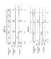
- Fig. 4 is a timing diagram for explaining the example in which the pair of the source driver 23-1 and the gate driver 24-1 is driven.
- a timing chart with an item "Source 23-1 Data” that is shown in the top row of Fig. 4 is a timing chart of data that is to be written into the source driver 23-1, i.e., data corresponding to the video signal having the scanning frequency of f1 Hz.
- a timing chart with an item "Source 23-1 Load” that is shown in the middle row of Fig. 4 is a timing chart of a signal showing a load state (on-state/off-state) of the source driver 23-1.
- a timing chart with an item “Gate 24-1” that is shown in the bottom row of Fig. 4 is a timing chart of a signal showing a state (on-state/off-state) of the gate driver 24-1.
- a period A-1 which is one horizontal drive period 1Hf1 from a time t1 to a time t3, the following operations are performed. More specifically, at the time t1, the load state of the source driver 23-1 is set to the on-state. While the on-state is continuing, data Df1 is written into the source driver 23-1. In other words, when the load state of the source driver 23-1 is set to the off-state, writing of the data Df1 into the source driver 23-1 finishes. Then, at the time t2, the state of the gate driver 24-1 is set to the on-state. Accordingly, the data Df1 that is written into the source driver 23-1 is sequentially output in a period from the time t2 to the time t3.
- Fig. 5 is a timing diagram for explaining the example in which the pair of the source driver 23-3 and the gate driver 24-3 is driven.
- a timing chart with an item "Source 23-3 Data” that is shown in the top row of Fig. 5 is a timing chart of data that is to be written into the source driver 23-3, i.e., data corresponding to the video signal having the scanning frequency of f3 Hz.
- a timing chart with an item "Source 23-3 Load” that is shown in the middle row of Fig. 5 is a timing chart of a signal showing a load state (on-state/off-state) of the source driver 23-3.
- a timing chart with an item “Gate 24-3” that is shown in the bottom row of Fig. 5 is a timing chart of a signal showing a state (on-state/off-state) of the gate driver 24-3.
- a period B-1 which is one horizontal drive period 1Hf3 from the time t1 to the time t4 (for example, that is a period which is twice longer than one horizontal drive period 1Hf1 shown in Fig. 4 ).
- the load state of the source driver 23-3 is set to the on-state. While the on-state is continuing, data Df3 is written into the source driver 23-3. In other words, when the load state of the source driver 23-3 is set to the off-state, writing of the data Df3 into the source driver 23-3 finishes.
- the state of the gate driver 24-3 is set to the on-state. Accordingly, the data Df3 that is written into the source driver 23-3 is sequentially output in a period from the time t11 to the time t4.
- the video signals that are to be displayed in the respective display regions which are obtained by splitting the display screen of the TFT liquid crystal display panel 25 in four, i.e., the video signals having the different scanning frequencies, are driven separately from one another.
- n 4 holds true regarding the number of display regions n using split screen in the present embodiment, the number of display regions is not limited to four.
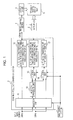
- Fig. 6 is a functional block diagram showing a detailed example, which is different from the example shown in Fig. 3 , of the functional configuration of the information processing device of the example shown in Fig. 2 .
- each of the scanning frequencies of input video signals is converted from 24 Hz or 60 Hz to 24 Hz, 60 Hz, or 120 Hz.
- the ratio of the number of source drivers 23 that are included in the TFT liquid crystal display panel 25 to the number of gate drivers 24 that are included in the TFT liquid crystal display panel 25 is 1:1 in the example shown in Fig. 3
- the ratio is 1:2 in the example shown in Fig. 6 .
- the four gate drivers 24-1 to 24-4 are provided for two source drivers 23-13 and 23-24 on the TFT liquid crystal display panel 25.
- the timing control section 22-1 supplies the supplied video signal having the scanning frequency of f1 Hz to the source driver 23-13 and the gate driver 24-1. Accordingly, a video corresponding to the input video signal having the scanning frequency of f1 Hz is displayed, in accordance with control performed by the source driver 23-13 and the gate driver 24-1, in the upper-left display region among the display regions that are obtained by splitting the display screen of the TFT liquid crystal display panel 25 in four.
- the timing control section 22-2 supplies the supplied video signal having the scanning frequency of f2 Hz to the source driver 23-24 and the gate driver 24-2. Accordingly, a video corresponding to the input video signal having the scanning frequency of f2 Hz is displayed, in accordance with control performed by the source driver 23-24 and the gate driver 24-2, in the upper-right display region among the display regions that are obtained by splitting the display screen of the TFT liquid crystal display panel 25 in four.
- the timing control section 22-3 supplies the supplied video signal having the scanning frequency of f3 Hz to the source driver 23-13 and the gate driver 24-3. Accordingly, a video corresponding to the input video signal having the scanning frequency of f3 Hz is displayed, in accordance with control performed by the source driver 23-13 and the gate driver 24-3, in the lower-left display region among the display regions that are obtained by splitting the display screen of the TFT liquid crystal display panel 25 in four.
- the timing control section 22-4 supplies the supplied video signal having the scanning frequency of f4 Hz to the source driver 23-24 and the gate driver 24-4. Accordingly, a video corresponding to the input video signal having the scanning frequency of f4 Hz is displayed, in accordance with control performed by the pair of the source driver 23-24 and the gate driver 24-4, in the lower-right display region among the display regions that are obtained by splitting the display screen of the TFT liquid crystal display panel 25 in four.
- the one source driver 23-13 and the two gate drivers 24-1 and 24-3 are considered as a group.
- the one source driver 23-24 and the two gate drivers 24-2 and 24-4 are considered as a group.
- Fig. 7 is a timing diagram for explaining the example in which the group of the one source driver 23-13 and the two gate drivers 24-1 and 24-3 is driven.
- a timing chart with an item "Source 23-13 Data” that is shown in the first row from the top of Fig. 7 is a timing chart of data that is to be written into the source driver 23-13, i.e., data corresponding to the video signal having the scanning frequency of f1 Hz or data corresponding to the video signal having the scanning frequency of f3 Hz.
- a timing chart with an item "Source 23-13 Load” that is shown in the second row from the top of Fig. 7 is a timing chart of a signal showing a load state (on-state/off-state) of the source driver 23-13.
- FIG. 7 is a timing chart of a signal showing a state (on-state/off-state) of the gate driver 24-1.
- a timing chart with an item "Gate 24-3" that is shown in the fourth row (the bottom row) from the top of Fig. 7 is a timing chart of a signal showing a state (on-state/off-state) of the gate driver 24-3.
- a period C-1 from a time t21 to a time t23 the following operations are performed. More specifically, at the time t21, the load state of the source driver 23-13 is set to the on-state. While the on-state is continuing, the data Df1 corresponding to the video signal having the scanning frequency of f1 Hz is written into the source driver 23-13. In other words, when the load state of the source driver 23-13 is set to the off-state, writing of the data Df1 into the source driver 23-13 finishes. Then, at the time t22, the state of the gate driver 24-1 is set to the on-state. Accordingly, the data Df1 that is written into the source driver 23-13 is sequentially output in a period from the time t22 to the time t23.
- the period C-1 the data Df1 corresponding to the video signal having the scanning frequency of f1 Hz is written into one line of the upper-left display region among the display regions that are obtained by splitting the display screen of the TFT liquid crystal display panel 25 in four.
- the period C-1 falls within one horizontal drive period 1Hf1.
- the load state of the source driver 23-13 is set to the on-state. While the on-state is continuing, the data Df3 corresponding to the video signal having the scanning frequency of f3 Hz is written into the source driver 23-13. In other words, when the load state of the source driver 23-13 is set to the off-state, writing of the data Df3 into the source driver 23-13 finishes. Then, at the time t24, the state of the gate driver 24-3 is set to the on-state. Accordingly, the data Df3 that is written into the source driver 23-13 is sequentially output in a period from the time t24 to the time t25.
- the period C-2 the data Df3 corresponding to the video signal having the scanning frequency of f3 Hz is written into one line of the lower-left display region among the display regions that are obtained by splitting the display screen of the TFT liquid crystal display panel 25 in four.
- the period C-2 falls within one horizontal drive period 1Hf3.
- the load state of the source driver 23-13 is set to the on-state. While the on-state is continuing, the data Df1 corresponding to the video signal having the scanning frequency of f1 Hz is written into the source driver 23-13. In other words, when the load state of the source driver 23-13 is set to the off-state, writing of the data Df1 into the source driver 23-13 finishes.
- the state of the gate driver 24-1 is set to the on-state, and, while the on-state is continuing, the data Df1 that is written into the source driver 23-13 is sequentially output.
- the state of the gate driver 24-1 is set to the off-state, outputting of the data Df1 finishes.
- the period C-3 the data Df1 corresponding to the video signal having the scanning frequency of f1 Hz is written into one line of the upper-left display region among the display regions that are obtained by splitting the display screen of the TFT liquid crystal display panel 25 in four.
- the period C-3 falls within one horizontal drive period 1Hf1.
- the operations that are performed in the periods C1 to C3 are grouped as a unit, and the unit of the operations is repeated.
- the two examples i.e., the example shown in Fig. 3 and the example shown in Fig. 6 , are described as embodiments of the information processing device of the example shown in Fig. 2 .
- one source driver 23 and one gate driver 24 are considered as a pair, and it is necessary that the number of such pairs be equal to the number of display regions n using split screen.
- one common source driver 23 is used for two gate drivers 24.
- two source drivers 23 can be removed in the example shown in Fig. 6 , compared with the example shown in Fig. 3 .
- Fig. 3 As described with reference to Fig.
- the reason for this is that supply of signals is controlled so that the signals can be supplied from the common source driver 23 to the two gate drivers 24 in the respective horizontal one-line drive periods of the gate drivers 24 in such a manner that the signals are prevented from overlapping one another using time division.
- the information processing device can be configured with a ratio of the number of source drivers 23 to the number of gate drivers 24 that is set to 1:x for the number of display regions n using split screen of the TFT liquid crystal display panel 25 (wherein x is an integer value that is equal to or smaller than n).
- a liquid-crystal-type display device (a display device including the TFT liquid crystal display panel 25 in each of the examples shown in Figs. 3 and 6 ) is described above as a display device in which displaying is controlled by the information processing device according to the embodiment of the present invention.
- the present invention is not limited to the liquid-crystal-type display device, and may be applied to the following display devices. More specifically, the present invention can be applied to a display device in which displaying is performed in units of frames or fields constituting a moving image, in which a plurality of pixels that form a frame are configured using display elements, and in which a displayed image can be hold using at least some of the display elements.
- hold-type display elements such display elements are referred to as “hold-type display elements”, and a display device in which a display screen is configured using the display elements is referred to as a "hold-type display device".
- the liquid-crystal-type display device is only an example of the hold-type display device, and the present invention can be applied to any hold-type display device.
- the present invention can be applied not only to the hold-type display device but also a flat display device of a spontaneously light emitting type in which organic electro luminescent (EL) devices are used as light-emitting elements or the like.
- the present invention can be applied to any display device in which a plurality of pixels form an image, and which includes display elements that display the plurality of pixels.
- a display device is referred to as a "pixel-type display device".
- one display element does not necessarily correspond to one pixel.
- application of the present invention is not limited to a display device using a display mode.
Landscapes
- Engineering & Computer Science (AREA)
- Multimedia (AREA)
- Signal Processing (AREA)
- Chemical & Material Sciences (AREA)
- Crystallography & Structural Chemistry (AREA)
- Physics & Mathematics (AREA)
- Computer Hardware Design (AREA)
- General Physics & Mathematics (AREA)
- Theoretical Computer Science (AREA)
- Business, Economics & Management (AREA)
- Marketing (AREA)
- Control Of Indicators Other Than Cathode Ray Tubes (AREA)
- Liquid Crystal Display Device Control (AREA)
- Liquid Crystal (AREA)
- Transforming Electric Information Into Light Information (AREA)
- Television Systems (AREA)
- Controls And Circuits For Display Device (AREA)
- Television Signal Processing For Recording (AREA)
- Studio Circuits (AREA)
- Signal Processing Not Specific To The Method Of Recording And Reproducing (AREA)
Applications Claiming Priority (1)
| Application Number | Priority Date | Filing Date | Title |
|---|---|---|---|
| JP2008160296A JP4737562B2 (ja) | 2008-06-19 | 2008-06-19 | 情報処理装置および方法、並びにプログラム |
Publications (2)
| Publication Number | Publication Date |
|---|---|
| EP2136558A2 true EP2136558A2 (de) | 2009-12-23 |
| EP2136558A3 EP2136558A3 (de) | 2010-08-18 |
Family
ID=41162741
Family Applications (1)
| Application Number | Title | Priority Date | Filing Date |
|---|---|---|---|
| EP09162980A Withdrawn EP2136558A3 (de) | 2008-06-19 | 2009-06-17 | Informationsverarbeitungsvorrichtung und Informationsverarbeitungsverfahren und Speichermedium |
Country Status (4)
| Country | Link |
|---|---|
| US (1) | US20090315876A1 (de) |
| EP (1) | EP2136558A3 (de) |
| JP (1) | JP4737562B2 (de) |
| CN (1) | CN101609655B (de) |
Cited By (1)
| Publication number | Priority date | Publication date | Assignee | Title |
|---|---|---|---|---|
| CN115087956A (zh) * | 2020-12-22 | 2022-09-20 | 京东方科技集团股份有限公司 | 显示面板的驱动方法、驱动电路、显示面板及显示装置 |
Families Citing this family (11)
| Publication number | Priority date | Publication date | Assignee | Title |
|---|---|---|---|---|
| TWI386843B (zh) * | 2008-07-03 | 2013-02-21 | Wistron Corp | 螢幕顯示區分割方法、螢幕顯示區分割系統,及電腦程式產品 |
| TWI439991B (zh) * | 2010-05-11 | 2014-06-01 | Mstar Semiconductor Inc | 應用於顯示系統之驅動增強裝置與相關方法 |
| CN102479491B (zh) * | 2010-11-23 | 2013-09-11 | 汉王科技股份有限公司 | 一种双源同屏显示的液晶显示屏及液晶显示装置 |
| TWI456455B (zh) * | 2012-03-29 | 2014-10-11 | Acer Inc | 電子裝置與其觸控板操作方法 |
| CN102881271A (zh) * | 2012-09-29 | 2013-01-16 | 深圳市华星光电技术有限公司 | 液晶显示装置的驱动方法及其驱动系统 |
| US10037723B2 (en) * | 2016-09-15 | 2018-07-31 | L3 Communications Corp. | Fault-tolerant LCD display |
| TWI628637B (zh) * | 2016-12-26 | 2018-07-01 | 達意科技股份有限公司 | 電子紙顯示器 |
| KR102870521B1 (ko) * | 2020-08-04 | 2025-10-16 | 삼성디스플레이 주식회사 | 표시장치 |
| KR102725794B1 (ko) * | 2020-08-04 | 2024-11-05 | 삼성전자주식회사 | 디스플레이 다중 구동 방법 및 이를 지원하는 전자 장치 |
| CN118120244A (zh) | 2021-11-11 | 2024-05-31 | 三星电子株式会社 | 显示装置及其控制方法 |
| WO2026070066A1 (ja) * | 2024-09-30 | 2026-04-02 | ソニーグループ株式会社 | 映像信号処理装置、映像信号送信装置および映像表示システム |
Citations (2)
| Publication number | Priority date | Publication date | Assignee | Title |
|---|---|---|---|---|
| JPH0759054A (ja) | 1993-08-16 | 1995-03-03 | Nec Corp | 映像信号変換装置 |
| JP2008160296A (ja) | 2006-12-21 | 2008-07-10 | Kyocera Mita Corp | 画像形成装置及びその設定情報表示プログラム |
Family Cites Families (21)
| Publication number | Priority date | Publication date | Assignee | Title |
|---|---|---|---|---|
| JP3056631B2 (ja) * | 1994-03-15 | 2000-06-26 | シャープ株式会社 | 液晶表示装置 |
| JPH096290A (ja) * | 1995-06-23 | 1997-01-10 | Sharp Corp | 液晶パネル駆動回路 |
| JPH09197377A (ja) * | 1996-01-11 | 1997-07-31 | Casio Comput Co Ltd | 液晶駆動方法および液晶駆動装置 |
| JPH10246865A (ja) * | 1997-03-04 | 1998-09-14 | Olympus Optical Co Ltd | 視覚表示装置 |
| EP0874521B1 (de) * | 1997-04-25 | 2009-01-14 | Panasonic Corporation | Zweifache Geschwindigkeit Bildsignalanzeigeverfahren, Anzeigeeinheit und Fernsehempfänger |
| DE60034409T2 (de) * | 1999-10-15 | 2007-08-16 | Matsushita Electric Industrial Co., Ltd., Kadoma | Vorrichtung zur Datenanzeige von mehreren Datenkanälen und Datenträger und Rechnerprogramm dafür |
| JP2001166280A (ja) * | 1999-12-10 | 2001-06-22 | Nec Corp | 液晶表示装置の駆動方法 |
| DE10140402B4 (de) * | 2000-09-26 | 2012-08-30 | Carl Zeiss Meditec Ag | Bildumkehrsystem, Ophthalmoskopie-Vorsatzmodul und Operationsmikroskop |
| JP2004522364A (ja) * | 2001-06-18 | 2004-07-22 | エーロジックス カンパニー リミテッド | 映像監視システムの映像出力方法 |
| KR100400016B1 (ko) * | 2001-11-29 | 2003-09-29 | 삼성전자주식회사 | 포맷 변환기를 구비하는 디스플레이 장치 |
| US7295179B2 (en) * | 2003-01-31 | 2007-11-13 | American Panel Corporation | Flat panel display having multiple display areas on one glass substrate |
| JP2004240236A (ja) * | 2003-02-07 | 2004-08-26 | Hitachi Ltd | 表示装置 |
| JP4501525B2 (ja) * | 2004-05-12 | 2010-07-14 | カシオ計算機株式会社 | 表示装置及びその駆動制御方法 |
| JP4821194B2 (ja) * | 2005-07-11 | 2011-11-24 | ソニー株式会社 | 信号処理装置、信号処理方法及びプログラム |
| US20070120763A1 (en) * | 2005-11-23 | 2007-05-31 | Lode De Paepe | Display system for viewing multiple video signals |
| JP2007298769A (ja) * | 2006-04-28 | 2007-11-15 | Sharp Corp | 表示装置 |
| JP2007322747A (ja) * | 2006-05-31 | 2007-12-13 | Sharp Corp | 表示パネル、及び表示装置 |
| JP2008003519A (ja) * | 2006-06-26 | 2008-01-10 | Toshiba Corp | 液晶受像装置 |
| JP4181593B2 (ja) * | 2006-09-20 | 2008-11-19 | シャープ株式会社 | 画像表示装置及び方法 |
| JP2008216436A (ja) * | 2007-03-01 | 2008-09-18 | Necディスプレイソリューションズ株式会社 | 画像表示装置 |
| WO2009015375A1 (en) * | 2007-07-26 | 2009-01-29 | Real D | Head-mounted single panel stereoscopic display |
-
2008
- 2008-06-19 JP JP2008160296A patent/JP4737562B2/ja not_active Expired - Fee Related
-
2009
- 2009-05-29 US US12/474,399 patent/US20090315876A1/en not_active Abandoned
- 2009-06-17 EP EP09162980A patent/EP2136558A3/de not_active Withdrawn
- 2009-06-18 CN CN200910150520XA patent/CN101609655B/zh not_active Expired - Fee Related
Patent Citations (2)
| Publication number | Priority date | Publication date | Assignee | Title |
|---|---|---|---|---|
| JPH0759054A (ja) | 1993-08-16 | 1995-03-03 | Nec Corp | 映像信号変換装置 |
| JP2008160296A (ja) | 2006-12-21 | 2008-07-10 | Kyocera Mita Corp | 画像形成装置及びその設定情報表示プログラム |
Cited By (1)
| Publication number | Priority date | Publication date | Assignee | Title |
|---|---|---|---|---|
| CN115087956A (zh) * | 2020-12-22 | 2022-09-20 | 京东方科技集团股份有限公司 | 显示面板的驱动方法、驱动电路、显示面板及显示装置 |
Also Published As
| Publication number | Publication date |
|---|---|
| JP2010002576A (ja) | 2010-01-07 |
| JP4737562B2 (ja) | 2011-08-03 |
| EP2136558A3 (de) | 2010-08-18 |
| CN101609655B (zh) | 2012-05-02 |
| US20090315876A1 (en) | 2009-12-24 |
| CN101609655A (zh) | 2009-12-23 |
Similar Documents
| Publication | Publication Date | Title |
|---|---|---|
| EP2136558A2 (de) | Informationsverarbeitungsvorrichtung und Informationsverarbeitungsverfahren und Speichermedium | |
| JP4719429B2 (ja) | 表示装置の駆動方法及び表示装置 | |
| CN100336097C (zh) | 显示装置 | |
| JP5174363B2 (ja) | 表示システム | |
| US20180151106A1 (en) | Distributive-driving of display panel | |
| CN109308865B (zh) | 显示面板、控制装置、显示装置以及显示面板的驱动方法 | |
| JP3749433B2 (ja) | 液晶表示装置および液晶駆動方法 | |
| WO2016184039A1 (zh) | 显示面板的驱动方法、驱动装置和显示设备 | |
| CN105161069A (zh) | 一种显示面板的显示控制方法、显示控制电路及显示装置 | |
| CN111752520A (zh) | 图像显示方法、装置、电子设备和计算机可读存储介质 | |
| CN1991962A (zh) | 显示器及其驱动方法 | |
| US20170345383A1 (en) | Adaptive spatial offset cancellation of source driver | |
| WO2015083269A1 (ja) | 画像表示装置、画像表示システム及び画像表示方法 | |
| JP2012042815A (ja) | 画像表示装置及びその制御方法 | |
| US9965996B2 (en) | Timing controller and display apparatus having the same | |
| JP2019039958A (ja) | 画像表示装置、信号処理方法及び信号処理プログラム | |
| US20210256903A1 (en) | Display-driving apparatus, method, and display apparatus | |
| JP2007212571A (ja) | 映像表示装置 | |
| US9799250B2 (en) | Data driver | |
| EP4099311A1 (de) | Anzeigevorrichtung und verfahren zur ansteuerung der anzeigevorrichtung | |
| CN100456350C (zh) | 图像处理方法、显示设备及其驱动方法 | |
| EP2451154A2 (de) | Anzeigevorrichtung und Anzeigeverfahren | |
| CN102142238A (zh) | 图像显示系统 | |
| US12393384B2 (en) | Display panel and driving method thereof | |
| CN121444156A (zh) | 图像显示装置以及具有该图像显示装置的视频墙 |
Legal Events
| Date | Code | Title | Description |
|---|---|---|---|
| PUAI | Public reference made under article 153(3) epc to a published international application that has entered the european phase |
Free format text: ORIGINAL CODE: 0009012 |
|
| 17P | Request for examination filed |
Effective date: 20090617 |
|
| AK | Designated contracting states |
Kind code of ref document: A2 Designated state(s): AT BE BG CH CY CZ DE DK EE ES FI FR GB GR HR HU IE IS IT LI LT LU LV MC MK MT NL NO PL PT RO SE SI SK TR |
|
| PUAL | Search report despatched |
Free format text: ORIGINAL CODE: 0009013 |
|
| AK | Designated contracting states |
Kind code of ref document: A3 Designated state(s): AT BE BG CH CY CZ DE DK EE ES FI FR GB GR HR HU IE IS IT LI LT LU LV MC MK MT NL NO PL PT RO SE SI SK TR |
|
| AX | Request for extension of the european patent |
Extension state: AL BA RS |
|
| RIC1 | Information provided on ipc code assigned before grant |
Ipc: G09G 3/36 20060101ALI20100712BHEP Ipc: H04N 5/45 20060101ALI20100712BHEP Ipc: H04N 7/01 20060101AFI20091020BHEP |
|
| 17Q | First examination report despatched |
Effective date: 20100831 |
|
| STAA | Information on the status of an ep patent application or granted ep patent |
Free format text: STATUS: THE APPLICATION IS DEEMED TO BE WITHDRAWN |
|
| 18D | Application deemed to be withdrawn |
Effective date: 20140103 |