EP2136576A2 - Système AV - Google Patents
Système AV Download PDFInfo
- Publication number
- EP2136576A2 EP2136576A2 EP09006885A EP09006885A EP2136576A2 EP 2136576 A2 EP2136576 A2 EP 2136576A2 EP 09006885 A EP09006885 A EP 09006885A EP 09006885 A EP09006885 A EP 09006885A EP 2136576 A2 EP2136576 A2 EP 2136576A2
- Authority
- EP
- European Patent Office
- Prior art keywords
- sound
- content
- reproduction
- processing
- speaker array
- Prior art date
- Legal status (The legal status is an assumption and is not a legal conclusion. Google has not performed a legal analysis and makes no representation as to the accuracy of the status listed.)
- Withdrawn
Links
Images







Classifications
-
- H—ELECTRICITY
- H04—ELECTRIC COMMUNICATION TECHNIQUE
- H04S—STEREOPHONIC SYSTEMS
- H04S3/00—Systems employing more than two channels, e.g. quadraphonic
-
- H—ELECTRICITY
- H04—ELECTRIC COMMUNICATION TECHNIQUE
- H04N—PICTORIAL COMMUNICATION, e.g. TELEVISION
- H04N21/00—Selective content distribution, e.g. interactive television or video on demand [VOD]
- H04N21/40—Client devices specifically adapted for the reception of or interaction with content, e.g. set-top-box [STB]; Operations thereof
- H04N21/43—Processing of content or additional data, e.g. demultiplexing additional data from a digital video stream; Elementary client operations, e.g. monitoring of home network or synchronising decoder's clock; Client middleware
- H04N21/4302—Content synchronisation processes, e.g. decoder synchronisation
- H04N21/4307—Synchronising the rendering of multiple content streams or additional data on devices, e.g. synchronisation of audio on a mobile phone with the video output on the TV screen
- H04N21/43072—Synchronising the rendering of multiple content streams or additional data on devices, e.g. synchronisation of audio on a mobile phone with the video output on the TV screen of multiple content streams on the same device
-
- H—ELECTRICITY
- H04—ELECTRIC COMMUNICATION TECHNIQUE
- H04N—PICTORIAL COMMUNICATION, e.g. TELEVISION
- H04N21/00—Selective content distribution, e.g. interactive television or video on demand [VOD]
- H04N21/40—Client devices specifically adapted for the reception of or interaction with content, e.g. set-top-box [STB]; Operations thereof
- H04N21/43—Processing of content or additional data, e.g. demultiplexing additional data from a digital video stream; Elementary client operations, e.g. monitoring of home network or synchronising decoder's clock; Client middleware
- H04N21/439—Processing of audio elementary streams
-
- H—ELECTRICITY
- H04—ELECTRIC COMMUNICATION TECHNIQUE
- H04N—PICTORIAL COMMUNICATION, e.g. TELEVISION
- H04N21/00—Selective content distribution, e.g. interactive television or video on demand [VOD]
- H04N21/80—Generation or processing of content or additional data by content creator independently of the distribution process; Content per se
- H04N21/81—Monomedia components thereof
- H04N21/8106—Monomedia components thereof involving special audio data, e.g. different tracks for different languages
-
- H—ELECTRICITY
- H04—ELECTRIC COMMUNICATION TECHNIQUE
- H04N—PICTORIAL COMMUNICATION, e.g. TELEVISION
- H04N5/00—Details of television systems
- H04N5/04—Synchronising
-
- H—ELECTRICITY
- H04—ELECTRIC COMMUNICATION TECHNIQUE
- H04R—LOUDSPEAKERS, MICROPHONES, GRAMOPHONE PICK-UPS OR LIKE ACOUSTIC ELECTROMECHANICAL TRANSDUCERS; ELECTRIC HEARING AIDS; PUBLIC ADDRESS SYSTEMS
- H04R2203/00—Details of circuits for transducers, loudspeakers or microphones covered by H04R3/00 but not provided for in any of its subgroups
- H04R2203/12—Beamforming aspects for stereophonic sound reproduction with loudspeaker arrays
Definitions
- the present invention relates to an AV system which reproduces content through a plurality of AV devices.
- the amount of data of video (or image) signals is greater than that of audio (or sound) signals, and the signal processing of video signals is also more complicated than that of audio signals. Therefore, if a sound and an image are directly output immediately after they are processed, the sound is first output so that the sound and the image are not synchronized. Thus, in conventional television devices, the timing of emission of a sound through an internal speaker or an internal audio output terminal is delayed so that the sound is synchronized (i.e., lip-synced) with movement of lips (i.e., an image displayed on the monitor).
- a television receiver processes and displays a video signal of the content on an internal monitor while an AV amplifier processes and outputs an audio signal of the content through an external speaker (see Japanese Patent Application Publication No. 2006-33436 ).
- This AV system is designed assuming that the amount of data of video signals is greater than that of audio signals and the processing of video signals is also more complicated.
- the AV amplifier acquires processing time information of the video signal from the television receiver and performs delay processing of the audio signal according to the processing time information in order to prevent the occurrence of a lack of lip-sync.
- the timing of emission of the sound may lag behind the timing of display of the image.
- an AV amplifier is connected to a conventional television device
- an image of a program received by this television device is displayed on a monitor, and a sound of the broadcast program is emitted through a speaker connected to the AV amplifier.
- an audio signal is output through an internal audio output terminal so that the sound is lip-synced with the image displayed on the monitor. Therefore, if signal processing such as processing for imparting acoustic effects is performed on the audio signal in the AV amplifier, the timing of emission of the sound is delayed by the time required for the signal processing, thereby causing a lack of lip-sync.
- a recent television device has a game mode which avoids the lack of synchronization of the video and the timing of depression of a button on a game console.
- the game mode considerably simplifies image processing, thereby advancing the timing of display of the image. If the AV amplifier has been set to impart acoustic effects to the sound when the game mode is selected, the reproduction of a sound of the content lags behind an image of the content, thereby causing a lack of lip-sync.
- the conventional AV system has a problem in that the timings of reproduction of content by AV devices are not synchronized.
- the invention provides an AV system having the following configurations as means for solving the above problems.
- the propagation time of the sound beam during which the sound beam propagates until it arrives at the listening position after being emitted is longer than that of other general speakers.
- the AV system has the configuration of (3), reproduction of an image is delayed, also taking into consideration the propagation time of the sound beam, in the case where the speaker array is used as an audio reproduction device, and therefore it is possible to reliably synchronize the image reproduced by the video reproduction device with the sound reproduced by the audio reproduction device and thus to prevent the occurrence of a lack of lip-sync.
- the timing of reception of the content may vary depending on the route.
- the AV system has the configuration of (4), reproduction of content is delayed according to the route of reception of the content, and therefore it is possible to reliably synchronize the image reproduced by the video reproduction device with the sound reproduced by the audio reproduction device no matter which route the content is received through.
- the timing of reproduction of the audio reproduced by the audio reproduction device may lag behind the timing of reproduction of the video by the video reproduction device.
- the delay unit of the video reproduction device delays the reproduction timing of the image by the difference between the sum of sound processing times and the image processing time, and therefore it is possible to synchronize the image reproduced by the video reproduction device with the sound reproduced by the audio reproduction device, thereby accomplishing lip-sync.
- the propagation time of the sound beam during which the sound beam propagates until it arrives at the listening position after being emitted is longer than that of other general speakers.
- the AV system has the configuration of (7), reproduction of an image is delayed, also taking into consideration the propagation time of the sound beam, in the case where the speaker array is used as an audio reproduction device, and therefore it is possible to reliably synchronize the image reproduced by the video reproduction device with the sound reproduced by the audio reproduction device.
- the propagation time of the sound beam that elapses until the sound beam arrives at the listening position after being emitted varies depending on the beam mode.
- the AV system has the configuration of (8), it is possible to synchronize the image with the sound no matter which beam mode is selected since the image processing time is delayed taking into consideration that the propagation time varies depending on the beam mode.
- each AV device transmits and receives information regarding the reproduction timing of content and delays reproduction of content in accordance with an AV device having a latest reproduction timing based on information communicated with other AV devices, thereby enabling synchronization of reproduction of content. Accordingly, it is possible to reproduce content without causing a lack of lip-sync or causing a lack of synchronization of reproduction of surround sound and bass sound.
- FIG. 1 is a block diagram illustrating a schematic configuration of an AV system according to a first embodiment of the invention.
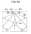
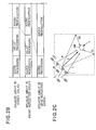
- FIG. 2 illustrates the state and the processing and propagation times of each sound beam output by a speaker array device.
- the AV system 1 is a 5ch surround system that includes two AV devices, i.e., a speaker array device 13 having both AV amplifier and speaker functions and a television device 11.
- the television device 11 receives a broadcast and a monitor 31 of the television device 11 displays an image of the broadcast and the speaker array device 13 emits a sound of the broadcast.
- a front left channel in the 5ch surround system is referred to as “Left (L) ch”
- a front right channel is referred to as “Right (R) ch”
- a center channel is referred to as “Center (C) ch”
- a rear left channel is referred to as “Surround Left (SL) ch”
- a rear right channel is referred to as “Surround Right (SR) ch”.
- the television device 11 corresponds to a video reproduction device and includes a receiver 21, a decoder 23, a signal input unit 25, an image processing unit 27, an image delay unit 29, a monitor (or display unit) 31, a sound processing unit 32, a sound delay unit 33, a D/A converter 34, a power amplifier 35, a speaker 36, a sound output unit 37, a communication unit 39, a storage unit 41, an operating unit 43, and a controller 45.
- the receiver 21 extracts a signal of a broadcast (content) of a frequency (physical channel) selected by a user from a radio wave received through an antenna 20 and outputs the extracted signal.
- the decoder 23 performs decoding, as signal processing, on the broadcast signal to extract a video signal and an audio signal. The decoder 23 then outputs the video signal to the image processing unit 27 and outputs the audio signal to the sound processing unit 32.
- the signal input unit 25 is an interface that receives an input of a video signal or an audio signal from the outside.
- the image processing unit 27 corresponds to an image processing unit and performs a variety of video signal processing (for example, video reproduction processing) such as signal processing associated with brightness and contrast adjustment and outputs a generated RGB video signal to the image delay unit 29.
- video signal processing for example, video reproduction processing
- the image delay unit 29 outputs the RGB video signal to the monitor 31 after delaying the output of the RGB video signal by a time indicated by the controller 45.
- the monitor (i.e., display unit) 31 corresponds to a display unit and displays an image based on the RGB video signal received from the image delay unit 29.
- the sound processing unit 32 corresponds to a first sound processing unit and performs audio signal processing (for example, audio reproduction processing) such as decompression of a compressed audio signal or impartment of audio effects to a sound emitted by the speaker 36 and outputs the resulting signal to the sound delay unit 33.
- audio signal processing for example, audio reproduction processing
- the sound delay unit 33 corresponds to a delay unit and outputs the audio signal to the speaker 36 and the sound output unit 37 after delaying the output of the audio signal by a time indicated by the controller 45.
- the D/A converter 34 converts the digital audio signal output from the sound delay unit 33 into an analog audio signal and outputs the analog audio signal.
- the power amplifier 35 amplifies and outputs the analog audio signal output from the D/A converter 34.
- the speaker 36 emits a sound based on the audio signal provided from the power amplifier 35.
- the sound output unit 37 is an interface for outputting the audio signal provided from the sound delay unit 33 from the television device 11.
- the communication unit 39 corresponds to a first communication unit and transmits and receives control information (such as information regarding the reproduction timing of content) to and from the speaker array device 13.
- the storage unit 41 stores information such as information of the time required for the television device 11 to perform image processing or sound processing.
- the operating unit 43 is a user interface that receives an operation performed by the user.
- the controller 45 controls each element of the television device 11 or performs calculation.
- the speaker array device 13 corresponds to an audio reproduction device and includes a signal input unit 51, a video sound processing unit 53, a signal output unit 54, a delay processing unit 57, D/A converters 61-1 to 61-N, power amplifiers 63-1 to 63-N, a speaker array 65 including speaker units 65-1 to 65-N, an A/D converter 67, an operating unit 69, a storage unit 71, a communication unit 73, and a controller 75.
- the signal input unit 51 is an interface that receives an input of an audio signal or a video signal from the outside.
- the signal input unit 51 outputs the input signal to the video sound processing unit 53.
- the video sound processing unit 53 corresponds to a second sound processing unit and performs processing, such as decoding or encoding or impartment of acoustic effects selected by the user, on the input audio signal and outputs the processed signal to the delay processing unit 57.
- the signal output unit 54 is an interface that outputs a video signal to an externally connected device.
- the delay processing unlit 57 delays the output of the audio signal by a time indicated by the controller 75 so that the image displayed on the monitor 31 is lip-synched with the sound output from the speaker array 65.
- the length of a path, along which each of a plurality of sound beams output from the speaker array 65 propagates until it arrives at a listening position L of the user, varies depending on the sound channel. For example, as shown in FIG. 2A , the path length of a sound beam of a center channel (Cch) is shortest since the sound beam arrives directly at (or propagates directly to) the listening position L. A sound beam of each of the front channels Lch and Rch arrives at the listening position L after being reflected at a wall of a room once. The path length of a sound beam of each of the rear channels SLch and SRch is longest since the sound beam arrives at the listening position L after being reflected at walls of the room twice.
- the delay processing unit 57 sets a delay time for each channel and adjusts the timings of output of the plurality of sound beams from the speaker array 65 so that the output sound beams arrive at the listening position at the same time.
- the delay processing unit 57 also corresponds to a beam control unit and distributes a sound to each channel (or each speaker unit) so that a plurality of sound beams is output through the speaker array 65, and adjusts the respective sound emission timings of the speaker units to output the plurality of sound beams.
- the delay processing unit 57 shortens the delay processing time increasingly in the same order so that the sound beam of each channel arrives at the listening position at the same time as shown in FIG. 2B .
- a preferred beam mode can be selected from a plurality of beam modes according to the arrangement of the speaker array 65 or a selection made by the user. For example, in the case where the speaker array 65 is installed at a corner of the room, the speaker array device 13 emits a sound beam of the center channel (Cch) and sound beams of the front channels (Lch and Rch) so that they arrive directly at the listening position L as shown in FIG. 2C . In addition, the speaker array device 13 emits sound beams of the rear channels (SLch and SRch) so that they arrive at the listening position L after being reflected at a wall of the room once.
- Cch center channel
- Lch and Rch sound beams of the front channels
- the number of reflections of a sound beam or the arrangement of the speaker array device 13 is different in each of the beam mode shown in FIG. 2A and the beam mode shown in FIG. 2C , and the path length of the sound beam is also different in each beam mode.
- the path length of a sound beam when another beam mode is selected in the speaker array device 13 is also different from those of the beam modes shown in FIG. 2A and FIG. 2C .
- the speaker array device 13 performs delay processing on a sound beam as described above. Accordingly, if the speaker array device 13 described above is connected to the television device 11 that is designed such that the internal sound output unit 37 outputs an audio signal so as to be lip-synced with an image displayed on the monitor 31, reproduction of the audio lags behind display of the image of the content, thereby causing a lack of lip-sync.
- the invention coincides the output timing of the image with the arrival timing of the sound beam to prevent the occurrence of a lack of lip-sync.
- a microphone 66 for receiving sounds is installed at the listening position of the user and the speaker array device 13 emits a test sound through the speaker array 65 and measures the distance between the speaker array 65 and the listening position or determines an optimal reflecting position of a sound beam of each channel using a known method.
- the speaker array device 13 also determines the emission timing of a sound beam of each channel based on information of the propagation distance or the sound propagation time of the sound beam of each channel.
- the sound propagation time is the length of time which elapses until the sound beam is received by the microphone after being emitted.
- the D/A converters 61-1 to 61-N convert digital audio signals output from the delay processing unit 57 into analog audio signals and output the analog audio signals.
- the power amplifiers 63-1 to 63-N amplify and output the analog audio signals output from the D/A converters 61-1 to 61-N.
- the speaker array 65 corresponds to a sound emission unit and includes speaker units 65-1 to 65-N that are disposed on a single panel in a predetermined array such as a matrix array, a line array, or a honeycomb array.
- the speaker units 65-1 to 65-N convert the audio signals amplified by the power amplifiers 63-1 to 63-N into sounds and emit the sounds.
- the A/D converter 67 converts a test analog sound received by the microphone 66 into a digital sound and outputs the digital sound to the controller 75.
- the operating unit 69 receives an operation such as a setting operation that the user performs on the speaker array device 13 and outputs a signal corresponding to the operation to the controller 45.
- the storage unit 71 stores a setting pattern or the like of the speaker units.
- the controller 75 reads data according to the operation received through the operating unit 69.
- the storage unit 71 also stores information of a time required for reproduction processing of sounds. That is, the storage unit 71 stores sound processing time information or reproduction processing time information such as information of the time required for the delay processing of a sound beam or information of the time during which the sound propagates to the listening position.
- the communication unit 73 corresponds to a second communication unit and transmits and receives control information to and from the television device 11.
- the controller 75 controls each element of the speaker array device 13 or performs calculation.
- the sound output unit 37 of the television device 11 is connected to the signal input unit 51 of the speaker array device 13 through a cable 12.
- the communication unit 39 of the television device 11 is connected to the communication unit 73 of the speaker array device 13 through a cable 14.
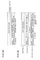
- FIGS. 3A to 3E are timing charts of video processing and audio processing in an AV system associated with the first embodiment of the invention.
- FIG. 3A is a timing chart of a conventional AV system and
- FIGS. 3B, 3C , 3D, and 3E are timing charts of the invention.
- the conventional television device delays the output of the audio signal from the internal audio output terminal so that the display of the image on the internal monitor coincides with (i.e., is lip-synced with) the output of the audio signal. Therefore, when acoustic effects are imparted to the audio signal through the AV amplifier or the speaker array device, there is a problem in that emission of the sound lags behind (i.e., is out of lip-sync with) display of the image by a time required to perform signal processing for imparting acoustic effects as shown in FIG. 3A .
- the speaker array device (AV amplifier) 13 notifies the counterpart (i.e., the device connected thereto) of information (such as the amount of delay) of a time required to process the audio signal (i.e., an audio processing time) or the television device 11 notifies the counterpart (i.e., the device connected thereto) of information (such as the amount of delay) of a time required to process the video signal (i.e., a video processing time) or of information (such as the amount of delay) of a time required to process the audio signal (i.e., an audio processing time) so as to adjust the delay time of the audio signal or the video signal in the television device 11.
- This enables the timing of display of the image on the monitor 31 of the television device 11 to coincide with the timing of arrival of a sound beam output from the speaker array 65 of the speaker array device 13 at the listening position.
- the speaker array device 13 adjusts the time for each sound to arrive at the listening position so that the sound beam of each channel simultaneously arrives at the listening position. Therefore, in the following description, it is assumed that the audio processing time of the speaker array device 13 includes the time required for the sound to arrive at the listening position (i.e., the sound propagation time).
- the AV system 1 is configured such that the speaker array device 13 notifies the television device 11 of information (such as the amount of delay) regarding a time required for the speaker array device 13 to process the audio signal.
- this information is set as a header command so that the speaker array device 13 notifies the television device 11 of the information through CEC of HDMI TM .
- the notification of such information may also be performed using a connection line such as RS-232C, through which information can be transmitted from the speaker array device 13 to the television device 11, without being limited to HDMI TM .
- the controller 45 of the television device 11 delays the timing of reproduction of the video by the difference between the sum of the sound processing times and the image processing time as shown in FIG. 3C .
- the processing time of the audio signal is generally shorter than the processing time of the video signal, the processing time of the audio signal is longer than the processing time of the video signal when the delay processing is performed so that a plurality of sound beams from the speaker array device simultaneously arrive at (or propagates to) the listening position L or when the game mode is selected at the television device 11.
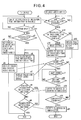
- FIG. 4 is a flow chart illustrating the processing operation of the AV system.
- the communication unit 39 of the television device 11 and the communication unit 73 of the speaker array device 13 are connected through CEC of HDMI TM .
- the controller 45 asks the speaker array device 13 whether or not the speaker array device 13 can provide the notification of audio signal processing time information through the communication unit (s1).
- the controller 75 of the speaker array device 13 waits until the ask is received from the television device 11 (s11: N). If the speaker array device 13 has no function to provide the notification of audio signal processing time information and thus cannot provide the notification, the controller 75 notifies the television device 11 of that fact (s13) when the ask has been received from the television device 11 (s11: Y). The controller 75 of the speaker array device 13 then waits until an audio signal is input to the speaker array device 13 (s16: N).
- the controller 45 of the television device 11 waits until an answer is received from the speaker array device 13 (s2: N).
- the controller 45 sets the timing of display of the image and the timing of output of the sound to coincide with each other if the speaker array device 13 has no function to provide notification of audio signal processing time information (s4).
- the controller 45 receives a broadcast signal of a channel selected by the user and outputs an audio signal of the broadcast signal to the speaker array device 13 and displays an image thereof on the monitor (s5).
- the controller 75 of the speaker array device 13 emits the sound (s17).
- the controller 75 of the speaker array device 13 performs the following procedure if the speaker array device 13 has the function to provide notification of audio signal processing time information and thus can provide the notification (s12: Y). That is, the controller 75 reads currently set processing time information of the audio signal from the storage unit 71 (s14). The controller 75 then notifies the television device 11 of both information indicating that the speaker array device 13 can provide notification of the audio signal processing time information and the processing time information of the audio signal through the communication unit 73 (s15).
- the controller 45 of the television device 11 performs the following procedure if an answer is received from the speaker array device 13 (s2: Y) and the speaker array device 13 has the function to provide notification of audio signal processing time information (s3: Y). That is, the controller 45 calculates reproduction processing time information so that the timing of display of the image at the television device 11 and the timing of arrival of the sound beam output from the speaker array device 13 at the listening position coincide with each other. The controller 45 then sets a delay time in the image delay unit 29 or the sound delay unit 33 (s6) (see FIGS. 3B and 3C ).
- the controller 45 of the television device 11 receives the broadcast signal of the channel selected by the user and outputs an audio signal of the broadcast signal to the speaker array device 13 and displays an image thereof on the monitor (s7).
- the controller 75 of the speaker array device 13 emits a sound (s16: Y) if the audio signal is input to the speaker array device 13 (s17).
- the controller 75 of the speaker array device 13 When the controller 75 of the speaker array device 13 has detected that the user has operated the operating unit 69 to change the setting of acoustic effects, the number of sound beams, or the listening position (s18: Y), the controller 75 notifies the television device 11 of a processing time change through this operation (s19).
- the controller 45 of the television device 11 When the controller 45 of the television device 11 has detected the notification of the change of the processing time from the speaker array device 13 (s8: Y), the controller 45 performs the process of step s6.
- the controller 75 of the speaker array device 13 When the controller 75 of the speaker array device 13 has detected that the user has operated the operating unit 69 to set the power to be off (i.e., the procedure to be terminated) (s20: Y), the controller 75 notifies the television device 11 of that fact (s21) and terminates the procedure.
- the controller 45 of the speaker array device 13 When the controller 45 of the speaker array device 13 has detected the notification of the setting of the procedure to be terminated from the speaker array device 13 (s9), the controller 45 terminates the procedure.
- the AV system 1 may also be configured such that the television device 11 notifies the speaker array device 13 of the time required for processing of the video signal and the time required for processing of the audio signal.
- the AV system 1 may also be configured such that the speaker array device 13 reads information such as EDID recorded in the storage unit 41 of the television device 11.
- the AV system 1 is configured such that the television device 11 outputs the audio signal without delaying the output of the audio signal and the speaker array device 13 delays the timing of output of the audio signal (see FIG. 3D ). That is, the AV system 1 performs processing for increasing the delay time of the audio signal at the speaker array device 13.
- transmission and reception of information such as EDID may be set to be performed through a header command of CEC of HDMI TM .
- the notification of such information may also be performed using a connection line such as RS-232C, through which information can be transmitted from the speaker array device 13 to the television device 11, without being limited to HDMI TM .
- the AV system 1 shown in FIG. 1 may also be configured such that an image of the content of a broadcast received by the television device 11 is displayed on the monitor 31 and a sound of the content is emitted through both the speaker 36 and the speaker array 65.
- this configuration is suitable for the case where a viewer A in a living room listens to a sound from the speaker 36 included in the television device 11 while viewing the monitor 31 and a viewer B in a kitchen adjacent to the living room listens to a sound (i.e., a beam sound) from the speaker array 65 installed in the living room.
- the AV system 1 When the AV system 1 has this configuration, there is a need to adjust the image displayed on the monitor 31 and the sound emitted from the speaker 36 so as to be lip-synced (i.e., synchronized) with each other.
- the viewer B hears not only the sound from the speaker array 65 but also the sound from the speaker 36. Therefore, it is necessary to synchronize the sound emitted from the speaker array 65 with the sound emitted from the speaker 36.
- the sound delay unit 33 of the television device 11 delays each of the audio signal, which is output to the D/A converter 34 to be emitted through the speaker 36, and the audio signal, which is output to the sound output unit 37, to synchronize each sound with the image as described above.
- the controller 45 of the television device 11 sets a delay time (i.e., the amount of delay) A in the sound delay unit 33 to allow the sound delay unit 33 to perform delay processing on the audio signal and output the delayed audio signal to the speaker 36 so that the speaker 36 emits the sound at the same time as when the monitor 31 displays the image.
- a delay time i.e., the amount of delay
- the controller 45 also sets a delay time (i.e., the amount of delay) B in the sound delay unit 33 to allow the sound delay unit 33 to perform delay processing on the audio signal and output the delayed audio signal through the sound output unit 37 so that the sound from the speaker array 65 and the sound from the speaker 36 are simultaneously heard at the listening position L of the viewer B, i.e., so that the speaker 36 and the speaker array 65 simultaneously emit the sounds.
- a delay time i.e., the amount of delay
- the AV system 1 may have a different configuration, without being limited to this configuration.
- the AV system 1 may also be configured such that a device such as a DVD player or a video reproduction device is connected to the signal input unit and image and audio signals of content reproduced by the device are input to the television device 11 through the signal input unit 25.
- the sound processing time of the speaker array device 13 (such as the time required for the video sound processing unit 53 or the delay processing unit 57 to process the audio signal or the time that elapses until the sound emitted from the speaker array 65 arrives at the listening position) varies according to the position of installation of the speaker array device 13 or the beam mode set in the speaker array device 13. Therefore, the speaker array device 13 is configured such that sound processing times according to beam modes are previously stored in the storage unit 71. The speaker array device 13 is also configured so as to transmit and receive information of the sound processing time according to the set beam mode to and from the television device 11. Accordingly, it is possible to reliably synchronize the image displayed on the monitor 31 of the television device 11 with the sound emitted from the speaker array 65 no matter which beam mode is set in the speaker array device 13.
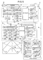
- FIG. 5 is a block diagram illustrating a schematic configuration of the AV system associated with the second embodiment of the invention.
- the AV system 2 includes a television device 11, a speaker array device 13, and a DVD player (source device) 15.
- the AV system 2 associated with the second embodiment is different from that of the first embodiment in that content is transmitted from the DVD player 15 to the television device 11 and the speaker array device 13.
- the DVD player 15 includes a DVD reproduction unit 81, a decoder 83, a video signal output unit 85, an audio signal output unit 87, a communication unit 89, a controller 91, a storage unit 93, and an operating unit 95.
- the DVD reproduction unit 81 reads an information signal of content stored in a DVD and outputs the information signal to the decoder 83.
- the decoder 83 decodes the information signal of the content to extract a video signal and an audio signal.
- the decoder 83 outputs the video signal to the video signal output unit 85 and outputs the audio signal to the audio signal output unit 87.
- the video signal output unit 85 is an interface that outputs the video signal provided from the decoder 83 from the DVD player 15.
- the audio signal output unit 87 is an interface that outputs the audio signal provided from the decoder 83 from the DVD player 15.
- the communication unit 89 can transmit and receive control information to and from another device.
- the controller 91 controls each element of the DVD player 15.
- the storage unit 93 stores information such as information of the time required for the DVD player 15 to perform image processing.
- the operating unit 95 receives an operation that the user has performed on the DVD player 15.
- the video signal output unit 85 of the DVD player 15 is connected to the signal input unit 25 of the television device 11 through a cable 16.
- the audio signal output unit 87 of the DVD player 15 is connected to the signal input unit 51 of the speaker array device 13 through a cable 17.
- the communication unit 39 of the television device 11 is connected to the communication unit 73 of the speaker array device 13 through a cable 14.
- a video signal of content of a DVD reproduced by the DVD player 15 is output to the television device 11 and an audio signal of the content is output to the speaker array device 13.
- the communication unit 39 of the television device 11 and the communication unit 73 of the speaker array device 13 transmit and receive processing time information of the television device 11 and processing time information of the speaker array device 13 through the cable 14.
- the speaker array device 13 calculates the difference between the processing times of the two signals and delays the timing of output of the video signal by a time corresponding to the difference. Through this procedure, it is possible to prevent the occurrence of a lack of lip-sync even when content is reproduced through the DVD player 15.
- the two methods may be appropriately switched when used for an actual system.
- the method of the second embodiment may be used to achieve lip-sync when the speaker array device 13 receives content from a source device and the method of the first embodiment may be used to achieve lip-sync when the speaker array device 13 receives content from a device other than the source device such as a TV device.
- the television device 11 and the speaker array device 13 may not only be set to be in an equivalent relationship but may also be set to be in a master-slave relationship. Specifically, the following procedure is performed in the AV system 2 shown in FIG. 5 when the television device 11 is set as a master and the speaker array device 13 is set as a slave.
- the controller 45 of the television device 11 reads processing time information of an audio signal recorded in the storage unit 71 of the speaker array device 13.
- the controller 45 then reads processing time information of a video signal from the storage unit 41.
- the controller 45 calculates the difference between the processing times of the two signals.
- the controller 45 instructs the speaker array device 13 to delay the timing of output of the audio signal by a time corresponding to the difference.
- the controller 45 calculates the difference between the processing times of the two signals and causes the image delay unit 29 to delay the timing of output of the video signal by a time corresponding to the difference.
- the AV system 2 shown in FIG. 5 may be set to perform a procedure in which the processes of the television device 11 and the speaker array device 13 are exchanged in the above procedure when the speaker array device 13 is set as a master and the television device 11 is set as a slave.
- FIG. 6 is a block diagram illustrating a schematic configuration of an AV system associated with a third embodiment of the invention.
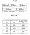
- FIG. 7 is a timing chart of image processing and sound processing in the AV system.
- the AV system 3 associated with the third embodiment of the invention is different from those of the first and second embodiments in that content is transmitted from a DVD player 15' to a television device 11 through a speaker array device 13'.
- the television device 11 has the same configuration as shown in FIGS. 1 and 5 .
- the speaker array device 13' is only partially different from the speaker array device 13 shown in FIG. 5 .
- the DVD player 15' is also only partially different from the DVD player 15 shown in FIG. 5 .
- the speaker array device 13' is configured by replacing the signal input unit 51 in the speaker array device 13 with a signal input unit 51'. While only the audio signal is input to the signal input unit 51 in the speaker array device 13 shown in FIGS. 1 and 5 , both the image and audio signals are input to the signal input unit 51' shown in FIG. 6 .
- the DVD player 15' is configured by replacing the video signal output unit 85 and the audio signal output unit 87 in the DVD player 15 with a audio/video signal output unit 86.
- the audio/video signal output unit 86 is an interface that outputs sound and video signals provided from the decoder 83 from the DVD player 15'.
- the audio/video signal output unit 86 of the DVD player 15' which is a source device, is connected to the signal input unit 51' of the speaker array device 13', which is a repeater device, through a cable 18-1.
- a communication unit 89 of the DVD player 15' is connected to a communication unit 73 of the speaker array device 13' through a cable 18-2.
- a signal output unit 54 of the speaker array device 13' which is a repeater device, is connected to a signal input unit 25 of the television device 11, which is a sink device, through a cable 14-1.
- the communication unit 73 of the speaker array device 13' is connected to a communication unit 39 of the television device 11 through a cable 14-2.
- the AV system 3 is configured such that a source device, one or more repeater devices, and a sink device are connected in series and each device outputs a signal to a downstream device.
- AV amplifier not only the AV amplifier or the speaker array device but also a signal switching device may be used as the repeater device.
- the two cables are actually a single HDMI TM cable 14 and the cable 18-1 and the cable 18-2 are also a single HDMI TM cable 18.
- each device may report the processing time of a video signal and the processing time of an audio signal in the device or the difference between the processing times of the two signals to another connected device.
- the processing time of the video signal is longer than the processing time of the audio signal.
- the processing time of the audio signal is longer than the processing time of the video signal in the entirety of the AV system 3.
- one of the component devices of the AV system 3 serves as a master and performs communication with other connected devices through a communication unit and acquires, from each connected device, the processing time of the video signal and the processing time of the audio signal in the device or the difference between the processing times of the two signals.
- a controller in the master device calculates the difference between the entire video signal processing time and the entire audio signal processing time of the AV system 3.
- the AV system 3 may be configured such that one device performs delay processing of the video signal or the audio signal according to the capacity of a buffer memory for delay processing of each device.
- the buffer memory capacity of the entire system is significant in the case where a buffer memory with capacity required to enable adjustment for eliminating the difference is installed in each device as in the conventional television device.
- the difference between the processing times of image and audio signals in the entirety of the AV system 3 is obtained and one device collectively performs delay processing. Therefore, it is possible to reduce the entire buffer memory capacity of the system. That is, it is possible to perform adjustment for eliminating the difference of the entire system even though the capacity of a buffer memory installed in each device is reduced.
- the AV system 3 is set to ignore the amount of delay of one of the devices subsequent to (i.e., downstream of) a device that outputs the signal early. For example, the amount of sound delay of the television device 11 is ignored and assumed to be 0 seconds when the speaker array device 13' emits the sound and the television device 11 displays the image in the case where the AV system 3 is configured such that signals flow through the devices in the order of the DVD player 15' (source device) -> the speaker array device 13' (repeater device) -> the television device 11 (sink device) as described above.
- the AV system 3 shown in FIG. 6 may also be configured such that each device notifies the master device of information of the maximum time (i.e., the maximum amount of delay or the buffer memory capacity), by which the device can delay the video signal and the audio signal, through a communication unit and, based on this information, the master device notifies each device of the amount of delay allocated to the device through a communication unit.
- the master device notifies the master device of information of the maximum time (i.e., the maximum amount of delay or the buffer memory capacity), by which the device can delay the video signal and the audio signal, through a communication unit and, based on this information, the master device notifies each device of the amount of delay allocated to the device through a communication unit.
- one device which is set as a master, can divide the entire signal delay of the AV system 3 among the devices according to the capacity of the buffer memory of each device since it is possible to determine a delay time, by which each device can perform delay processing.
- the difference between the times required to process the image and audio signals in terms of the entirety of the AV system in such a manner it is possible not only to reduce the difference but also to distribute the difference to the devices, thereby reducing the required capacity of a buffer memory in each device.
- the AV system illustrated in FIG. 6 is configured such that the devices are connected in series in the order of the DVD player 15' (source device) -> the speaker array device 13' (repeater device) -> the television device 11 (sink device), the AV system may have a different configuration, without being limited to this configuration.
- a source device such as a DVD player or a video reproduction device may be connected to the signal input unit 25 of the television device 11.
- the television device 11 serves as a repeater device and the speaker array device 13 serves as a sink device.
- a switching device may be connected to the signal input unit 51 and a plurality of source devices may be connected to the switching device.
- the plurality of source devices preferably includes a DVD player, a disc game console, and a hard disc recorder. When the devices are connected in this manner, two repeater devices are connected between the source device and the sink device.
- the time required to process the video signal or the audio signal or the difference between the processing times of the two signals varies according to image or sound settings such as the resolution of the image displayed on the monitor 31 of the television device 11 or the mode of sound field processing.
- the processing time of the video signal varies according to the image correction processing, such as contour emphasis, scaling, progressive conversion (IP conversion), game mode, image resolution, or the like.
- the processing time of the audio signal varies according to the length of the path of the sound beam, the sound beam mode, the DSP mode, the (compressed or uncompressed) sound format, or the like.
- the path length of the center channel is short since the sound beam of the center channel arrives directly at the listening position L as described above.
- the path lengths of the rear channels SLch and SRch are long since the sound beams of the rear channels arrive at the listening position L after being reflected at walls of the room twice.
- the path length also varies according to the size of the room in which the speaker array device 13' is installed, there is a need to store the amount of delay (such as the processing time of the audio signal) according to the size of the room or to calculate and store the amount of delay (such as the processing time of the audio signal) in the storage unit when the device is installed.
- the invention stores the processing time of the video signal or the audio signal according to an image or sound setting (mode) selected by the user.
- the television device 11 or the speaker array device 13' stores the processing time (i.e., the amount of delay) of the video signal or the audio signal according to the resolution of image, the mode of sound field processing, or the like in a table format as shown in FIG. 8 in the storage unit.
- FIG. 8 illustrates a table for managing the processing time of the video signal or the audio signal according to image resolution, sound field processing mode, or the like.
- the processing time i.e., the amount of delay
- FIG. 8 is an example illustrated for ease of explanation.
- the processing time (i.e., the amount of delay) of the video signal in the television device 11 is 5msec in the case where the input resolution is 480i and the output resolution is 480i.
- the processing time (i.e., the amount of delay) of the video signal is 90msec when the input resolution is 480i and the output resolution is 1080i.
- the processing time (i.e., the amount of delay) of the audio signal in the speaker array device 13' is 40msec when acoustic effects of a sports mode are selected as acoustic effects imparted to the audio signal.
- the processing time (i.e., the amount of delay) of the audio signal is 60msec when acoustic effects of a concert hall mode are selected.
- the processing time (i.e., the amount of delay) of the audio signal is 15msec when the format of the audio signal is AAC and the processing time (i.e., the amount of delay) of the audio signal is 20msec when the format of the audio signal is MP3.
- the video signal processing time varies according to the image resolution and the audio signal processing time varies according to the sound field program or the sound format as described above. Accordingly, there is a need to change the amount of delay according to the selected resolution, sound field program, or the like.
- the processing time of the audio signal or the video signal may be managed in the following manner in the case where the processing time of the audio signal or the video signal is managed using a header command of HDMI TM .
- processing time information of the audio signal or the video signal may be stored in EDID.
- delay amount information or information indicating that the amount of delay has been changed may be transferred using one of HDMI TM Info Frame, HDMI TM CEC, or DDC.
- the processing time i.e., the amount of delay
- the invention is not limited to this configuration and may employ a different configuration.
- a test disc on which test data is recorded so that the image and the sound are simultaneously output, or a test signal generator is used as a source
- a light receiving sensor is installed on the TV screen
- a microphone for sound reception i.e., the microphone 66
- the amounts of delay of the two signals or the difference between the amounts of delay is measured using the timings of change (or trigger) of the two signals and the above setting is then performed based on the measurement.
- the invention is not limited to this example and one or more speakers connected to an AV amplifier may, of course, be used instead of the speaker array device.
- FIG. 9 illustrates a schematic configuration of a conventional AV system and a relation between processing times.
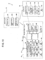
- FIG. 10 is a block diagram illustrating a schematic configuration of an AV system associated with the fourth embodiment of the invention.
- FIG. 11 illustrates a relation between processing times in the AV system associated with the fourth embodiment of the invention.
- the AV system 4 shown in FIG. 9A includes a music player 10, which is an audio reproduction device (i.e., a source device), a speaker array device 13, which is a first AV device, and a subwoofer 19, which is a second AV device.
- the music player 10 broadcasts an audio signal of the content to the speaker array device 13 and the subwoofer 19.
- Each of the speaker array device 13 and the subwoofer 19 reproduces a sound of the content.
- the conventional AV system 4 does not have a configuration in which information of a time required to reproduce the content is transmitted from the speaker array device 13 to the subwoofer 19 or a configuration wherein the subwoofer 19 delays the sound.
- the time required for the subwoofer 19 to perform audio reproduction processing is short (or small), compared to that of the speaker array device 13, and the subwoofer 19 does not perform a process requiring time such as DSP processing.
- the sound processing time of the speaker array device 13 is significantly longer than that of the subwoofer 19 since sound beams output from the speaker array device 13 propagate to (or arrive at) the listening position of the listener at the same time directly or after being reflected once or twice depending on the channels as described above. Therefore, bass sounds emitted by the subwoofer 19 arrive at the listening position earlier than sounds (i.e., sound beams) emitted by the speaker array device 13 as shown in FIG. 9B .
- a speaker array device 13 includes a component (i.e., a communication unit 73) that transmits, to a subwoofer 19, information of a time required for reproduction processing of content, i.e., information (reproduction processing time information) such as information of a time that elapses until the sound of the content arrives at the listening position or information of a time required for delay processing of the sound beam.
- a component i.e., a communication unit 73
- information reproduction processing time information
- the subwoofer 19 includes a component (i.e., a communication unit 111) that receives reproduction processing time information transmitted by the speaker array device 13 and a delay circuit that delays a sound emitted from the speaker based on the reproduction processing time information received from the speaker array device 13.
- a component i.e., a communication unit 111 that receives reproduction processing time information transmitted by the speaker array device 13 and a delay circuit that delays a sound emitted from the speaker based on the reproduction processing time information received from the speaker array device 13.
- the AV system 4' can delay a sound emitted from the subwoofer 19 so that the sound emitted from the subwoofer 19 and a sound beam emitted from the speaker array device 13 which is an AV device having a latest reproduction timing as shown in FIG. 11 are synchronized with each other, i.e., simultaneously arrive at the listening position. Accordingly, the AV system 4' can emit surround sound without causing the listener to feel uncomfortable.
- the reproduction processing time required for the subwoofer 19 is always shorter than that of the speaker array device 13.
- the subwoofer 19, which is an AV device requiring a short time for reproduction processing only needs to have a configuration for receiving information indicating delay of reproduction of content from the speaker array device 13 which is another AV device and then delaying the reproduction of the content. This eliminates the need to adjust content reproduction timing with that of another AV device, thereby simplifying the configuration.
- reproduction processing time information is transmitted and received between the AV devices and an AV device requiring a short time for reproduction processing is determined based on the information during initial setting. Then, the AV device requiring a short time for reproduction processing is configured so as to receive reproduction processing time information from other AV devices and to delay reproduction of content based on the received information.
- the music player 10 includes a storage unit 101, a reproduction unit 103, and a communication unit 105.
- the speaker array device 13 has the same configuration as shown in FIG. 1 .
- the subwoofer 19 includes a communication unit 111, a bass sound generator 113, a delay circuit 115, an amplifier 117, and a speaker 119.
- the reproduction unit 103 reads and reproduces data (sound data of two channels) of content from the storage unit 101.
- the communication unit 105 superimposes the reproduced audio signal on a radio wave and transmits the resulting signal through broadcasting.
- the video sound processing unit 53 performs sound processing (specifically, DSP processing) for expanding the audio signals of the two channels to audio signals of five channels (i.e., surround audio signals).
- the delay processing unit 57 performs delay processing on audio signals of other channels in accordance with a channel which arrives at the listening position last.
- the speaker array device 13 transmits reproduction processing time information to the subwoofer 19 through the communication unit 73.
- the speaker array device 13 generates respective sound beams of the channels by performing, through the delay processing unit 57, predetermined delay processing based on reproduction processing time information so that the sound beams of the channels propagate to positions around the listening position and then outputs the sound beams through the speaker array 65.
- the bass sound generator 113 adds the audio signals of the two channels to extract only a bass signal. Then, the delay circuit 115 delays the bass signal based on the reproduction processing time information transmitted from the speaker array device 13, the amplifier 117 amplifies the delayed bass signal, and the speaker 119 then outputs the amplified bass signal.
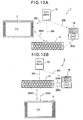
- FIGS. 12 and 13 are conceptual diagrams illustrating other AV system configurations according to the invention.
- an AV system 5 includes a DVD player 15', which is a source device, a speaker array device 13-1, a speaker array device 13-2, and a subwoofer 19. Descriptions of the configurations of the devices shown in FIGS. 12 and 13 are omitted since they are mostly the same as those shown in FIGS. 1 , 5 , 6 , and 10 .
- each device shown in FIGS. 12 and 13 includes a communication unit that transmits and receives an audio signal or reproduction processing time information through broadcasting.
- the DVD player 15' broadcasts audio signals 201 of 7.1 channels to the speaker array device 13-1, the speaker array device 13-2, and the subwoofer 19. Sound beams of 7 channels are generated through the two speaker array devices 13-1 and 13-2.
- the speaker array device 13-1 is configured to generate sound beams of Cch, Lch, and Rch
- the speaker array device 13-2 is configured to generate sound beams of SLch, SRch, BLch, and BRch.
- the speaker array device 13-1 and the speaker array device 13-2 transmit and receive their own reproduction processing time information 203A to and from each other and perform delay processing on other sound beams in accordance with a sound beam that arrives at the listening position last.
- One of the speaker array device 13-1 and the speaker array device 13-2 serves as a master and transmits reproduction processing time information 205A to the subwoofer 19.
- the speaker array device 13-1 transmits the reproduction processing time information 205A.
- the speaker array devices may be replaced with AV amplifier devices as shown in FIG. 12B .
- the AV amplifier devices may transmit and receive their own reproduction processing time information 203B or reproduction processing time information 205B to and from each other and perform delay processing on other sound beams in accordance with a sound beam that arrives at the listening position last.
- the AV system may also be configured such that a plurality of audio reproduction devices and a video reproduction device transmit and receive delay processing information as shown in FIG. 13A .
- the AV system 7 shown in FIG. 13A includes a subwoofer 19 in addition to the components of the AV system 2 described above.
- the devices also transmit and receive their own reproduction processing time information 203C or reproduction processing time information 205C to and from each other, perform delay processing on other sound beams in accordance with a sound beam that arrives at the listening position last, and a television device 11 displays the image at the timing of arrival of the sound at the listening position. This allows the user who is located at the listening position to feel that video and audio are synchronized (i.e., lip-synced) with each other.
- the subwoofer 19 may be configured so as to switch the delay time (i.e., the amount of delay) according to a signal 202B from the speaker array device 13 (i.e., a repeat signal received via another AV device) or a signal 202 that is transmitted from the source device (i.e., the DVD player 15) through broadcasting (i.e., a signal received directly from the source device).
- the speaker array device 13 determines a device, from which the subwoofer 19 is set to receive signals, and transmits corresponding reproduction processing time information 205D to the subwoofer 19.
- the television device 11 displays the image at the timing of arrival of the sound at the listening position. Accordingly, video and audio are synchronized in the entirety of the system, thereby allowing the user who is located at the listening position to feel that video and audio are synchronized (i.e., lip-synced) with each other.
- the AV system may also be configured such that the controller 75 of the speaker array device 13, which corresponds to a sound emission control unit, outputs a sound emission start (i.e., mute release) and sound emission termination (i.e., mute) command to the subwoofer 19, which is an AV device requiring a short time for reproduction processing, to control the timing of start of sound emission and the subwoofer 19 switches operations according to this signal.
- a sound emission start i.e., mute release
- sound emission termination i.e., mute
- the speaker array device 13 Since the speaker array device 13 performs DSP processing or delay processing as described above, the time that elapses until it emits a sound is longer than that of the subwoofer 19. Especially, the activation time that elapses until the speaker array device 13 emits a sound after power is turned on is longer than that of the subwoofer 19 and the subwoofer 19 is activated before the speaker array device 13 transmits reproduction processing time information to the subwoofer 19. Therefore, the subwoofer 19 alone previously emits a bass sound. Accordingly, the speaker array device 13 outputs a sound emission start (i.e., mute release) and sound emission termination (i.e., mute) command to the subwoofer 19 and the subwoofer 19 switches operations according to this signal.
- a sound emission start i.e., mute release
- sound emission termination i.e., mute
- the AV system may also be configured such that the speaker array device 13 outputs a volume setting command to the subwoofer 19 and the subwoofer 19 switches operations according to this signal.
- the subwoofer 19 determines that the volume setting command indicates mute release.
- This configuration prevents the subwoofer 19 from previously emitting a bass sound, thereby allowing the speaker array device 13 and the subwoofer 19 to simultaneously emit sounds.
Landscapes
- Engineering & Computer Science (AREA)
- Signal Processing (AREA)
- Multimedia (AREA)
- Physics & Mathematics (AREA)
- Acoustics & Sound (AREA)
- Stereophonic System (AREA)
- Television Receiver Circuits (AREA)
- Two-Way Televisions, Distribution Of Moving Picture Or The Like (AREA)
- Studio Circuits (AREA)
Applications Claiming Priority (2)
| Application Number | Priority Date | Filing Date | Title |
|---|---|---|---|
| JP2008135349 | 2008-05-23 | ||
| JP2009096891A JP5316189B2 (ja) | 2008-05-23 | 2009-04-13 | Avシステム |
Publications (2)
| Publication Number | Publication Date |
|---|---|
| EP2136576A2 true EP2136576A2 (fr) | 2009-12-23 |
| EP2136576A3 EP2136576A3 (fr) | 2013-07-03 |
Family
ID=41264071
Family Applications (1)
| Application Number | Title | Priority Date | Filing Date |
|---|---|---|---|
| EP09006885.9A Withdrawn EP2136576A3 (fr) | 2008-05-23 | 2009-05-22 | Système AV |
Country Status (3)
| Country | Link |
|---|---|
| US (1) | US20090290064A1 (fr) |
| EP (1) | EP2136576A3 (fr) |
| JP (1) | JP5316189B2 (fr) |
Cited By (1)
| Publication number | Priority date | Publication date | Assignee | Title |
|---|---|---|---|---|
| EP2955713A1 (fr) * | 2014-06-12 | 2015-12-16 | Huawei Technologies Co., Ltd. | Procédé, appareil et système de lecture audio synchrone |
Families Citing this family (35)
| Publication number | Priority date | Publication date | Assignee | Title |
|---|---|---|---|---|
| JPH0777921B2 (ja) | 1991-09-25 | 1995-08-23 | 日本碍子株式会社 | 容器搬送用コンベヤ |
| EP1805918B1 (fr) | 2004-09-27 | 2019-02-20 | Nielsen Media Research, Inc. | Procedes et appareil d'utilisation d'information d'emplacement pour gerer un debordement dans un systeme de surveillance d'audience |
| JP4912296B2 (ja) * | 2005-04-28 | 2012-04-11 | パナソニック株式会社 | リップシンク補正システム、リップシンク補正装置及びリップシンク補正方法 |
| US8274611B2 (en) * | 2008-06-27 | 2012-09-25 | Mitsubishi Electric Visual Solutions America, Inc. | System and methods for television with integrated sound projection system |
| US8279357B2 (en) * | 2008-09-02 | 2012-10-02 | Mitsubishi Electric Visual Solutions America, Inc. | System and methods for television with integrated sound projection system |
| CN102461212B (zh) * | 2009-06-05 | 2015-04-15 | 皇家飞利浦电子股份有限公司 | 环绕声系统及用于其的方法 |
| JP5427617B2 (ja) | 2010-01-13 | 2014-02-26 | 日立オムロンターミナルソリューションズ株式会社 | 紙幣収納庫および紙幣取扱装置 |
| US8855101B2 (en) * | 2010-03-09 | 2014-10-07 | The Nielsen Company (Us), Llc | Methods, systems, and apparatus to synchronize actions of audio source monitors |
| JP5454248B2 (ja) * | 2010-03-12 | 2014-03-26 | ソニー株式会社 | 送信装置、および送信方法 |
| JP5677470B2 (ja) | 2011-02-03 | 2015-02-25 | パナソニックIpマネジメント株式会社 | 音声読上げ装置、音声出力装置、音声出力システム、音声読上げ方法および音声出力方法 |
| US8913104B2 (en) * | 2011-05-24 | 2014-12-16 | Bose Corporation | Audio synchronization for two dimensional and three dimensional video signals |
| EP2533547A1 (fr) * | 2011-06-10 | 2012-12-12 | Koninklijke KPN N.V. | Procédé et système pour fournir une expérience d'utilisateur synchronisée à partir de plusieurs modules |
| JP5284451B2 (ja) * | 2011-11-30 | 2013-09-11 | 株式会社東芝 | 電子機器及び音声出力方法 |
| JP5957760B2 (ja) * | 2012-03-08 | 2016-07-27 | パナソニックIpマネジメント株式会社 | 映像音声処理装置 |
| WO2013146602A1 (fr) * | 2012-03-26 | 2013-10-03 | ヤマハ株式会社 | Amplificateur av |
| TWI496455B (zh) * | 2013-04-10 | 2015-08-11 | Wistron Corp | 影音同步檢測裝置與方法 |
| KR102170827B1 (ko) * | 2013-11-22 | 2020-10-28 | 삼성전자주식회사 | 영상표시장치 및 영상표시장치의 구동방법, 음향출력장치 및 음향출력장치의 구동방법 |
| KR102201617B1 (ko) * | 2014-01-07 | 2021-01-12 | 삼성전자 주식회사 | Av기기 및 그 제어방법 |
| JP2015171065A (ja) * | 2014-03-10 | 2015-09-28 | 富士通株式会社 | システムおよび方法 |
| WO2015174753A1 (fr) | 2014-05-16 | 2015-11-19 | Samsung Electronics Co., Ltd. | Appareil de sortie de contenu, appareil mobile, et leurs procédés de commande |
| US9762999B1 (en) * | 2014-09-30 | 2017-09-12 | Apple Inc. | Modal based architecture for controlling the directivity of loudspeaker arrays |
| KR102342081B1 (ko) * | 2015-04-22 | 2021-12-23 | 삼성디스플레이 주식회사 | 멀티미디어 장치 및 이의 구동 방법 |
| US9848222B2 (en) | 2015-07-15 | 2017-12-19 | The Nielsen Company (Us), Llc | Methods and apparatus to detect spillover |
| JP2017163432A (ja) * | 2016-03-10 | 2017-09-14 | ソニー株式会社 | 情報処理装置、情報処理方法、及び、プログラム |
| CN105812902B (zh) * | 2016-03-17 | 2018-09-04 | 联发科技(新加坡)私人有限公司 | 数据播放的方法、设备及系统 |
| JP6311784B2 (ja) * | 2016-12-20 | 2018-04-18 | ソニー株式会社 | テレビジョン受像機、音声処理方法、音声処理プログラム、オーディオ機器、音声出力方法および音声出力プログラム |
| US10531196B2 (en) * | 2017-06-02 | 2020-01-07 | Apple Inc. | Spatially ducking audio produced through a beamforming loudspeaker array |
| CN108616767B (zh) * | 2018-04-28 | 2020-12-29 | 海信视像科技股份有限公司 | 一种音频数据传输方法及装置 |
| KR102527842B1 (ko) * | 2018-10-12 | 2023-05-03 | 삼성전자주식회사 | 전자 장치 및 그 제어 방법 |
| KR102650734B1 (ko) * | 2019-04-17 | 2024-03-22 | 엘지전자 주식회사 | 복수의 스피커들에 다채널 오디오 신호를 제공하기 위한 오디오 장치, 오디오 시스템 및 방법 |
| JP7412091B2 (ja) * | 2019-05-08 | 2024-01-12 | 株式会社ディーアンドエムホールディングス | オーディオ装置およびオーディオシステム |
| JP7412090B2 (ja) * | 2019-05-08 | 2024-01-12 | 株式会社ディーアンドエムホールディングス | オーディオシステム |
| FR3105686A1 (fr) * | 2019-12-18 | 2021-06-25 | Sagemcom Broadband Sas | Equipement décodeur à double liaison audio |
| US12407890B2 (en) * | 2021-02-26 | 2025-09-02 | Ad Connected, Inc. | Method of synchronizing playback of video and audio of digital content and device using the same |
| CN115904303A (zh) * | 2021-05-21 | 2023-04-04 | 荣耀终端有限公司 | 一种播放声音的方法及设备 |
Citations (2)
| Publication number | Priority date | Publication date | Assignee | Title |
|---|---|---|---|---|
| JP2006033436A (ja) | 2004-07-16 | 2006-02-02 | Sony Corp | 映像音声処理システム、アンプ装置および音声遅延処置方法 |
| WO2006118106A1 (fr) * | 2005-04-28 | 2006-11-09 | Matsushita Electric Industrial Co., Ltd. | Dispositif de correction lip-sync et méthode de correction lip-sync |
Family Cites Families (14)
| Publication number | Priority date | Publication date | Assignee | Title |
|---|---|---|---|---|
| GB0000874D0 (en) * | 2000-01-14 | 2000-03-08 | Koninkl Philips Electronics Nv | Latency handling for interconnected devices |
| JP2001345751A (ja) * | 2000-06-05 | 2001-12-14 | Sharp Corp | 無線通信システム及びこの無線通信システムにおける送信装置及び受信装置 |
| WO2002078388A2 (fr) * | 2001-03-27 | 2002-10-03 | 1... Limited | Procede et appareil permettant de creer un champ acoustique |
| EP1398931B1 (fr) * | 2002-09-06 | 2006-05-03 | Sony Deutschland GmbH | Emission synchrone des paquets media |
| JP2004193868A (ja) * | 2002-12-10 | 2004-07-08 | Alps Electric Co Ltd | 無線送受信システム及び無線送受信方法 |
| JP2005051660A (ja) * | 2003-07-31 | 2005-02-24 | Onkyo Corp | 映像信号および音声信号の再生システム |
| JP2005136464A (ja) * | 2003-10-28 | 2005-05-26 | Pioneer Electronic Corp | データ出力装置、データ送信装置、データ処理システム、データ出力方法、データ送信方法、データ処理方法、それらのプログラム、および、それらのプログラムを記録した記録媒体 |
| JP4150750B2 (ja) * | 2004-03-24 | 2008-09-17 | パイオニア株式会社 | 音声出力装置、音声信号出力調整方法、及び音声信号出力調整処理プログラム等 |
| JP4127248B2 (ja) * | 2004-06-23 | 2008-07-30 | ヤマハ株式会社 | スピーカアレイ装置及びスピーカアレイ装置の音声ビーム設定方法 |
| US7636126B2 (en) * | 2005-06-22 | 2009-12-22 | Sony Computer Entertainment Inc. | Delay matching in audio/video systems |
| JP4184397B2 (ja) * | 2005-11-11 | 2008-11-19 | シャープ株式会社 | 映像音声処理システムおよびその制御方法、音声処理システム、映像音声処理システム制御プログラム、ならびに該プログラムを記録した記録媒体 |
| JP2008060675A (ja) * | 2006-08-29 | 2008-03-13 | Sony Corp | 音声再生装置、音声再生方法 |
| JP4362734B2 (ja) * | 2006-09-22 | 2009-11-11 | セイコーエプソン株式会社 | 同期再生システム |
| JP4516156B2 (ja) * | 2008-02-06 | 2010-08-04 | パナソニック株式会社 | 映像音声データ同期方法、映像出力機器、音声出力機器及び映像音声出力システム |
-
2009
- 2009-04-13 JP JP2009096891A patent/JP5316189B2/ja not_active Expired - Fee Related
- 2009-05-21 US US12/470,177 patent/US20090290064A1/en not_active Abandoned
- 2009-05-22 EP EP09006885.9A patent/EP2136576A3/fr not_active Withdrawn
Patent Citations (3)
| Publication number | Priority date | Publication date | Assignee | Title |
|---|---|---|---|---|
| JP2006033436A (ja) | 2004-07-16 | 2006-02-02 | Sony Corp | 映像音声処理システム、アンプ装置および音声遅延処置方法 |
| WO2006118106A1 (fr) * | 2005-04-28 | 2006-11-09 | Matsushita Electric Industrial Co., Ltd. | Dispositif de correction lip-sync et méthode de correction lip-sync |
| US20090073316A1 (en) * | 2005-04-28 | 2009-03-19 | Naoki Ejima | Lip-sync correcting device and lip-sync correcting method |
Cited By (3)
| Publication number | Priority date | Publication date | Assignee | Title |
|---|---|---|---|---|
| EP2955713A1 (fr) * | 2014-06-12 | 2015-12-16 | Huawei Technologies Co., Ltd. | Procédé, appareil et système de lecture audio synchrone |
| KR20150142596A (ko) * | 2014-06-12 | 2015-12-22 | 후아웨이 테크놀러지 컴퍼니 리미티드 | 동기 오디오 재생 방법, 장치 및 시스템 |
| US10180981B2 (en) | 2014-06-12 | 2019-01-15 | Huawei Technologies Co., Ltd. | Synchronous audio playback method, apparatus and system |
Also Published As
| Publication number | Publication date |
|---|---|
| JP5316189B2 (ja) | 2013-10-16 |
| JP2010004520A (ja) | 2010-01-07 |
| EP2136576A3 (fr) | 2013-07-03 |
| US20090290064A1 (en) | 2009-11-26 |
Similar Documents
| Publication | Publication Date | Title |
|---|---|---|
| EP2136576A2 (fr) | Système AV | |
| US20050025318A1 (en) | Reproduction system for video and audio signals | |
| US7277551B2 (en) | Sound reproducing apparatus and sound reproducing method | |
| KR20100049836A (ko) | 화면음원 정위장치, 화면음원 정위를 위한 스피커 셋 정보 생성방법 및 정위된 화면음원 재생방법 | |
| KR20070098448A (ko) | Av 장치 및 이의 제어 방법 | |
| JP2004260281A (ja) | 音響制御システム、音響制御装置、電子機器及び音響制御方法 | |
| JP5590186B2 (ja) | Avシステム | |
| JP2009260458A (ja) | 音響再生装置、および、これを含む映像音声視聴システム | |
| JP4830644B2 (ja) | コントロール機器、同期補正方法および同期補正プログラム | |
| WO2010122802A1 (fr) | Appareil de reproduction sonore | |
| JP6720566B2 (ja) | オーディオ機器 | |
| JP2012227647A (ja) | マルチチャンネル音響による空間音響再生システム | |
| EP3179739B1 (fr) | Dispositif de traitement audio | |
| EP2178308A2 (fr) | Dispositif de traitement de signal audio et procédé de traitement de signal audio | |
| KR20080079428A (ko) | 홈시어터의 음량조절 시스템 및 그의 동작방법 | |
| KR101634387B1 (ko) | 멀티 채널 오디오 재생 장치 및 시스템 | |
| JP4816307B2 (ja) | オーディオシステム | |
| JP5067240B2 (ja) | 遅延制御装置 | |
| WO2013146602A1 (fr) | Amplificateur av | |
| CN108028986A (zh) | 控制终端、音频系统以及控制音频系统的方法 | |
| JP2014096735A (ja) | 音声処理装置 | |
| JP6074899B2 (ja) | 音データ処理装置 | |
| KR100793790B1 (ko) | 무선 비디오 시스템 및 이 무선 비디오 시스템에서 신호를처리하는 방법 | |
| KR100917713B1 (ko) | 비디오매트릭스장치와 이를 구비하는 전관방송시스템 | |
| KR101403682B1 (ko) | 오디오 데이터를 전송하는 영상기기 및 그의 오디오 데이터전송방법 |
Legal Events
| Date | Code | Title | Description |
|---|---|---|---|
| PUAI | Public reference made under article 153(3) epc to a published international application that has entered the european phase |
Free format text: ORIGINAL CODE: 0009012 |
|
| AK | Designated contracting states |
Kind code of ref document: A2 Designated state(s): AT BE BG CH CY CZ DE DK EE ES FI FR GB GR HR HU IE IS IT LI LT LU LV MC MK MT NL NO PL PT RO SE SI SK TR |
|
| PUAL | Search report despatched |
Free format text: ORIGINAL CODE: 0009013 |
|
| AK | Designated contracting states |
Kind code of ref document: A3 Designated state(s): AT BE BG CH CY CZ DE DK EE ES FI FR GB GR HR HU IE IS IT LI LT LU LV MC MK MT NL NO PL PT RO SE SI SK TR |
|
| AX | Request for extension of the european patent |
Extension state: AL BA RS |
|
| RIC1 | Information provided on ipc code assigned before grant |
Ipc: H04S 3/00 20060101AFI20130524BHEP Ipc: H04N 5/04 20060101ALI20130524BHEP |
|
| 17P | Request for examination filed |
Effective date: 20140103 |
|
| RBV | Designated contracting states (corrected) |
Designated state(s): AT BE BG CH CY CZ DE DK EE ES FI FR GB GR HR HU IE IS IT LI LT LU LV MC MK MT NL NO PL PT RO SE SI SK TR |
|
| 17Q | First examination report despatched |
Effective date: 20180222 |
|
| STAA | Information on the status of an ep patent application or granted ep patent |
Free format text: STATUS: THE APPLICATION IS DEEMED TO BE WITHDRAWN |
|
| 18D | Application deemed to be withdrawn |
Effective date: 20180705 |