EP2136584A2 - Station de base sans fil, terminal mobile, procédé de contrôle de communication, et système de communication sans fil - Google Patents
Station de base sans fil, terminal mobile, procédé de contrôle de communication, et système de communication sans fil Download PDFInfo
- Publication number
- EP2136584A2 EP2136584A2 EP09162615A EP09162615A EP2136584A2 EP 2136584 A2 EP2136584 A2 EP 2136584A2 EP 09162615 A EP09162615 A EP 09162615A EP 09162615 A EP09162615 A EP 09162615A EP 2136584 A2 EP2136584 A2 EP 2136584A2
- Authority
- EP
- European Patent Office
- Prior art keywords
- mobile terminals
- signal
- base station
- wireless base
- connection
- Prior art date
- Legal status (The legal status is an assumption and is not a legal conclusion. Google has not performed a legal analysis and makes no representation as to the accuracy of the status listed.)
- Withdrawn
Links
Images


Classifications
-
- H—ELECTRICITY
- H04—ELECTRIC COMMUNICATION TECHNIQUE
- H04W—WIRELESS COMMUNICATION NETWORKS
- H04W28/00—Network traffic management; Network resource management
- H04W28/02—Traffic management, e.g. flow control or congestion control
-
- H—ELECTRICITY
- H04—ELECTRIC COMMUNICATION TECHNIQUE
- H04W—WIRELESS COMMUNICATION NETWORKS
- H04W74/00—Wireless channel access
- H04W74/002—Transmission of channel access control information
-
- H—ELECTRICITY
- H04—ELECTRIC COMMUNICATION TECHNIQUE
- H04W—WIRELESS COMMUNICATION NETWORKS
- H04W74/00—Wireless channel access
- H04W74/08—Non-scheduled access, e.g. ALOHA
- H04W74/0833—Random access procedures, e.g. with 4-step access
Definitions
- the embodiments discussed herein are related to a wireless base station, a mobile terminal, a communications controlling method, and a wireless communications system.
- Random Access Channel is provided as one of the channels which realize communications between user equipment [UE (for example, a mobile terminal)] and a wireless base station (for example, e-Node B (eNB)).
- This RACH is a wireless channel shared with other UE belonging to the same cell (or sector) of an eNB, and is used, for example, when UE starts communications with the eNB.
- the UE selects one of the 64 kinds of RACH preamble codes (RACH number), and transmits an RACH preamble notification (Message 1) including the RACH number toward the eNB. Then, upon reception of the Message 1, a series of connection sequence is started.
- RACH preamble code RACH preamble code
- Message 1 RACH preamble notification
- these Messages 1 can collide with one another. Since it is impossible for the eNB to normally receive the colliding Messages 1 so that the multiple UE which have transmitted the Message 1 is incapable of normally completing a connection sequence with the eNB, it can occur that the multiple pieces of UE repeat retransmission of the Message 1.
- a congestion state can be caused in a communications network.
- an apparatus includes a wireless base station which is capable of communicating with a plurality of mobile terminals, the wireless base station including: a monitor that monitors a ratio of the number of connection sequences which are started upon reception of connection request signals transmitted from the mobile terminals to the number of connection sequences which are completed; and an evaluator that evaluates the presence or the absence of a congestion state based on the monitoring result obtained by the monitor.
- an apparatus includes a mobile terminal which is capable of communicating with a wireless base station, the mobile terminal including: a transmitter that transmits a connection request signal toward the wireless base station; and a controller that restricts new transmission processing performed by the transmitter according to information indicating restriction of the transmission, which information is received upon decision of an occurrence of a congestion condition by monitoring a ratio of the number of connection sequences which are started upon reception of a connection request signal transmitted from the mobile terminals to the number of connection sequences which are completed.
- a method includes a communication controlling method for use in a wireless communications system, including: a plurality of mobile terminals; a wireless base station which is capable of communicating with the plurality of mobile terminals, the communications controlling method including: on the wireless base station, monitoring a ratio of the number of connection sequences which are started upon reception of a connection request signal transmitted from the mobile terminals to the number of connection sequences which are completed; and evaluating whether a congestion condition is present or absent, based on the monitoring result.
- a system includes a wireless communications system, including: a plurality of mobile terminals; a wireless base station which is capable of communicating with the plurality of mobile terminals; a monitor that monitors a ratio of the number of connection sequences which are started upon reception of a connection request signal from the mobile terminals to the number of connection sequences which are completed; an evaluator that evaluates whether a congestion condition is present or absent, based on the monitoring result obtained by the monitor; a mobile terminal controller that restricts transmission of a new connection request signals from the mobile terminals when the evaluator decides that the congestion condition occurs; a transmitter that transmits a connection request signal toward the wireless base station; and a controller that restricts new transmission processing performed by the transmitter according to information indicating the restriction of the transmission, which information is received from the wireless base station.
- the communications direction from the communications network 300 to the eNB 100 and the communications direction from the eNB 100 to the UE 200 are called “downlink”; the communications direction from the UE 200 to the eNB 100 and the communications direction from the eNB 100 to the communications network 300 are called “uplink”.
- the eNB 100 is, for example, capable of relaying data and calls between the communications network 300 and the UE 200 and also controlling communications; the UE 200 is capable of transceiving data and calls therebetween.
- FIG. 2 illustrates an example of a case where a connection sequence with RACH is normally completed.
- the UE 200 selects the RACH number at random from the RACH number table which the local station 200 has, and then transmits an RACH preamble notification (Message 1) (hereinafter, will be called "M1 signal") including this RACH number toward the eNB 100.
- Message 1 hereinafter, will be called "M1 signal”
- the eNB 100 which has received an M1 signal from the UE 200 selects a temporary number (Cell-Radio Network Temporary Identity: C-RNTI) for recognizing the UE 200 from the intra-cell management number table which the local station 100 has. Then, the local station 100 transmits back the RACH preamble response (Message 2) (hereinafter, will be described as the "M2 signal"), including the RACH number, the temporary number, and transmission timing information, toward the UE 200. Further, the eNB 100 is also capable of assigning uplink communications resources for used in communications thereafter to the UE 200.
- C-RNTI Cell-Radio Network Temporary Identity
- the UE 200 transmits a terminal-unique ID notification (Message 3) (hereinafter, will be described as the "M3 signal") to the eNB 100 at transmission timing calculated from the M2 signal using communications recourses given from the eNB 100.
- This M3 signal includes, for example: the temporary number assigned to the eNB 100 and the identification data unique to the UE 200 (terminal-unique ID).
- the eNB 100 which has received the M3 signal confirms (evaluates) whether or not the UE 200 that has transmitted the M3 signal is a communications subject based on the temporary number, the terminal-unique ID, and a communications terminal management control table.
- the eNB 100 evaluates whether or not the terminal-unique ID received from the UE 200 matches the terminal-unique ID of a communications subject managed on the host communications network end, thereby being capable of evaluating whether or not the terminal-unique ID is valid.
- the eNB 100 transmits a communications reception notification (Message 4) (hereinafter, will be described as the "M4 signal"), including information for use in call control or the like, to the UE 200.
- M4 signal a communications reception notification
- the UE 200 which has received the M4 signal confirms that the local station 200 is a communications subject, and obtains information relating to call controlling, and then starts communications with the eNB 100.
- connection sequence with RACH is normally completed.
- the UE 200 performs predetermined control with respect to calls with the eNB 100 by use of information relating to call control.
- the M1 signal is transmitted with the same RACH number and at the same timing.
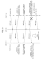
- FIG. 3 illustrates an example of a connection sequence with RACH in such a case.
- RACH number #N
- N is a natural number
- the eNB 100 transmits the same M2 signals toward both of the UE 200-1 and 200-2.
- These same M2 signals include, for example: the same RACH number; the temporary number, and the transmission timing information.
- each of the UE 200-1 and 200-2 which has received the same M2 signal, separately transmits the temporary number and the M3 signal containing the terminal-unique ID of the local station toward the eNB 100.
- the eNB 100 which has received the M3 signals from the UE 200-1 and the UE 200-2 confirms (evaluates) whether or not each of the UE 200-1 and 200-2 is valid as a communications subject.
- the eNB 100 transmits the M4 signal, which indicates that the UE 200-1 is a valid communications subject, toward the UE 200-1 and the UE 200-2, respectively.
- the UE 200-1 confirms that the local UE 200-1 is a valid communications subject based on the above mentioned information contained in the M4 signal received from the eNB 100 and then starts communications (call controlling or the like) with the eNB 100.
- the UE 200-2 confirms that the local station 200-2 is not a valid communications subject, based on information contained in the M4 signal. In this case, the UE 200-2 repeats retransmission of the M1 signal until the above connection sequence is normally completed (until the local station is confirmed to be a valid communications subject). Further, as exemplified in FIG. 4 , when more than one piece of UE 200 transmits more than one M1 signal with the same RACH number (#N) at the same timing, these M1 signals mutually interference with each other, so that none of the M1 signals cannot be normally received by the eNB 100.
- the UE 200-1 and the UE 200-2 is incapable of receiving the M2 signal within a predetermined time duration, so that the UE 200-1 and the UE 200-2 retransmit the M1 signal. It can occur that this retransmission processing is repeated, for example, until the M2 signal is received from the eNB 100 within the predetermined time duration.
- this retransmission processing is repeated, for example, until the M2 signal is received from the eNB 100 within the predetermined time duration.
- the eNB 100 monitors the ratio of the number of connection sequences started upon reception of the M1 signal to the number of connection sequences having been normally completed. On the basis of the monitoring result, the eNB 100 evaluates the presence or the absence of a congestion state in the communications network.
- the eNB 100 is capable of restricting transmission of the M1 signal by the UE 200 when deciding that the communications network is in a congestion state.
- the eNB 100 is also capable of evaluating the presence or the absence of a congestion state in the communications network and also restricting transmission of the UE 200 based on a difference between the number of received M1 signals and the number of transmitted M4 signals. Further, when deciding that the congestion state in the communications network is resolved, the eNB 100 is capable of lifting the transmission restriction.
- FIG. 5 is a block diagram illustrating a construction example of the eNB 100 according to one preferred embodiment.
- the eNB 100 exemplified in FIG. 5 includes: a transceiving antenna 101; a wireless processing part 102; an interface (IF) 103; and a call controller 104.
- the uplink wireless signal from the UE 200 received by the reception function of the transceiver antenna 101 is subjected to predetermined wireless reception processing performed by the wireless processing part 102, and is then transmitted to the communications network 300 through the IF 103.
- the downlink signal received from the communications network 300 is subjected to a predetermined wireless transmission processing performed by the wireless processing part 102, and is then transmitted toward the UE 200 with the transmission function of the transceiver antenna 101.
- the call controller 104 for example, manages and controls call connection with the UE 200.
- the wireless processing part 102 includes, for example: a downlink signal processing part 105 and an uplink signal processing part 106.
- the downlink signal processing part 105 which performs predetermined wireless transmission processing on a downlink signal, has, for example, a data CH processing part 107 and a control CH processing part 108.
- the data CH processing part 107 performs predetermined wireless transmission processing on downlink data
- the control CH processing part 108 performs predetermined wireless transmission processing on a downlink control CH.
- the control CH processing part 108 in the present example is capable of broadcasting a predetermined data signal toward the UE 200 by a broadcast CH under control performed by a difference calculator/congestion detector 115, which control will be detailed later.
- the uplink signal processing part 106 which performs predetermined wireless reception processing on an uplink signal, includes, for example: a RACH processing part 109; a control CH processing part 110; and a data CH processing part 111.
- the control CH processing part 110 performs predetermined wireless reception processing on the control CH of an uplink signal;
- the data CH processing part 111 performs predetermined wireless reception processing on the data CH of an uplink signal.
- the RACH processing part 109 performs predetermined wireless processing on the RACH of the uplink signal.
- the RACH processing part 109 includes: a power calculator 112; a Message 1 reception processing part/Message 2 transmission processing part 117; a Message 3 reception processing part/Message 4 transmission processing part 119; and a timer 120. Further, the RACH processing part 109 further includes: an adder 113; memories 114 and 118; an intra-cell management number table 122; a communications terminal management control table 123; a difference calculator/congestion detector 115; and a threshold value table 121.
- the Message 1 reception processing part/Message 2 transmission processing part 117 will be simply called the “M1/M2 transceiving processing part 117"
- the Message 3 reception processing part/Message 4 transmission processing part 119 is simply called the "M3/M4 transceiving processing part 119”.
- the M1/M2 transceiving processing part 117 calculates the number of M1 signals received from the UE 200 as value 2, based on the number of M2 signals transmitted to the UE 200.
- the M1/M2 transceiving processing part 117 is incapable of calculating the number of received M1 signals for the collision thereof. For example, even when the eNB 100 receives two or more M1 signals, the number of transmitted M2 signals (the number of received M1 signals) is "1".
- the number of received M1 signals calculated by the M1/M2 transceiving processing part 117 does not include the number of M1 signals colliding with one another.
- the number of above described signals colliding with one another is calculated separately by the power calculator 112.
- the M1/M2 transceiving processing part 117 according to the present example is also capable of performing normal processing relating to the connection sequence with RACH.
- the M1/M2 transceiving processing part 117 extracts the RACH number contained in the M1 signal and then transmits the M2 signal containing the thus extracted RACH number and the M2 signal containing the temporary number and the transmission timing information relating to the M3 signal, which are selected from the intra-cell management table 122, toward the UE 200.
- the intra-cell management number table 122 stores therein temporary numbers (C-RNTI) identifying each UE 200 in a cell. Further, the temporary number selected by the M1/M2 transceiving processing part 117, for example, can be notified to the communications terminal management control table 123 and stored therein.
- the power calculator 112 calculates the number of M1 signals colliding with one another, based on the reception power value of the transceiver antenna 101.
- the power calculator 112 is capable of detecting that the n-number of M1 signals have collided with one another in a case, for example, where the reception power value at the transceiver antenna 101 is approximately n ( n is a natural number) times as large as the already known reception power value in a case where no collision is present. Further, according to the present example, when detecting that the n-number of M1 signals have collided with one another, the power calculator 112 calculates and outputs (n - 1) as a correction value (Value 1) for the collision thereamong.
- the adder 113 adds the Value 2 calculated by the M1/M2 transceiving processing part 117 and the Value 1 calculated by the power calculator 112 together, and then outputs the thus obtained result to the memory 114.
- the memory 114 which is a storage device dedicated to the eNB 100 or a shared one, holds therein the thus obtained addition result (the number of received M1 signals in consideration of the number of colliding ones).
- the M3/M4 transceiving processing part 119 calculates the number of transmitted M4 signals (connection permission signal) as Value 3.
- the M3/M4 transceiving processing part 119 is also capable of performing normal processing relating to the connection sequence with RACH. For example, after evaluation as to whether or not the UE 200 is a subject communications terminal by comparing the temporary number and the terminal-unique ID contained in the M3 signal and the contents in the communications terminal management control table 123, when a confirmation is made as to if the UE 200 is a subject communications terminal, an M4 signal containing information indicating the thus obtained confirmation result is transmitted to the UE 200.
- the communications terminal management control table 123 stores therein the temporary number notified from the intra-cell management number table 122 and the terminal-unique ID from the UE 200 in association with each other.
- the memory 118 which is a storage device dedicated to the eNBs 100 or a shared one, holds therein the Value 3 (the number of transmitted M4 signals) calculated by the M3/M4 transceiving processing part 119.
- the difference calculator/congestion detector 115 calculates a difference between the number of received M1 signals (Value 2 + Value 1) held in the memory 114 and the number of transmitted M4 signals (Value 3) held in the memory 118.
- the difference calculator/congestion detector 115 evaluates whether or not the communications network is in a congestion state based on, for example, the above mentioned difference calculation result. Then, when deciding that the communications network is in a congestion state, the difference calculator/congestion detector 115 broadcasts a transmission restriction signal to the UE 200, thereby restricting the transmission processing of the UE 200.
- the condition for use in the evaluation of the congestion state need only to be that which expresses a normal completion ratio of the above connection sequence, and the condition is not limited to a difference between the number of received M1 signals and the number of transmitted M4 signals.
- the difference calculator/congestion detector 115 functions as an example of a monitor which monitors a ratio of the number of connection sequences started upon reception of the M1 signal (connection request signal) transmitted from the UE 200 to the number of connection sequences having been completed. Further, the difference calculator/congestion detector 115 functions as an example of the evaluators which evaluate the presence or the absence of a congestion state in the communications network based on the thus obtained monitoring result.
- the threshold value table 121 stores therein more than one item of threshold value information [the first threshold value (Th1), the second threshold value (Th2), the third threshold value (Th3), and threshold value X] used in evaluation performed by the difference calculator/congestion detector 115.
- Th1, Th2, Th3, and X are natural numbers, and Th1, Th2, and Th3 satisfy a relationship of Th3 ⁇ Th1 ⁇ Th2.
- the difference calculator/congestion detector 115 decides that the communications network is in a congestion state in a case, for example, where the value obtained by subtracting the number of transmittedM4 signals from the number of received M1 signals is equal to or larger than the first threshold value (Th1). Then, the difference calculator/congestion detector 115 according to the present example broadcasts a signal (restriction instruction signal) to halt the new RACH connection sequences for a new part thereof toward each UE 200 through the control CH processing part 108.
- the difference calculator/congestion detector 115 and the control CH processing part 108 functions as an example of a mobile terminal controller which restricts transmission of a new M1 signal by the UE 200 when it is evaluated that a congestion state occurs. Further, the difference calculator/congestion detector 115 decides that the communications in the communications network is in a more serious congestion state in a case, for example, where the value obtained by subtracting the number of transmitted M4 signals from the number of received M1 signals is equal to or larger than the second threshold value (Th2) larger than the above mentioned Th1.
- Th2 second threshold value
- the difference calculator/congestion detector 115 broadcasts a signal (information relating to threshold value X) for restricting transmission of the M1 signal according to the number of times of retransmission toward each UE 200 by way of the control CH processing part 108.
- the UE 200 that has received this broadcasted signal restricts transmission of the M1 signal based on information relating to the number of times of retransmission of the M1 signal of the local station 200 and information relating to the above mentioned threshold X.
- transmission of the M1 signal is restricted (halted) with respect to the UE 200 with the number of times of retransmission of the M1 signal, which number is equal to or smaller than the threshold value X.
- the eNB 100 broadcasts a signal (restriction lifting signal) for lifting the above mentioned restriction of the M1 signal toward each UE 200 by way of, for example, the control CH processing part 108. This makes it possible to lift the transmission restriction when the congestion state in the communications network is resolved.
- the timer 120 resets the calculation results of the power calculator 112, the M1/M2 transceiving processing part 117, and the M3/M4 transceiving processing part 119 at a predetermined monitoring time interval set by a user (a network manager or the like). This makes it possible to evaluate the congestion state of the communications network by the unit of predetermined monitoring time duration, so that it becomes also possible to perform communication control suitable for the current state of the communications network.
- the time duration required from reception of an M1 signal by the eNB 100 to transmission of the corresponding M4 signal is approximately 24 msec through several hundreds msec, and its average is often approximately 100 msec.
- the monitoring time of the timer 120 is set to 80 msec.
- the value to be set as the monitoring time of the timer 120 is not limited to this value, and it is possible for a user or the like to appropriately change the value.
- the eNB 100 monitors a ratio of the number of connection sequences started upon reception of an M1 signal to the number of connection sequences having been completed (for example, a difference between the number of received M1 signals and the number of transmitted M4 signals), and evaluates the presence or the absence of a congestion state based on the thus obtained monitoring result.
- This makes it possible for the eNB 100 to evaluate the congestion state of the communications network based on signals transceived in the connection sequence with RACH, so that early detection of the congestion state becomes available.
- transmission processing of an M1 signal which processing is performed by the UE 200, makes it possible to early restrict the occurring congestion.
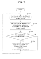
- the power calculator 112 calculates reception power value at the time of receiving an RACH signal by the transceiver antenna 101 (step S101), and then calculates the number of M1 signals that have collided with one another from the thus calculated reception power value (step S102). For example the power calculator 112 of the present example calculates approximately how many times larger is the reception power value at the transceiver antenna 101 than the already known reception power in a case where no collision occurs. On the basis of the calculation result, the number of received M1 signals collided with one another is capable of being calculated.
- the power calculator 112 evaluates whether or not the number of M1 signals which have collided with one another is larger than a value of "1" (step S103).
- the number of M1 signals which have collided with one another is added to the Value 1 (step S104).
- the number of M1 signals which have collided with one another is equal to or smaller than a value of 1 (No route of step S103)
- the power calculator 112 repeats the processing from the above steps S101 through S104, thereby collecting information relating to the number of M1 signals which have collided with one another.
- the value of the above Value 1 can be reset by the timer 120 at each elapse of the predetermined monitoring time duration.
- the power calculator 112 calculates the number of received M1 signals that have collided with one another, which number is incapable of being calculated by the M1/M2 transceiving processing part 117, and corrects the number of received M1 signals calculated by the M1/M2 transceiving processing part 117.
- the processing exemplified in FIG. 8 is performed on the M1 signal which is normally received.
- the timer 120 starts measuring of the predetermined monitoring time (step S105), and the M1/M2 transceiving processing part 117 receives an M1 signal from the UE 200 through the transceiver antenna 101 (step S106).
- the M1/M2 transceiving processing part 117 selects a temporary number (C-RNTI) from the intra-cell management number table 122, and then transmits an M2 signal including the received RACH number, the thus selected temporary number, and the transmission timing information, toward the UE 200 (step S107).
- the M1/M2 transceiving processing part 117 substitutes the sum of the number of transmitted M2 signals and the Value 1 calculated by the power calculator 112, as the accurate number of received M1 signals, into the value 2 (step S108). This makes it possible for the eNB 100 to count the number of received M1 signals in consideration of the number of M1 signals which have collided with one another.
- the M3/M4 transceiving processing part 119 receives an M3 signal, including the temporary number and the terminal-unique ID, from the UE 200 (step S109).
- the M3/M4 transceiving processing part 119 confirms if the UE 200 is a communications subject (whether or not the received terminal-unique ID is valid) based on the temporary number and the terminal-unique ID included in the M3 signal and the communications terminal management control table 123.
- theM3/M4transceiving processing part 119 transmits information indicating as such and an M4 signal, including information for use in call controlling or the like, to the UE 200 (step S110).
- the M3/M4 transceiving processing part 119 adds the number of transmitted M4 signals to the Value 3 (step S111). This makes it possible to count the number of connection sequences which have been normally completed, out of the connection sequences started upon reception of an M1 signal.
- the eNB 100 evaluates whether or not the above predetermined monitoring time duration, which is set by the timer 120, has elapsed (step S112).
- the timer 120 decided that the above mentioned monitoring time duration has elapsed (Yes route of step S112)
- the values of the Value 1 through the Value 3 are deleted (reset) (step S119), and the processing proceeds to the previous stage to the step S105 (see the reference character A in FIG. 8 ).
- This makes it possible to evaluate a congestion state in the communications network every when the predetermined monitoring time duration elapses, so that congestion state evaluation controlling suitable for the current state of the communications network becomes possible to be performed.
- the eNB 100 evaluates whether or not transmission restriction of an M1 signal has already been performed to the UE 200 (step S113).
- the difference calculator/congestion detector 115 evaluates whether or not the value (sequence completion ratio) obtained as a result of the calculation of the number of received M1 signals (Value 2) - the number of transmitted M4 signals (value 3) is equal to or larger than Th1 (step S114).
- step S114 when the eNB 100 decides that the formula, Value 2 - Value 3 ⁇ Th1, does not hold (No route of step S114), the processing proceeds to the stage previous to the step S106 (see the reference character B in FIG. 8 ), and monitoring of the completion ratio of the connection sequence is continued.
- the formula, Value 2 - Value 3 ⁇ Th1 holds (Yes route of step S114), it is decided that the communications network is in a congestion state, and further, it is evaluated whether or not the value obtained as a result of the calculation, Value 2 - Value 3, is equal to or larger than Th2 which is larger than Th1 (step S115).
- a restriction instruction signal is broadcasted toward each UE 200 with the downlink broadcasting CH for the purpose of halting new transmission processing of the M1 signal of the UE 200 (step S118).
- the eNB 100 makes the processing proceed to the stage previous to the step S106 (see the reference character B in FIG. 8 ), and continues monitoring of the completion ratio of the connection sequence, and performs the above communications controlling. Further, when deciding that the formula, Value 2 - Value 3 ⁇ Th2 (Yes route of the step S115), holds, the eNB 100 decides that the communications network is in a serious congestion state, and restricts the transmission processing of the M1 signal also with respect to the UE 200 on which retransmission of the M1 signal is performed the X-number of times or less.
- the difference calculator/congestion detector 115 determines the threshold value X according to the value obtained by the calculation, Value 2 - Value 3 (step S116), and then broadcasts information relating to the threshold value X toward each UE 200 by use of the downlink broadcast CH (step S117). At that time, for example, if X is enlarged in a stepwise fashion as the value obtained by the calculation, Value 2 - Value 3, becomes larger, it is possible to relieve the UE 200 on which the number of times of retransmission performed is large, and it is also possible to restrict (halt) transmission processing performed by the UE 200 on which retransmission is performed the X-number of times or less.
- the term of "relieve” means "permit transmission of the UE 200 in which the number of times of retransmission is large".
- the eNB 100 decides that it is in the above transmission restriction state (Yes route of the step S113), it is evaluated if the formula of Value 2 - Value 3 ⁇ Th3 holds (step S120).
- the eNB 100 decides that the congestion state of the communications network is relieved. Then, the eNB 100 broadcasts a restriction lift signal to each UE 200 with the downlink broadcast CH (step S121).
- the eNB 100 when deciding that the formula, Value 2 - Value 3 ⁇ Th3, does not hold (No route of the step S120), the eNB 100 makes the processing proceed to the stage previous to the step S106 (see the reference character B in FIG. 8 ), and continues monitoring of the completion ratio of the connection sequence, and performs the above communications controlling. In this manner, according to the present example, the eNB 100 monitors a ratio of the number of connection sequences started upon reception of the M1 signal transmitted from each UE 200 to the number of completed connection sequences calculated based on transmission of the M4 signal, and evaluates the presence or the absence of a congestion state based on this monitoring result.
- FIG. 6 is a block diagram illustrating an example of a construction of UE 200 according to one preferred embodiment.
- the UE 200 depicted in FIG. 6 includes: a transceiver antenna 201; a wireless processing part 202; and a call controller 203.
- the downlink radio signal from the eNB 100 received by the reception function of the transceiver antenna 201 is subjected to predetermined wireless reception processing performed by the wireless processing part 202.
- the uplink wireless signal from the UE 200 is subjected to predetermined wireless transmission processing performed by the wireless processing part 202, and is then transmitted out toward the eNB 100 with the transmission function of the transceiver antenna 201.
- the call controller 203 manages and controls call connection with the eNB 100, for example.
- the wireless processing part 202 include, for example, a downlink signal processing part 204 and an uplink signal processing part 205.
- the downlink signal processing part 204 which performs predetermined wireless reception processing on a downlink signal, includes, for example, a data CH processing part 206 and a control CH processing part 207.
- the data CH processing part 206 performs predetermined wireless reception processing on the data CH of a downlink signal;
- the control CH processing part 207 performs predetermined wireless reception processing on the control CH of a downlink signal.
- the control CH processing part 207 according to the present example is also capable of performing reception processing to a broadcast CH signal from the eNB 100.
- this broadcasting CH signal includes, for example, any one of the control instruction signal, the information relating to the threshold value X, and the restriction lift signal.
- the uplink signal processing part 205 which performs predetermined wireless reception processing on an uplink signal, includes, for example: a RACH processing part 208; a control CH processing part 209; and a data CH processing part 210.
- the control CH processing part 209 performs predetermined wireless transmission processing on the control CH of an uplink signal; the data CH processing part 210 performs predetermined wireless transmission processing on the data CH of an uplink signal.
- the RACH processing part 208 performs predetermined wireless processing on RACH of the uplink signal. From this reason, the RACH processing part 208 according to the present example includes, for example: a Message 1 transmission processing part 211; a RACH preamble code table 212; and a Message 2 reception processing part 213. Further, the RACH processing part 208 includes, for example: a Message 3 transmission processing part 214; a Message 4 reception processing part 215; a RACH controller 216; and a timer 217.
- the Message 1 transmission processing part (transmitter) 211 selects a single RACH number from the RACH preamble code table 212, and generates an M1 signal including the thus selected RACH number, and then transmits the thus generated M1 signal toward the eNB 100.
- the above selection is capable of employing a predetermined selection reference such as using random numbers.
- the RACH preamble code table 212 stores therein more than one RACH number. According to the present example, for example, 64 kinds of RACH numbers are stored in the RACH preamble code table 212.
- the Message 2 reception processing part 213 performs reception processing on the Message 2 according to the present example extracts, for example, the RACH number, the temporary number, the transmission timing information, and so on, from an M2 signal, and then notifies the RACH controller 216 of the thus extracted information items.
- the Message 3 transmission processing part 214 generates an M3 signal and then transmits the thus generated M3 signal to the eNB 100.
- the M3 signal including the temporary number notified from the eNB 100 and the identification information (terminal-unique ID) unique to each UE 200.
- the Message 4 reception processing part 215 performs reception processing on an M4 signal received from the eNB 100 through the transceiver antenna 201. In a case, for example, where the Message 4 reception processing part 215 confirms that the local station 200 is a communications subject, the Message 4 reception processing part 215 notifies the RACH controller 216 of as such. Further, information which is included in the M4 signal and is used in communications (call controlling or the like) performed thereafter is notified to the call controller 203 by way of the RACH controller 216.
- the RACH controller 216 controls the above mentioned connection sequence with RACH on the UE 200.
- the RACH controller 216 controls the Message 1 transmission processing part 211 to generate and transmit an M1 signal and starts the connection sequence.
- the RACH controller 216 controls the Message 3 transmission processing part 214 to generate and transmit an M3 signal based on the contents (RACH number, temporary number, transmission timing information, and so on) of the M2 signal notified from the Message 2 reception processing part 213. Further, in a case, for example, where the RACH controller 216 according to the present example confirms that the local station 200 is a communications subject due to an M4 signal, the RACH controller 216 notifies the call controller 203 of information for use in call controlling or the like.
- the timer 217 measures the time elapsing from transmission of the M1 signal or the M3 signal to reception of the M2 signal or the M4 signal, and then notifies the RACH controller 216 of the measurement result. This makes it possible for the RACH controller 216 according to the present example to perform retransmission processing of the M1 signal or the M3 signal when the M2 signal or the M4 signal is not received even when a predetermined time duration elapses from transmission of the M1 signal or the M3 signal.
- the RACH controller 216 counts the number of times of retransmission of the M1 signal or the M3 signal, and then notifies the call controller 203 of the thus obtained counting result. In this instance, the counting result can be reset upon reception of the M2 signal or the M4 signal as a trigger thereof.
- the call controller (controller) 203 controls the RACH controller 216 based on the contents of a broadcast CH signal from the eNB 100, thereby controlling the connection sequence with RACH.
- the UE 200 when receiving a restriction instruction signal for restricting new sequence processing, out of the connection sequence with RACH, from the eNB 100, the UE 200 is capable of controlling the Message 1 transmission processing part 211 to restrict (halt) new transmission of the M1 signal. This makes it possible for the UE 200 to suppress an occurring congestion state, since the eNB 100 is capable of restricting the transmission processing of the M1 signal, when the eNB 100 decides that the communications network is in a congestion state.
- the UE 200 controls the Message 1 transmission processing part 211 to restrict (halt) transmission of the M1 signal which is transmitted the number of times equal to or smaller than the threshold value X. Further, when receiving a signal (restriction lift signal) for lifting the above restriction from the eNB 100, for example, the UE 200 controls the Message 1 transmission processing part 211 to start (restart) transmission of the M1 signal, that is, the connection sequence with RACH.
- control CH processing part 207 performs reception processing on the broadcast CH signal from the eNB 100 (step S201), and the call controller 203 recognizes the kind of broadcasting CH signal from the eNB 100 (step S202).
- the call controller 203 controls the RACH controller 216 and the Message 1 transmission processing part 211 to restrict (halt) new transmission of an M1 signal (step S203). Further, when the broadcast CH signal is information relating to the threshold value X , the RACH controller 216 and the Message 1 transmission processing part 211 permit transmission of the M1 signal when the number of times of retransmission (transmission) of the M1 signal is larger than the threshold value X (step S204).
- the RACH controller 216 when the broadcast CH signal from the eNB 100 is a restriction lift signal (or when no instruction about transmission restriction is present), the RACH controller 216 and the Message 1 transmission processing part 211 if the above transmission restriction (step S205) and start (restart) transmission of the M1 signal(step S206). At that time, the RACH controller 216 counts the number of times of transmission (the number of times of retransmission) of the M1 signal (step S207).
- the RACH controller 216 evaluates whether or not the M2 signal cannot be received from the eNB 100 within the predetermined time duration (reception wait time) set by the timer 217 (step S208). When the RACH controller 216 decides that the M2 signal cannot be received within the reception wait time duration (Yes route of the step S208), the processing proceeds to step S201 to perform retransmission processing of the M1 signal.
- the RACH controller 216 decides that the M2 signal is successfully received within the reception wait time duration (No route of step S208)
- the Message 2 reception processing part 213 performs reception processing on the M2 signal (step S209).
- the Message 3 transmission processing part 214 transmits the M3 signal toward the eNB 100 (step S210), and the Message 4 reception processing part 215 receives the M4 signal (step S211).
- the UE 200 confirms (evaluates) whether or not the local station 200 is a communications subject (step S212). After that, when confirming that the local station 200 is a communications subject (Yes route of the step S212), the UE 200 starts communications with the eNB 100 (step S213), and then, the call controller 203 starts predetermined controlling of a connection call.
- the processing proceeds to the step S201 to retransmit the M1 signal.
- the UE 200 according to the present example is capable of performing transmission controlling of the local station 200 in accordance with an instruction signal based on the completion ratio of the above connection sequence, which is broadcasted from the eNB 100.
- the wireless communications system having the above described eNB 100 and UE 200 is capable of early detecting, for example, a congestion state in the communications network, which congestion state is caused by increase in the number of M1 signals, and also suppressing the congestion state of the thus caused communications network.
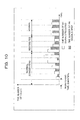
- the number of received M1 signals and the number of transmitted M4 signals, calculated at each predetermined monitoring time duration, change over time, as exemplified in FIG. 10 .
- the outline rectangles indicate the number of received M1 signals in the eNB 100
- the shaded rectangles indicate the number of transmitted M4 signals in the eNB 100.
- the number of received M1 signals can increase in comparison with the number of transmitted M4 signals.
- the communications network of the wireless communications system can fall in a congestion state.
- the eNB 100 when deciding that a difference between the number of received M1 signals and the number of transmitted M4 signals is equal to or larger than the threshold value Th1, decides that the communications network is in a congestion state, and restricts (halts) transmission of the M1 signals by the UE 200.
- the transmission restriction here means at least restriction with respect to new transmission of an M1 signal.
- restriction can be made with respect to transmission of the M1 signal which is retransmitted the number of times equal to or smaller than the threshold value X.
- the eNB 100 monitors the completion ratio of a connection sequence based on the number of received M1 signals (the number of started connection sequences) and also the number of transmittedM4 signals (the number of completed connection sequences), and then evaluates the presence and the absence of the congestion state based on this monitoring result. Then, the eNB 100 controls (performs restriction or lifting of the restriction) transmission in the UE 200 based on the monitoring result. Accordingly, the communications controlling method according to the present example makes it possible to early detect generation of the congestion state in the communications network, and also to early suppress the occurring congestion state.
- the constructions and the processes of the above described eNB 100 and UE 200 can be sift through in accordance with the necessity or appropriately combined with one another. Further, transmission of an M1 signal by the UE 200 is controlled (restricted) in the above described example. Likewise, transmission of the M3 signal by the UE 200 can be controlled (restricted).
- the completion ratio of the connection sequence is monitored.
- the evaluation of the congestion state in the communications network can be evaluated based on this monitoring result.
- the UE 200 can count the number of M3 signals retransmitted, and perform transmission control according to the number of times of the retransmission performed. Further, in the above described example, a description was made of a case where the eNB 100 and the UE 200 perform the above described communications controlling, but it is also possible to execute the communications controlling by other construction elements (entities) of the wireless communications system.
- the constructions and the processing of the eNB 100 and the UE 200, respectively, can be dispersedly arranged in the wireless communications system, and also can be arranged in a single device (for example, an eNB, UE, a wireless base station control device or the like).
- All examples and conditional language recited herein are intended for pedagogical purposes to aid the reader in understanding the invention and the concepts contributed by the inventor to furthering the art, and are to be construed as being without limitation to such specifically recited examples and conditions, nor does the organization of such examples in the specification relate to a showing of the superiority and inferiority of the invention.
- the various features may be implemented in hardware, or as software modules running on one or more processors. Features of one aspect may be applied to any of the other aspects.
- the invention also provides a computer program or a computer program product for carrying out any of the methods described herein, and a computer readable medium having stored thereon a program for carrying out any of the methods described herein.
- a computer program embodying the invention may be stored on a computer-readable medium, or it could, for example, be in the form of a signal such as a downloadable data signal provided from an Internet website, or it could be in any other form.
Landscapes
- Engineering & Computer Science (AREA)
- Computer Networks & Wireless Communication (AREA)
- Signal Processing (AREA)
- Mobile Radio Communication Systems (AREA)
Applications Claiming Priority (1)
| Application Number | Priority Date | Filing Date | Title |
|---|---|---|---|
| JP2008156941A JP2009303052A (ja) | 2008-06-16 | 2008-06-16 | 無線基地局、無線端末、通信制御方法及び無線通信システム |
Publications (2)
| Publication Number | Publication Date |
|---|---|
| EP2136584A2 true EP2136584A2 (fr) | 2009-12-23 |
| EP2136584A3 EP2136584A3 (fr) | 2011-06-01 |
Family
ID=41165244
Family Applications (1)
| Application Number | Title | Priority Date | Filing Date |
|---|---|---|---|
| EP09162615A Withdrawn EP2136584A3 (fr) | 2008-06-16 | 2009-06-12 | Station de base sans fil, terminal mobile, procédé de contrôle de communication, et système de communication sans fil |
Country Status (3)
| Country | Link |
|---|---|
| US (1) | US20090311967A1 (fr) |
| EP (1) | EP2136584A3 (fr) |
| JP (1) | JP2009303052A (fr) |
Cited By (2)
| Publication number | Priority date | Publication date | Assignee | Title |
|---|---|---|---|---|
| EP2512198A4 (fr) * | 2009-12-31 | 2012-11-14 | Huawei Tech Co Ltd | Procédé et appareil permettant une configuration de ressources basées sur la contention |
| US11201697B2 (en) | 2015-11-02 | 2021-12-14 | Sony Corporation | Information processing apparatus and communication system |
Families Citing this family (7)
| Publication number | Priority date | Publication date | Assignee | Title |
|---|---|---|---|---|
| GB2469229B (en) * | 2005-11-04 | 2011-02-02 | Nec Corp | Wireless communication system and method of controlling a transmission power |
| US8867999B2 (en) * | 2009-01-26 | 2014-10-21 | Qualcomm Incorporated | Downlink interference cancellation methods |
| JP5378268B2 (ja) * | 2010-02-23 | 2013-12-25 | 日本電信電話株式会社 | 無線基地局、無線通信システム、無線基地局のトラヒックレベル決定方法 |
| US8396072B2 (en) * | 2011-02-21 | 2013-03-12 | Renesas Mobile Corporation | Method and apparatus for channel traffic congestion avoidance in a mobile communication system |
| KR20140110947A (ko) * | 2012-01-20 | 2014-09-17 | 후지쯔 가부시끼가이샤 | 중단된 셀의 복구를 검출하기 위한 방법 및 장치 |
| US10085171B2 (en) | 2012-02-17 | 2018-09-25 | Nec Corporation | Method of controlling machine-type communications (MTC) in a wireless communications network |
| CN113747479B (zh) * | 2020-05-27 | 2022-12-02 | 荣耀终端有限公司 | 获取网络资源的方法、设备及系统 |
Citations (4)
| Publication number | Priority date | Publication date | Assignee | Title |
|---|---|---|---|---|
| JPH08336177A (ja) | 1995-06-07 | 1996-12-17 | Nippon Telegr & Teleph Corp <Ntt> | 無線パケット干渉検出方法、この方法を用いた無線パケットチャネル切替方法及び無線パケットチャネル切替・輻輳規制方法 |
| JPH10108260A (ja) | 1996-09-30 | 1998-04-24 | Toshiba Corp | 呼受付制御装置 |
| JP2002217956A (ja) | 2001-01-16 | 2002-08-02 | Ntt Docomo Inc | 呼受付制御方法、移動通信システム、及び基地局装置 |
| JP2005328317A (ja) | 2004-05-14 | 2005-11-24 | Fujitsu Ltd | 通信装置、再送制御方法 |
Family Cites Families (9)
| Publication number | Priority date | Publication date | Assignee | Title |
|---|---|---|---|---|
| EP1511346B1 (fr) * | 1999-03-10 | 2017-11-22 | Thomson Licensing SAS | Procédé et appareil de transmission d'un salve d'accès aléatoire |
| US6754501B1 (en) * | 2000-11-02 | 2004-06-22 | Motorola, Inc. | Media access adaptive control to improve system throughput |
| JP2004523940A (ja) * | 2000-11-28 | 2004-08-05 | インターデイジタル テクノロジー コーポレーション | 競合アクセス制御システムおよび方法 |
| DE60219276T2 (de) * | 2002-01-28 | 2008-01-03 | Lucent Technologies Inc. | Verfahren und Einrichtung zur wahlfreien Zugriffspaketübertragung durch Ausführung einer Laststeuerungsfunktionalität |
| US6631269B1 (en) * | 2002-05-23 | 2003-10-07 | Interdigital Technology Corporation | Signaling connection admission control in a wireless network |
| US7471654B2 (en) * | 2004-12-29 | 2008-12-30 | Alcatel-Lucent Usa Inc. | Channel assignment based on service type and wireless communication environment |
| US8238235B2 (en) * | 2005-06-21 | 2012-08-07 | Toshiba America Research, Inc. | Admission control for contention-based access to a wireless communication medium |
| JP4805080B2 (ja) * | 2006-09-29 | 2011-11-02 | 株式会社エヌ・ティ・ティ・ドコモ | 通信制御方法、無線基地局及び無線制御局 |
| KR101366332B1 (ko) * | 2007-04-19 | 2014-02-21 | 엘지전자 주식회사 | 통신 시스템에서의 데이터 블록 재전송 방법 |
-
2008
- 2008-06-16 JP JP2008156941A patent/JP2009303052A/ja not_active Withdrawn
-
2009
- 2009-06-05 US US12/479,183 patent/US20090311967A1/en not_active Abandoned
- 2009-06-12 EP EP09162615A patent/EP2136584A3/fr not_active Withdrawn
Patent Citations (4)
| Publication number | Priority date | Publication date | Assignee | Title |
|---|---|---|---|---|
| JPH08336177A (ja) | 1995-06-07 | 1996-12-17 | Nippon Telegr & Teleph Corp <Ntt> | 無線パケット干渉検出方法、この方法を用いた無線パケットチャネル切替方法及び無線パケットチャネル切替・輻輳規制方法 |
| JPH10108260A (ja) | 1996-09-30 | 1998-04-24 | Toshiba Corp | 呼受付制御装置 |
| JP2002217956A (ja) | 2001-01-16 | 2002-08-02 | Ntt Docomo Inc | 呼受付制御方法、移動通信システム、及び基地局装置 |
| JP2005328317A (ja) | 2004-05-14 | 2005-11-24 | Fujitsu Ltd | 通信装置、再送制御方法 |
Cited By (3)
| Publication number | Priority date | Publication date | Assignee | Title |
|---|---|---|---|---|
| EP2512198A4 (fr) * | 2009-12-31 | 2012-11-14 | Huawei Tech Co Ltd | Procédé et appareil permettant une configuration de ressources basées sur la contention |
| US9357561B2 (en) | 2009-12-31 | 2016-05-31 | Huawei Technologies Co., Ltd. | Information feedback method and apparatus |
| US11201697B2 (en) | 2015-11-02 | 2021-12-14 | Sony Corporation | Information processing apparatus and communication system |
Also Published As
| Publication number | Publication date |
|---|---|
| JP2009303052A (ja) | 2009-12-24 |
| US20090311967A1 (en) | 2009-12-17 |
| EP2136584A3 (fr) | 2011-06-01 |
Similar Documents
| Publication | Publication Date | Title |
|---|---|---|
| EP2136584A2 (fr) | Station de base sans fil, terminal mobile, procédé de contrôle de communication, et système de communication sans fil | |
| CN105934984B (zh) | 用于设备到设备(d2d)无线通信的半永久性信道占用的组间控制 | |
| EP3445132B1 (fr) | Appareil d'utilisateur et procédé de commande de retour | |
| CN111937437A (zh) | 装置、方法和计算机程序 | |
| US10367617B2 (en) | Method, base station and user equipment for transmission | |
| EP3457802A1 (fr) | Station sans fil et procédé de communication | |
| US9801212B2 (en) | User equipment and method for resource allocation | |
| EP2111051A1 (fr) | Terminal, procédé de transmission de signal d'accès aléatoire et station de base | |
| Pratas et al. | Random access for machine-type communication based on bloom filtering | |
| KR102214852B1 (ko) | 센싱 기반의 랜덤액세스 방법 및 장치 | |
| US10313059B2 (en) | Data sending feedback method and apparatus, and data sending method and apparatus | |
| US11469926B2 (en) | Method for transmitting signals and corresponding terminals, and base stations | |
| EP3573400B1 (fr) | Procédé pour réattribuer un indice de séquence racine, et appareil associé | |
| CN117561783A (zh) | 在拥塞情况下用于随机接入的方法、装置和计算机可读介质 | |
| CN103369701B (zh) | 一种随机接入的方法及装置 | |
| KR101571899B1 (ko) | 인지 무선 시스템에서의 채널 선택 장치 및 방법 | |
| EP3796735B1 (fr) | Dispositif d'utilisateur, appareil de station de base et procédé mis en oeuvre par un dispositif d'utilisateur | |
| EP3562250B1 (fr) | Procédés et appareils d'accès aléatoire | |
| KR101707163B1 (ko) | 무선 통신 시스템에서의 적응적 랜덤 액세스 제어 및 자원 할당 방법과 장치 | |
| KR102169527B1 (ko) | PS-Poll 전송 방법 및 그 장치 | |
| Kim et al. | Transmit power optimization for prioritized random access in OFDMA based systems | |
| US12621872B2 (en) | Random access | |
| CN106900076B (zh) | 一种随机接入参数的更新方法及相关设备 | |
| US10512077B2 (en) | Method and apparatus for performing fractional subframe transmission | |
| US20240163928A1 (en) | Random access |
Legal Events
| Date | Code | Title | Description |
|---|---|---|---|
| PUAI | Public reference made under article 153(3) epc to a published international application that has entered the european phase |
Free format text: ORIGINAL CODE: 0009012 |
|
| AK | Designated contracting states |
Kind code of ref document: A2 Designated state(s): AT BE BG CH CY CZ DE DK EE ES FI FR GB GR HR HU IE IS IT LI LT LU LV MC MK MT NL NO PL PT RO SE SI SK TR |
|
| PUAL | Search report despatched |
Free format text: ORIGINAL CODE: 0009013 |
|
| AK | Designated contracting states |
Kind code of ref document: A3 Designated state(s): AT BE BG CH CY CZ DE DK EE ES FI FR GB GR HR HU IE IS IT LI LT LU LV MC MK MT NL NO PL PT RO SE SI SK TR |
|
| STAA | Information on the status of an ep patent application or granted ep patent |
Free format text: STATUS: THE APPLICATION IS DEEMED TO BE WITHDRAWN |
|
| 18D | Application deemed to be withdrawn |
Effective date: 20111202 |