EP2138265A1 - Machine-outil - Google Patents
Machine-outil Download PDFInfo
- Publication number
- EP2138265A1 EP2138265A1 EP08721748A EP08721748A EP2138265A1 EP 2138265 A1 EP2138265 A1 EP 2138265A1 EP 08721748 A EP08721748 A EP 08721748A EP 08721748 A EP08721748 A EP 08721748A EP 2138265 A1 EP2138265 A1 EP 2138265A1
- Authority
- EP
- European Patent Office
- Prior art keywords
- axis direction
- feed
- fixing table
- support
- work fixing
- Prior art date
- Legal status (The legal status is an assumption and is not a legal conclusion. Google has not performed a legal analysis and makes no representation as to the accuracy of the status listed.)
- Granted
Links
Images







Classifications
-
- B—PERFORMING OPERATIONS; TRANSPORTING
- B23—MACHINE TOOLS; METAL-WORKING NOT OTHERWISE PROVIDED FOR
- B23Q—DETAILS, COMPONENTS, OR ACCESSORIES FOR MACHINE TOOLS, e.g. ARRANGEMENTS FOR COPYING OR CONTROLLING; MACHINE TOOLS IN GENERAL CHARACTERISED BY THE CONSTRUCTION OF PARTICULAR DETAILS OR COMPONENTS; COMBINATIONS OR ASSOCIATIONS OF METAL-WORKING MACHINES, NOT DIRECTED TO A PARTICULAR RESULT
- B23Q1/00—Members which are comprised in the general build-up of a form of machine, particularly relatively large fixed members
- B23Q1/25—Movable or adjustable work or tool supports
- B23Q1/44—Movable or adjustable work or tool supports using particular mechanisms
- B23Q1/56—Movable or adjustable work or tool supports using particular mechanisms with sliding pairs only, the sliding pairs being the first two elements of the mechanism
-
- B—PERFORMING OPERATIONS; TRANSPORTING
- B23—MACHINE TOOLS; METAL-WORKING NOT OTHERWISE PROVIDED FOR
- B23Q—DETAILS, COMPONENTS, OR ACCESSORIES FOR MACHINE TOOLS, e.g. ARRANGEMENTS FOR COPYING OR CONTROLLING; MACHINE TOOLS IN GENERAL CHARACTERISED BY THE CONSTRUCTION OF PARTICULAR DETAILS OR COMPONENTS; COMBINATIONS OR ASSOCIATIONS OF METAL-WORKING MACHINES, NOT DIRECTED TO A PARTICULAR RESULT
- B23Q1/00—Members which are comprised in the general build-up of a form of machine, particularly relatively large fixed members
- B23Q1/25—Movable or adjustable work or tool supports
- B23Q1/44—Movable or adjustable work or tool supports using particular mechanisms
- B23Q1/48—Movable or adjustable work or tool supports using particular mechanisms with sliding pairs and rotating pairs
-
- B—PERFORMING OPERATIONS; TRANSPORTING
- B23—MACHINE TOOLS; METAL-WORKING NOT OTHERWISE PROVIDED FOR
- B23B—TURNING; BORING
- B23B41/00—Boring or drilling machines or devices specially adapted for particular work; Accessories specially adapted therefor
- B23B41/12—Boring or drilling machines or devices specially adapted for particular work; Accessories specially adapted therefor for forming working surfaces of cylinders, of bearings, e.g. in heads of driving rods, or of other engine parts
-
- B—PERFORMING OPERATIONS; TRANSPORTING
- B23—MACHINE TOOLS; METAL-WORKING NOT OTHERWISE PROVIDED FOR
- B23B—TURNING; BORING
- B23B5/00—Turning-machines or devices specially adapted for particular work; Accessories specially adapted therefor
- B23B5/18—Turning-machines or devices specially adapted for particular work; Accessories specially adapted therefor for turning crankshafts, eccentrics, or cams, e.g. crankpin lathes
-
- B—PERFORMING OPERATIONS; TRANSPORTING
- B23—MACHINE TOOLS; METAL-WORKING NOT OTHERWISE PROVIDED FOR
- B23Q—DETAILS, COMPONENTS, OR ACCESSORIES FOR MACHINE TOOLS, e.g. ARRANGEMENTS FOR COPYING OR CONTROLLING; MACHINE TOOLS IN GENERAL CHARACTERISED BY THE CONSTRUCTION OF PARTICULAR DETAILS OR COMPONENTS; COMBINATIONS OR ASSOCIATIONS OF METAL-WORKING MACHINES, NOT DIRECTED TO A PARTICULAR RESULT
- B23Q1/00—Members which are comprised in the general build-up of a form of machine, particularly relatively large fixed members
- B23Q1/25—Movable or adjustable work or tool supports
- B23Q1/44—Movable or adjustable work or tool supports using particular mechanisms
-
- B—PERFORMING OPERATIONS; TRANSPORTING
- B23—MACHINE TOOLS; METAL-WORKING NOT OTHERWISE PROVIDED FOR
- B23Q—DETAILS, COMPONENTS, OR ACCESSORIES FOR MACHINE TOOLS, e.g. ARRANGEMENTS FOR COPYING OR CONTROLLING; MACHINE TOOLS IN GENERAL CHARACTERISED BY THE CONSTRUCTION OF PARTICULAR DETAILS OR COMPONENTS; COMBINATIONS OR ASSOCIATIONS OF METAL-WORKING MACHINES, NOT DIRECTED TO A PARTICULAR RESULT
- B23Q1/00—Members which are comprised in the general build-up of a form of machine, particularly relatively large fixed members
- B23Q1/25—Movable or adjustable work or tool supports
- B23Q1/44—Movable or adjustable work or tool supports using particular mechanisms
- B23Q1/48—Movable or adjustable work or tool supports using particular mechanisms with sliding pairs and rotating pairs
- B23Q1/4852—Movable or adjustable work or tool supports using particular mechanisms with sliding pairs and rotating pairs a single sliding pair followed perpendicularly by a single rotating pair
-
- B—PERFORMING OPERATIONS; TRANSPORTING
- B23—MACHINE TOOLS; METAL-WORKING NOT OTHERWISE PROVIDED FOR
- B23Q—DETAILS, COMPONENTS, OR ACCESSORIES FOR MACHINE TOOLS, e.g. ARRANGEMENTS FOR COPYING OR CONTROLLING; MACHINE TOOLS IN GENERAL CHARACTERISED BY THE CONSTRUCTION OF PARTICULAR DETAILS OR COMPONENTS; COMBINATIONS OR ASSOCIATIONS OF METAL-WORKING MACHINES, NOT DIRECTED TO A PARTICULAR RESULT
- B23Q1/00—Members which are comprised in the general build-up of a form of machine, particularly relatively large fixed members
- B23Q1/25—Movable or adjustable work or tool supports
- B23Q1/44—Movable or adjustable work or tool supports using particular mechanisms
- B23Q1/50—Movable or adjustable work or tool supports using particular mechanisms with rotating pairs only, the rotating pairs being the first two elements of the mechanism
- B23Q1/54—Movable or adjustable work or tool supports using particular mechanisms with rotating pairs only, the rotating pairs being the first two elements of the mechanism two rotating pairs only
-
- B—PERFORMING OPERATIONS; TRANSPORTING
- B23—MACHINE TOOLS; METAL-WORKING NOT OTHERWISE PROVIDED FOR
- B23Q—DETAILS, COMPONENTS, OR ACCESSORIES FOR MACHINE TOOLS, e.g. ARRANGEMENTS FOR COPYING OR CONTROLLING; MACHINE TOOLS IN GENERAL CHARACTERISED BY THE CONSTRUCTION OF PARTICULAR DETAILS OR COMPONENTS; COMBINATIONS OR ASSOCIATIONS OF METAL-WORKING MACHINES, NOT DIRECTED TO A PARTICULAR RESULT
- B23Q1/00—Members which are comprised in the general build-up of a form of machine, particularly relatively large fixed members
- B23Q1/25—Movable or adjustable work or tool supports
- B23Q1/64—Movable or adjustable work or tool supports characterised by the purpose of the movement
-
- B—PERFORMING OPERATIONS; TRANSPORTING
- B23—MACHINE TOOLS; METAL-WORKING NOT OTHERWISE PROVIDED FOR
- B23B—TURNING; BORING
- B23B2215/00—Details of workpieces
- B23B2215/20—Crankshafts
-
- Y—GENERAL TAGGING OF NEW TECHNOLOGICAL DEVELOPMENTS; GENERAL TAGGING OF CROSS-SECTIONAL TECHNOLOGIES SPANNING OVER SEVERAL SECTIONS OF THE IPC; TECHNICAL SUBJECTS COVERED BY FORMER USPC CROSS-REFERENCE ART COLLECTIONS [XRACs] AND DIGESTS
- Y10—TECHNICAL SUBJECTS COVERED BY FORMER USPC
- Y10T—TECHNICAL SUBJECTS COVERED BY FORMER US CLASSIFICATION
- Y10T408/00—Cutting by use of rotating axially moving tool
- Y10T408/55—Cutting by use of rotating axially moving tool with work-engaging structure other than Tool or tool-support
- Y10T408/561—Having tool-opposing, work-engaging surface
- Y10T408/5614—Angularly adjustable surface
-
- Y—GENERAL TAGGING OF NEW TECHNOLOGICAL DEVELOPMENTS; GENERAL TAGGING OF CROSS-SECTIONAL TECHNOLOGIES SPANNING OVER SEVERAL SECTIONS OF THE IPC; TECHNICAL SUBJECTS COVERED BY FORMER USPC CROSS-REFERENCE ART COLLECTIONS [XRACs] AND DIGESTS
- Y10—TECHNICAL SUBJECTS COVERED BY FORMER USPC
- Y10T—TECHNICAL SUBJECTS COVERED BY FORMER US CLASSIFICATION
- Y10T408/00—Cutting by use of rotating axially moving tool
- Y10T408/83—Tool-support with means to move Tool relative to tool-support
-
- Y—GENERAL TAGGING OF NEW TECHNOLOGICAL DEVELOPMENTS; GENERAL TAGGING OF CROSS-SECTIONAL TECHNOLOGIES SPANNING OVER SEVERAL SECTIONS OF THE IPC; TECHNICAL SUBJECTS COVERED BY FORMER USPC CROSS-REFERENCE ART COLLECTIONS [XRACs] AND DIGESTS
- Y10—TECHNICAL SUBJECTS COVERED BY FORMER USPC
- Y10T—TECHNICAL SUBJECTS COVERED BY FORMER US CLASSIFICATION
- Y10T409/00—Gear cutting, milling, or planing
- Y10T409/30—Milling
- Y10T409/304088—Milling with means to remove chip
-
- Y—GENERAL TAGGING OF NEW TECHNOLOGICAL DEVELOPMENTS; GENERAL TAGGING OF CROSS-SECTIONAL TECHNOLOGIES SPANNING OVER SEVERAL SECTIONS OF THE IPC; TECHNICAL SUBJECTS COVERED BY FORMER USPC CROSS-REFERENCE ART COLLECTIONS [XRACs] AND DIGESTS
- Y10—TECHNICAL SUBJECTS COVERED BY FORMER USPC
- Y10T—TECHNICAL SUBJECTS COVERED BY FORMER US CLASSIFICATION
- Y10T409/00—Gear cutting, milling, or planing
- Y10T409/30—Milling
- Y10T409/304536—Milling including means to infeed work to cutter
- Y10T409/305544—Milling including means to infeed work to cutter with work holder
- Y10T409/3056—Milling including means to infeed work to cutter with work holder and means to selectively position work
-
- Y—GENERAL TAGGING OF NEW TECHNOLOGICAL DEVELOPMENTS; GENERAL TAGGING OF CROSS-SECTIONAL TECHNOLOGIES SPANNING OVER SEVERAL SECTIONS OF THE IPC; TECHNICAL SUBJECTS COVERED BY FORMER USPC CROSS-REFERENCE ART COLLECTIONS [XRACs] AND DIGESTS
- Y10—TECHNICAL SUBJECTS COVERED BY FORMER USPC
- Y10T—TECHNICAL SUBJECTS COVERED BY FORMER US CLASSIFICATION
- Y10T409/00—Gear cutting, milling, or planing
- Y10T409/30—Milling
- Y10T409/306664—Milling including means to infeed rotary cutter toward work
- Y10T409/307448—Milling including means to infeed rotary cutter toward work with work holder
- Y10T409/307504—Indexable
-
- Y—GENERAL TAGGING OF NEW TECHNOLOGICAL DEVELOPMENTS; GENERAL TAGGING OF CROSS-SECTIONAL TECHNOLOGIES SPANNING OVER SEVERAL SECTIONS OF THE IPC; TECHNICAL SUBJECTS COVERED BY FORMER USPC CROSS-REFERENCE ART COLLECTIONS [XRACs] AND DIGESTS
- Y10—TECHNICAL SUBJECTS COVERED BY FORMER USPC
- Y10T—TECHNICAL SUBJECTS COVERED BY FORMER US CLASSIFICATION
- Y10T409/00—Gear cutting, milling, or planing
- Y10T409/30—Milling
- Y10T409/306664—Milling including means to infeed rotary cutter toward work
- Y10T409/307672—Angularly adjustable cutter head
-
- Y—GENERAL TAGGING OF NEW TECHNOLOGICAL DEVELOPMENTS; GENERAL TAGGING OF CROSS-SECTIONAL TECHNOLOGIES SPANNING OVER SEVERAL SECTIONS OF THE IPC; TECHNICAL SUBJECTS COVERED BY FORMER USPC CROSS-REFERENCE ART COLLECTIONS [XRACs] AND DIGESTS
- Y10—TECHNICAL SUBJECTS COVERED BY FORMER USPC
- Y10T—TECHNICAL SUBJECTS COVERED BY FORMER US CLASSIFICATION
- Y10T409/00—Gear cutting, milling, or planing
- Y10T409/30—Milling
- Y10T409/30784—Milling including means to adustably position cutter
- Y10T409/307952—Linear adjustment
- Y10T409/308232—Linear adjustment and angular adjustment
-
- Y—GENERAL TAGGING OF NEW TECHNOLOGICAL DEVELOPMENTS; GENERAL TAGGING OF CROSS-SECTIONAL TECHNOLOGIES SPANNING OVER SEVERAL SECTIONS OF THE IPC; TECHNICAL SUBJECTS COVERED BY FORMER USPC CROSS-REFERENCE ART COLLECTIONS [XRACs] AND DIGESTS
- Y10—TECHNICAL SUBJECTS COVERED BY FORMER USPC
- Y10T—TECHNICAL SUBJECTS COVERED BY FORMER US CLASSIFICATION
- Y10T409/00—Gear cutting, milling, or planing
- Y10T409/30—Milling
- Y10T409/30868—Work support
- Y10T409/30896—Work support with angular adjustment
Definitions
- the present invention relates to a machine tool for machining an oblique hole through a shaft-like work such as a crank shaft.
- a longitudinal rotary spindle is provided on a horizontal top surface of a bed to be movable in triaxial directions (longitudinal direction, lateral direction, vertical direction) intersecting one another perpendicularly, a swiveling table turning around a vertical axis is provided on the top surface facing to the spindle on the longitudinal direction to protrude upwardly, and a work fixing table is fixed on the top surface of the swiveling table (see references D1 and D2).
- an operation is carried out by holding a work horizontal on the top surface of the work fixing table through a work main-axis rotary index support device, turning the swiveling table around a vertical pivot (B axis) and rotating the work around its reference axis through a work support/rotate device in accordance with the necessity whereby the oblique hole to be made is along to the same longitudinal direction as the rotary spindle, and thereafter forwardly moving the work as facing a rotating center of the rotary spindle to a position of the oblique hole and rotating the rotary spindle and a tool fixed on the tip thereof.
- the conventional machine tool has the following problems.
- the present invention aims to provide a machine tool to settle the above mentioned problems.
- a machine tool related to the first invention is so characterized that a pair of guide tracks respectively passing two positions separated in the X axis direction of the stationary body section and in the Z axis direction intersecting the X axis direction perpendicularly are allowed to guide feed tables to be movable independently, and a support/feed/turn output member is arranged to bridge the feed tables on the guide tracks.
- one feed table and support/feed/turn output member are coupled to relatively rotate about a line in the Y axis direction which intersects both the X axis direction and the Z axis direction perpendicularly
- the other feed table and support/feed/turn output member are coupled to be relatively rotatable about a line in the Y axis direction and to be relatively movable in a specific direction related to the positions of the both feed tables.
- the Z axis direction preferably intersects the X axis direction perpendicularly, it can intersect the X axis direction by optional angles.
- a machine tool related to the second invention is so constructed, on the assumption of the first invention, that a rotary spindle is provided on the stationary body section to be movable in the X axis direction and the Y axis direction and to be rotatable about a line in the Z axis direction, and that the support/feed/turn output member facing to the rotary spindle through the Z axis direction is formed in a work fixing table.
- a machine tool related to the third invention is so constructed, on the assumption of the first invention or the second invention, that a displacement regulating means for regulating relative displacement in a specific direction is provided.
- a machine tool related to the fourth invention is so constructed, on the assumption of the first invention, that the work fixing table is provided on the stationary body section to be movable in the X axis direction and the Y axis direction, and that the rotary spindle is installed on the support/feed/turn output member facing to the work fixing table through the Z axis direction.
- a machine tool related to the fifth invention is so constructed, on the assumption of the first invention, the second invention or the fourth invention, that the X axis direction, the Y axis direction and the Z axis direction respectively correspond to lateral direction, vertical direction and longitudinal direction, or that the X axis direction, the Y axis direction and the Z axis direction respectively correspond to the lateral direction, the longitudinal direction and the vertical direction.
- a machine tool related to the sixth invention is so constructed, on the assumption of the first invention, the second invention or the fourth invention, that the X axis direction, the Y axis direction and the Z axis direction respectively correspond to the lateral direction, the vertical direction and the longitudinal direction, a portion of the stationary body section between the pair of guide tracks serves as a through hole in the Y axis direction, and a feeding device for moving the feed table in the Z axis direction is arranged therein.
- a machine tool related to the seventh invention is so constructed, on the assumption of the first invention, the second invention or the fourth invention, that the X axis direction, the Y axis direction and the Z axis direction respectively correspond to the lateral direction, the vertical direction and the longitudinal direction, a through hole in the Y axis direction is formed to the stationary body section, a pair of track support members is provided near the upper end thereof to bridge in the Z axis direction as a part of the stationary body section, and the feeding device for moving the feed table in the Z axis direction is arranged therein.
- the through hole has an inner peripheral guide way whose section is gradually reduced downward, and the guide tracks are respectively supported by the track support members.
- a machine tool related to the eighth invention is so constructed, on the assumption of the second invention or the fourth invention, that a position on the Y axis direction of the work fixing surface of the work fixing table almost coincides with a position on the Y axis direction of the guide track for guiding the rotary spindle in the X axis direction.
- a machine tool related to the ninth invention is so constructed, on the assumption of the first invention or the second invention, that driving devices for moving the feed tables in the Z axis direction are respectively arranged at the positions in the Z axis direction at the fixed depth on the Y axis direction of the stationary body section.
- the Z axial guide tracks respectively passing two positions separated in the X axis direction on a specific plane of the stationary body section and intersecting the X axis direction are allowed to guide feed tables to be movable independently, and the support/feed/turn output member is arranged to bridge the feed tables on the guide tracks.
- One feed table and support/feed/turn output member are coupled to be relatively rotatable about the line in the Y axis direction for intersecting perpendicularly both the X axis direction and the Z axis direction, and the other feed table and support/feed/turn output member are coupled to be relatively rotatable about the line in the Y axis direction and to be relatively displaceable in the specific direction related to the positions of the both feed tables.
- the support/feed/turn output member can move parallel in the Z axis direction and turn around the line of the Y axis direction on the stationary body section due to the displacement of the feed tables in the Z axis direction even without a conventional comparatively large swiveling table protruded from the stationary body section.
- the support/feed/turn output member can be located near the stationary body section.
- the non-cutting time of the tool while carrying out a machining program for one work is shortened, and the machining can be efficiently carried out.
- the support/feed/turn output member serves as the work fixing table
- the two positions separated in the longitudinal direction on the work fixing table are supported by the two feed tables and the work fixing table overhanging from each of the feed tables lowers even if the work fixing table supports a long shaft-like work such as a crank shaft.
- the work fixing table supports a long shaft-like work such as a crank shaft.
- a straight hole in optional direction formed on a radius surface including a rotating central axis of the work can be machined efficiently and high-accurately.
- the work fixing table is parallel moved in the Z axis direction in accordance with the necessity, the rotary spindle does not need to be moved in the Z axis direction.
- the third invention in addition to the same effect as the first invention or the second invention, the following effect can be obtained. That is, because the means for regulating relative displacement in the specific direction is provided, even if the feed tables and the support/feed/turn output member are guided in the specific direction by a guiding means having a comparatively small rigidity, the relative displacement between the feed tables and the support/feed/turn output member can be regulated by the means for regulating relative displacement. According to this, the coupling rigidity between the feed tables and the support/feed/turn output member is drastically increased, and the fixing of the position of the support/feed/turn output member on the stationary body section is enhanced. In supporting the work or the rotary spindle to the support/feed/turn output member, it is possible to enhance the machining accuracy of the work.
- the following effect can be obtained. That is, because the rotary spindle is mounted on the support/feed/turn output member, the rotary spindle can be turned around the imaginary pivot in the Y axis direction.
- the rotary spindle is turned to the specific direction parallel to both of the X axis direction and the Z axis direction against the work fixing table and besides the work is supported on the work fixing table through the position-dividing device around a specific line (preferably a line in the X axis direction) parallel to both of the X axis direction and the Z axis direction, it is possible to machine the straight hole in optional direction formed on the radius surface including the rotating central axis of the work efficiently and high-accurately.
- a specific line preferably a line in the X axis direction
- the work fixing table is moved parallel to the Z axis direction together with the support/feed/turn output member and turned around the imaginary pivot in the Y axis direction, and therefore, it is not necessary to move the work parallel to the Z axis direction and to turn it around the imaginary pivot in the Y axis direction.
- the fifth invention in addition to the same effect as the first invention, the second invention or the fourth invention, the following effect can be obtained. That is, in corresponding the X axis direction, the Y axis direction and the Z axis direction to lateral direction, vertical direction and longitudinal direction respectively, even if the feed table moves extendedly in the Z axis direction, it can be installed and stably stationed to the lower height.
- the work fixing table is parallel moved or turning-displaced in the longitudinal direction parallel to a horizontal surface, and the rotary spindle is tuned to the longitudinal direction, parallel moved in the lateral direction and in the vertical direction, and turned around the line of the longitudinal direction.
- the work fixing table is not parallel moved in the lateral direction, and the body width is held down small when the lateral length of the work fixing table is long.
- the rotary spindle is parallel moved or turning-displaced in the longitudinal direction parallel to the horizontal surface, and the work fixing table is parallel moved in the lateral direction and the vertical direction. Accordingly, the rotary spindle is not be parallel moved in the lateral direction and the work fixing table is parallel moved in the lateral direction, and therefore, a rational machining can be carried out when the lateral length of the work is short.
- a setting space in the longitudinal direction can be lowered even if the feed table extendedly moves in the Z axis direction.
- the work fixing table is parallel moved in the vertical direction on a plane parallel to both of the lateral direction and the longitudinal direction or turning-displaced around the imaginary pivot in the longitudinal direction, and the rotary spindle is turned to the vertical direction and parallel moved in the lateral direction and the longitudinal direction and rotated around the line of the vertical direction. Accordingly, the work fixing table is not parallel moved in the lateral direction, and the body width can be held small when the lateral length is long.
- the rotary spindle is parallel moved in the vertical direction on the plane parallel to both of the lateral direction and the vertical direction or turning-displaced around the imaginary pivot in the longitudinal direction, and the work fixing table is parallel moved in the lateral direction and the longitudinal direction. Accordingly, the rotary spindle is not parallel moved in the lateral direction and the work fixing table is parallel moved in the lateral direction and therefore, the machining can be rationally carried out when the lateral length of the work is short.
- the rotary spindle is turned to the vertical direction, even if the rotary spindle protrudes from the supported position, the rotary spindle is controlled from displacing in a direction intersecting perpendicularly a line of the rotating center. Therefore, the machining can be carried out with high accuracy.
- the through hole has the chips generated during the machining dropped below the stationary body section without needing help and serves as a hollow place for receiving a feeding device that moves the feed table in the Z axis direction.
- the second invention it is possible to drop the chips accumulated on the work fixing table into the through hole in moving the work fixing table over the through hole. Therefore, the chips are cleaned easily.
- the seventh invention in addition to the same effect as the sixth invention, the following effect can be obtained. That is, it is possible to drop even chips dropped at the center of the opposite side of the guide tracks into the through hole, thereby further enhancing the effect of the sixth invention. Besides, even the chips generated in cutting due to the mist coolant supply hardly remain behind on the stationary body section, and therefore, the machining can be carried out with high accuracy. Furthermore, since the rigidity necessary for the stationary body section can be secured by the track supporting sections, it is possible to make the stationary body section lightweight without decreasing the rigidity excessively.
- the eighth invention in addition to the same effect as the second invention or the fourth invention, the following effect can be obtained. That is, since the X axial guide tracks of the rotary spindle approach the stationary body section like the work fixing table, the rotary spindle can approach the stationary body section like the work supported on the work fixing table. Accordingly, it is possible to increase the supporting rigidity of the work or the rotary spindle on the stationary body section.
- the ninth invention in addition to the same effect as the first invention or the fourth invention, the following effect can be obtained. That is, since the machine parts are simply arranged on the stationary body section, it is possible to easily discharge and clean the chips. Besides, it is possible to effectively decrease a distance from the supporting section of the stationary body section to the rotary spindle or the work fixing table.
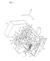
- Fig.1 is a perspective view seen from forward upper of a machining center of a numerical control machine tool related to the present invention
- Fig. 2 is a perspective view seen from rearward upper
- Fig. 3 is a front view
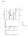
- Fig. 4 is a bottom view
- Fig. 5 is an explanatory view of the machining center seen from the side.
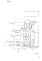
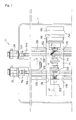
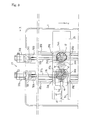
- Fig. 6 is a partial front view of a work supporting section of the machining center seen from the front
- Fig. 7 is a sectional view taken on line A-A therein
- Fig. 8 is a sectional view taken on line B-B therein.
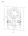
- Fig. 9 is an enlarged sectional view seen from the top, showing the circumference of the second connecting portion of the machining center.
- Fig. 9 is an enlarged sectional view seen from the top, showing the circumference of the second connecting portion of the machining center.
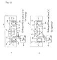
- Fig. 10 is an enlarged sectional view taken on line C-C in Fig. 6 .
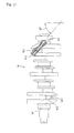
- Fig. 11 is a front view of a work.
- Fig. 12 is a plane view showing a work fixing table is turned about a line of Y axis direction.
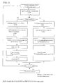
- Fig. 13 is a flow view showing an example of control through a computer numerical control gear.
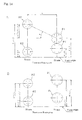
- Fig. 14 is a plane view explaining a movement of an axis portion correspondent to the flow view in Fig. 13 .
- 1 is a bed serving as a stationary body section, and thereon, a column 2, a work supporting section 4 and an ATC device 5 are provided.
- a controller box 6 is arranged at the rear side of the bed 1, and a computer numerical control gear and hydraulic high-pressure apparatuses are incorporated therein.
- the bed 1, as shown in Fig.4 comprises a leg 1A formed in a T letter shape viewed from the bottom and a supporting face 1B larger than the leg 1A.
- the supporting face 1B is formed integrally on the leg 1A.
- the top portion of the T letter shape is located at the rear side.
- the rear portion 1a of the supporting face 1B is formed so thick that its top surface is higher than the forward thereof by one step.
- the supporting face 1B more forward than the rear portion 1a has a top surface a2 comprising a broad single horizontal surface.
- Fences 1b, 1c, 1d which are higher than the top surface a2 are provided at the front edge, the left edge and the right edge of the top surface a2 respectively, and besides, a front end face a3 of the rear portion 1a is located to the rear edge of the top surface a2.
- a large through hole a4 having a rectangular shape seen from the top is formed in a vertical direction (Y axis direction) to the bed 1 in front of the leg 1A.
- a supporting bar 6a shaped as a hook protrudes from the leg 1A, and a control panel 6b for the computer numerical control gear is fixed on the top end of the supporting bar 6a.
- the column 2 is made in a body of a lower plate 2A shaped as a triangle seen from the top, a right side plate 2B shaped as a trapezoid seen from the side, a left side plate 2C and an upper plate 2D, being supported on the rear portion 1a of the bed 1 so as to be movable in the lateral direction (X axis direction) through an X axial guide means 7.
- the X axial guide means 7 has a pair of lateral guide tracks 8a, 8b on the top surfaces in front and rear sides of the straight groove a1 of the rear portion 1a, comprising plenty of guided bodies (for example: two guided bodies) 9a and at least one guided body 9b.
- the guided bodies 9a are provided to left and right two positions of the forward bottom surface of the lower plate 2A to be guided by the forward lateral guide track 8a simultaneously.
- the guided body 9b is provided on the rearward bottom surface of the lower plate 2A (see Fig. 5 ).
- the driving means 10 comprises a servomotor 11, a ball screw 12 and a not-illustrated nut for column.
- the servomotor 11 is fixed on the left end of the groove a1.
- the ball screw 12 is laterally combined to the output axis of the servomotor 11 and arranged in the groove a1.
- the not-illustrated nut for column is fixed on the bottom surface of the lower plate 2A, and therein the ball screw 12 is screwed.
- the servomotor 11 rotates through the computer numerical control gear in the control box 6, accordingly the column 2 moves laterally on the guide tracks 8a, 8b through the ball screw 12 and the nut for column.
- a spindle device 13 is supported by the column 2 to be movable in the vertical direction (Y axis direction), comprising a support plate 14 movable in the Y axis direction, a Z axial spindle guide cylinder 15, a rotary spindle 17 and a spindle motor 18.
- the support plate 14 comprises a plane parallel to both the X axis direction and the Y axis direction.
- the cylinder 15 is fixed on the almost center of the support plate 14 so as to protrude forward.
- the rotary spindle 17 is inserted into the cylinder 15 so as to freely rotate, having an exchangeable tool holder 16 on the front end.
- the spindle motor 18 is fixed on the rear of the support plate 14 in a body, giving rotation driving force to the rear end of the rotary spindle 17.
- the support plate 14 is arranged at the front surface of the column 2, being guided to be movable in the vertical direction (Y axis direction) to the column 2 through a Y axial guide means 19.
- the guide means 19 has a pair of left and right vertical guide tracks 20a, 20b provided on the front end face of the right side plate 2B and the front end face of the left side plate 2C, comprising a plenty of guided bodies 21a (for example two) and a plenty of guided bodies 21b (for example two).
- the guided bodies 21a are provided at a plenty of upper and lower portions (for example two) of the rearward left end of the support plate 14 to be guided by the left vertical guide means 20a simultaneously.
- the guided bodies 21b are provided at a plenty of upper and lower portions (for example two) of the rearward right end of the support plate 14 to be guided by the right vertical guide means 20b simultaneously.
- a Y axial driving means 22 is provided between the column 2 and the spindle gear 13.
- the driving means 22 comprises a servomotor 23, a ball screw 24 and a not-illustrated nut for spindle gear.
- the servomotor 23 is fixed at the right portion of the top surface of the upper plate 2D.
- the ball screw 24 is combined to the output axis of the servomotor 23 and arranged vertically.
- the not-illustrated nut for spindle gear is fixed to the rear surface of the support plate 14, and therein, the ball screw 24 is screwed.
- the servomotor 23 rotates through the computer numerical control gear in the control box 6, accordingly the spindle gear 13 moves vertically on the guide tracks 20a, 20b through the ball screw 24 and the nut for spindle gear.
- the work supporting section 4 comprises a work fixing table 25A and a work main-axis rotary index support mechanism 26.
- the work fixing table 25A is a support/feed/turn output member 25 comprising a long horizontal plane plate in the lateral direction (X axis direction).
- the index support mechanism 26 is provided on the top surface of the work fixing table 25A, comprising a work rotary index drive gear 26A and a tailstock 26B.
- the index drive gear 26A and the tailstock 26B are respectively fixed on the left and right ends of the top surface of the work fixing table 25A so as to be face to face.
- the index drive gear 26A as shown in Fig. 6 , comprises a main body 26a, an index/rotate output portion 26b, a chuck 26c and a drive-side center 26d.
- the main body 26a is fixed on the work fixing table 25A so as to stand, providing with the index/rotate output portion 26b on one side surface.
- the index/rotate output portion 26b rotates around a specific horizontal axis b1.
- the chuck 26c is coupled concentrically with the index/rotate output portion 26b to be rotated together.
- the drive-side center 26d is supported by the main body 26a, located concentrically with the horizontal axis b1, integrated into a hole formed at a rotating center of one end surface of a work w clamped by the chuck 26c, and supports the work w.
- An extension line of the horizontal axis b1 separates from the top surface of the work fixing table 25a by a fixed distance within a range between the index drive gear 26A and the tailstock 26B. The distance is made larger than one required when the biggest scheduled work w is rotated around the horizontal axis b1 on the top surface of the work fixing table 25A.
- the chuck 26c is movable in a radial direction of a chuck main body c1, having a plenty of claws c2 for holding the work w on the horizontal axis b1.
- An axially positioning member c3 is fixed on the chuck main body c1 to position the work w on the horizontal axis b1.
- a temporary accepting member c4 is fixed on the chuck main body c1 to temporarily support one end of the chuck 26c side of the work w when the chuck main body c1 is located at the reference position around the horizontal axis b1.
- the tailstock 26B comprises a main body 26e fixed on the top surface of the work fixing table 25A, a tailstock center 26f supported by the main body 26e so as to slide freely, and a center driving gear 26g for pressing the center 26f in the horizontal axis b1 direction.
- the center driving gear 26g presses the center 26f the work w is held between the drive-side center 26d or the positioning member c3 of the index drive gear 26A and the tailstock center 26f of the tailstock 26B, and pressed to be supported in the state that the center 26f is integrated into a center hole of the rotating center of the end surface of the tailstock 26B side of the work w.
- a temporary accepting member c5 is fixed just bellow the center 26f to temporarily support the end of the tailstock 26B side of the work w stably.
- the work fixing table 25A is controlled by a support driving device 27 which has a function turn-driving around the imaginary pivot (B axis) in the vertical direction, a Z axial driving function, and a horizon keeping function which keeps the top surface of the work fixing table 25A parallel to both the X axis direction and the Z axis direction.
- the support driving device 27, as shown Figs. 6 to 9 comprises a pair of guide tracks 28a, 28b in the longitudinal direction (Z axis direction), two front and rear guided bodies 29a, 29b, feed tables 30a, 30b, nuts 31a, 31b, ball screws 32a, 32b, and servomotors 33a, 33b.
- the guide tacks 28a, 28b pass respectively two positions separated in the lateral direction (X axis direction) of the top surface of the bed 1.
- the guided bodies 29a, 29b are supported by the guide tracks 28a, 28b respectively, being guided to be movable in the Z axis direction.
- the feed table 30a is supported by the guide track 28a through the guided bodies 29a, 29a, and the feed table 30b is supported by the guide track 28b through the guided bodies 29b, 29b.
- the nuts 31a, 31b are longitudinally fixed to the lower parts of the feed tables 30a, 30b respectively.
- the ball screws 32a, 32b are screwed into the nuts 31a, 31b through balls respectively.
- the servomotor 33a, 33b separately give rotations to each of the ball screws 32a, 32b.
- the work fixing table 25A is bridged between the feed tables 30a, 30b.
- the feed table 30a is coupled to one end of the work fixing table 25A through the first coupled portion 34A to be relatively rotatable around the vertical direction (Y axis direction).
- the feed table 30b is coupled to the other end of the work fixing table 25A through the second coupled portion 34B to be relatively rotatable around the vertical direction (Y axis direction) and to be relatively movable in a specific direction d1 in relation to the positions of the feed tables 30a, 30b.
- a displacement regulating device 35 for regulating relative displacement in the specific direction d1 (preferably corresponding to the horizontal axis b1 direction) is provided.
- the first coupled portion 34A has a shaft section e1, a shaft hole 25a, a roller bearing 36c, a disk 37 and a ring member 38.
- the shaft section e1 protrudes from the center of the feed table 30a which is formed in a square shape viewed from the top.
- the shaft hole 25a in which the shaft section e1 is inserted is formed to the bottom of the work fixing table 25A.
- the roller bearing 36 comprises an outer ring 36a, a roller 36b and an inner ring 36c, being tightly interfitted between the shaft hole 25a and the shaft section e1.
- the disc 37 is screwed on the shaft section e1 to restrict the inner ring 36c from withdrawing from the shaft section e1.
- the ring member 38 is screwed to the bottom of the work fixing table 25A to restrict the outer ring 36a from withdrawing from the shaft hole 25a.
- the disk 37 and the ring member 38 restrict the shaft section e1 from withdrawing downwardly.
- the feed table 30a and the work fixing table 25A are coupled to be relatively rotatable only around a line g1 in the vertical direction (Y axis direction) of a centerline of the shaft section e1.
- the second coupled portion 34B has a shaft section e2, a shaft hole 25c, a roller bearing 40, a disk 41 and a ring member 42.
- the shaft section e2 protrudes from the center of the feed table 30b which is formed in square shape viewed from the top.
- the shaft hole 25c in which the shaft section e2 is inserted is formed to the bottom of a sliding intermediate 39 which is arranged inside a groove 25b of the bottom of the work fixing table 25A.
- the roller bearing 40 comprises an outer ring 40a, a roller 40b and an inner ring 40c, being tightly interfitted between the shaft hole 25c and the shaft section e2.
- the disc 41 is screwed to the shaft section e2 to restrict the inner ring 40c from withdrawing from the shaft section e2.
- the ring member 42 is screwed to the bottom of the work fixing table 25A to restrict the outer ring 40a from withdrawing from the shaft hole 25c.
- the shaft section e2 is restricted from withdrawing downwardly.
- the feed table 30b and the sliding intermediate 39 are coupled to be relatively rotatable only around a line g2 in the vertical direction (Y axis direction) of a centerline of the shaft section e2.
- the sliding intermediate 39 comprises a guide track 43 and a guided body 44, being guided in the specific direction d1.
- the guide track 43 is fixed on the bottom of the groove 25b in the specific direction d1.
- the guided body 44 is fixed on the top of the sliding intermediate 39, being guided by the guide track 43 with restricting from withdrawing.
- the diameter of the shaft section e2 or the roller bearing 40 is smaller than that of the shaft section e1 or the roller bearing 36 because the weight supported by the former is smaller than that of the latter.
- the specific direction d1 means a direction of a horizontal line connecting the center of the shaft section e1 of the first coupled section 34A and the center of the shaft section e2 of the second coupled section 34B.
- the guide track 43 is fixed to the horizontal line so as to be in line or parallel, and the number of them may be one or plenty as shown in figures.
- the displacement regulating device 35 is, as shown in Figs. 9 and 10 , provided to the sliding intermediate 39, comprising press rock means 35A, 35B which are symmetrically arranged at two positions of the sides of the guided body 44.
- Each of the press rock means 35A, 35B has a hole 45, a piston 46 and a friction plate 47.
- the piston 46 is inserted into the hole 45, having the outer circumference fitted externally by a sealing.
- the friction plate 47 is fixed at the tip of the piston 46.
- hydraulic oil is fed from an external hydraulic oil supply gear 49 into a cylinder chamber through the control valve 48.
- the cylinder chamber is surrounded by the hole 45 and the piston 46 so as to be sealed up.
- the piston 46 is pushed out externally, the friction plate 47 is pressed to the side surfaces h1, h2 facing oppositely through the groove 25b of the sliding intermediate 39, and the friction between the friction plates 47, 47 restricts the sliding intermediate 39 from being displaced on the guide track 43.
- the hydraulic oil inside the cylinder is exhausted toward a hydraulic oil supply gear 49. According to this, the force for pushing the piston46 externally is disappeared, and the friction plate 47 comes to be not pressed to the side surfaces h1, h2 as shown in Fig. 10A . Therefore, the frictional force between the friction plates 47, 47 is disappeared, and the sliding intermediate 39 is released from restriction in displacement on the guide tracks 43.
- the ball screws 32a, 32b are longitudinally arranged into a longitudinal hole which is formed to the rear portion 1a of the bed 1 in addition to the through hole a4, the rearward screw end neighborhoods are supported to be freely rotatable through bearings 50a, 50b which are fixed on the bed 1, and the front portions are screwed on the nuts 31a, 31b of the feed tables 30a, 30b.
- the front ends of the ball screws 32a, 32b may be supported through bearings which are fixed on the bed 1.
- the servomotors 33a, 33b are fixed on the upper portion of the rear surface of the bed 1 behind the ball screws 32a, 32b, and the output axes of the servomotors 33a, 33b are correspondently combined with the rear ends of the ball screws 32a, 32b through the couplings 51a, 51b.
- the servomotors 33a, 33b may be fixed on the front face of the bed 1 and the output axes are combined with the correspondent ball screws 32a, 32b.
- the servomotors 33a, 33b can be located within a range of the thickness of the bed 1.
- One of the servomotors 33a, 33b can be combined with the forward end of the ball screw 32a or 32b, and the other can be combined with the rearward end of the other ball screw 32b or 32a.
- the right and left servomotors 33a, 33b and the right and left ball screws 32a, 32b can be located at different height in the right and left sides respectively.
- the screw direction of the ball screws 32a, 32b may be selected in either right screw or left screw.
- the rotating directions of the servomotors 33a, 33b are also appropriately selected in accordance with the kind of the screws.
- the chuck 26c and the claws c2 are displaced so that the claws c2 grasp the outer periphery of the shaft section of one end of the crank shaft w.
- the center of the journal portion of the crank shaft w is agreed with the horizontal axis b1, and besides, positioning a central direction of the journal portion is carried out.
- the computer numerical control gear is operated by switching the operating panel 6b, the index drive gear 26A is operated, and the crank shaft w is rotated. Then, a standard position of the crank shaft w in rotation angle around the horizontal axis b1 is decided according to the same conventional technique as disclosed in Japanese patent laid-open application No. 10-244434 .
- the servomotors 11, 23, 33a, 33b, the index device gear 26A, and the spindle motor 18 are operated due to the operating panel 6b or the computer numerical control gear so as to control a phase angle around the horizontal axis b1 of the crank shaft w, a position around the pivot (B axis) of an imaginary vertical axis, a longitudinal (Z axial) position, and vertical and lateral positions of the rotary spindle 17, rotate the rotary spindle 17 appropriately, and besides supply coolant to a machining portion of the crank shaft w. In this way, the crank shaft w is started to be machined.
- the servomotors 33a, 33b are synchronously rotated in the state that the work fixing table 25A is in a standard condition, to move the feed tables 30a, 30b in the Z axis direction with the work fixing table 25A due to a screwdriver action.
- the centers of the shaft sections e1, e2 are kept in a relationship which they are located on the same line of the lateral direction (X axis direction), and the crank shaft w is moved to the required position in the longitudinal direction (Z axis direction) with the work fixing table 25A as the horizontal axis b1 is agreed on the X axis direction.
- the computer numerical control gear calculates a rotation angle around the horizontal axis b1 of the crank shaft w so that the lubrication holes w1, w2 are parallel to the horizontal surface, in accordance with positional information of the lubrication holes w1, w2 which the operator has already decided on a plan and inputted. Thereafter, the computer numerical control gear rotates the index drive gear 26A by the calculated rotation angle, and the crank shaft w is integrally rotated through the chuck 26c.
- the rotation angle is calculated from the angle positions around the horizontal axis b1 of a plane including both the center lines and the horizontal axes b1 of the lubrication holes w1, w2 and the current position around the horizontal axis b1 of the crank shaft w. Accordingly, the lubrication holes w1, w2 are parallel to the horizontal surface and besides turn towards the Z axis direction of a direction of the rotary spindle 17.
- the servomotors 11, 23 are operated to move the column 2 and the spindle device 13 in accordance with necessity.
- the rotary spindle 17 is moved in the lateral direction (X axis direction) and the vertical direction (Y axis direction) in accordance with necessity, and a tool (long drill) 16a fixed on the tool holder 16 is faced to the lubrication hole w1 to machine.
- the displacement regulating device 35 regulates the displacement of the work fixing table 25A and the sliding intermediate 39 to stabilize the position of the work fixing table 25A on the bed 1.
- the servomotors 33a, 33b are further synchronously rotated to move the crank shaft w in the Z axis direction only. During this movement, the tool 16a collides with a journal or crankpin of the crankshaft w, machining the lubrication holes w1, w2 in the radius direction.
- the centers of the shaft sections e1, e2 are kept in a relationship which they are located on the same line in the lateral direction (X axis direction), and the crank shaft w is moved to the required position in the longitudinal direction (Z axis direction) with the work fixing table 25A as the horizontal axis b1 is agreed on the X axis direction.
- the servomotors 33a, 33b are rotated in the opposite direction each other under the condition that the synchronization is released.
- the feed tables 30a, 30b are moved in a direction opposite to the Z axis direction by the screwdriver action.
- the shaft sections e1, e2 are arranged symmetric with respect to an intermediate point of a segment linking centers of them, being away from a line k in the X axis direction to the Z axis direction through the intermediate point by the same distance L1.
- the work fixing table 25A is horizontally turned by an angle ⁇ 1 around the shaft section e1 against the feed table 30a as well as the imaginary pivot in the Y axis direction through the intermediate point against the bed 1.
- the horizontal axis b1 is also horizontally turned the same as the work fixing table 25A.
- the main members that cause inertial resistance against the horizontal slewing motion of the work fixing table 25A are the work fixing table 25A, the support device 26, the crank shaft w, the feed tables 30a, 30b, the sliding intermediate 39, the ball bearings 36, 40, the discs 37, 41 and the rings 38, 42.
- the gross weight of them is considerably smaller than that of the conventional swiveling table. Accordingly, the inertial resistance against the same acceleration is considerably smaller than that of conventional ones, thereby accelerating the movements of the work fixing table 25A with comparatively small power.
- the work fixing table 25A When the work fixing table 25A is horizontally turned, the distance between the shaft sections e1, e2 is changed, but the work fixing table 25A can smoothly turns horizontally because the change is absorbed because the sliding intermediate 39 is guided by the guide track 43 to be displaced in the specific direction d1.
- the swiveling angle in the horizontal turn is decided from an angle ⁇ 2 of inclination of the lubrication hole w3 which has been already designed on a plan.
- the computer numerical control device calculates a rotational amount of the servomotors 33a, 33b, switching the servomotors 33a, 33b due to the calculation, then horizontally turning the work fixing table 25A by a specific angle corresponding to the angle ⁇ .
- the specific angle is calculated from the current angle position corresponding to the horizontal axis b1 and the angle ⁇ 2 on the plane including both the center line of the lubrication hole w3 and the horizontal axis b1. Then, the displacement regulating means 35 controls the relative displacement between the work fixing table 25A and the sliding intermediate 39 to fix the position of the work fixing table 25A on the bed 1.
- the computer numerical control device calculates the rotation angle around the horizontal axis b 1 of the crank shaft w so that the lubrication hole w3 is parallel to the horizontal surface. Then, the computer numerical control device rotates the index drive gear 26A by the calculated rotation angle, besides rotating the crank shaft w through the chuck 26c together.
- the rotation angle is calculated from the angle position around the horizontal axis b1 of the plane including both the center lines of the lubrication holes w3 and the horizontal axis b1 and the current position around the horizontal axis b1 of the crank shaft w. According to this, the lubrication holes w3 are parallel to the horizontal surface, besides turning towards the Z axis direction of a direction of the rotary spindle 17.
- the servomotors 11, 23 are operated in accordance with necessity to work the column 2 and the spindle device 13. Accordingly, the rotary spindle 17 is moved in the lateral direction (the X axis direction) or the vertical (the Y axis direction) direction, having the tool (long drill) 16a fixed on the tool holder 16 facing to each of the lubrication holes w3.
- the servomotors 33a, 33b synchronously rotate in the same direction, having the crank shaft w moving only in the Z axis direction.
- the tool 16a machines the lubrication holes w3 inclined from the crankpin of the crank shaft w to the journal.
- a Z1 axis corresponds to the ball screw 32a
- a Z2 axis corresponds to the ball screw 32b.
- the numerical values like #511 and #521 are variables which coordinate points (positioning data) on positioning coordinates about the center of the shaft section e1 on the Z axis and the center of the shaft section e2 on the Z2 axis are beforehand incorporated to the control program.
- the peculiar names are given to the coordinate points to memorize coordinate points for specifying the positions of the centers of the shaft sections e1, e2 at an optional time in a memory department of the computer numerical control device for some time, read them from the memory at the time of need, and use for information processing on the computer.
- ⁇ shows a swiveling angle of the B axis
- L shows a distance between the Z1 axis and the Z2 axis.
- the terms of "Loose Table” means that the displacement regulating means 35 is in a non-regulation state
- the terms of "Tighten Table” means that the displacement regulating means 35 is in a regulation state.
- the feed tables 30a, 30b are guided by a pair of guide tracks 28a, 28b in the Z axis direction to be movable independently.
- the guide tracks 28a, 28b respectively pass two positions separated in the X axis direction on the top surface of the bed 1, intersecting the X axis direction perpendicularly.
- the support/feed/turn output member 25 (work fixing table 25A) is arranged so as to bridge the feed tables 30a, 30b on the guide tracks 28a, 28b.
- One feed table 30a and the support/feed/turn output member 25 are coupled to rotate relatively about a line in the Y axis direction which intersects perpendicularly both the X axis direction and the Z axis direction, and the other feed table 30b and the support/feed/turn output member 25 coupled to rotate relatively about a line in the Y axis direction and to be relatively displaceable in a specific direction of a straight line connecting the centers of the shaft sections e1. e2 of the feed tables 30a, 30b. Accordingly, even not providing with the conventional comparatively large swiveling table protruding from the bed 1, the support/feed/turn output member 25 (work fixing table 25A) can be horizontally turned on the bed 1.
- the feed tables 30a, 30b can support two positions separated in the direction of the horizontal axis b1 on the bottom surface of the support/feed/turn output member 25 (work fixing table 25A), thereby lowering quantity of overhang from the support points and thereby diminishing deflection by the gravity of the support/feed/turn output member 25 (work fixing table 25A). Furthermore, the support/feed/turn output member 25 (work fixing table 25A) can be located at a comparatively low position from the top surface of the bed 1, thereby decreasing the displacement of the support/feed/turn output member 25 (work fixing table 25A) caused by a power which is received from the tool 16a while machining the work.
- the mass of members in conjunction with the swiveling movement which the support/feed/turn output member 25 (work fixing table 25A) is horizontally turned around an imaginary vertical axis can be lowered in comparison with the structure in which the conventional swiveling table is installed. Therefore, the moment of inertia caused by the horizontal swivel can be decreased and the horizontal swivel can be carried out high-speed. Besides, a non-cutting time of the tool 16a is shortened, thereby carrying out an efficient machining. Besides, energy necessary for the horizontal swivel can be lowered, thereby compacting and lightening the driving gears such as the servomotors 33a, 33b.
- the displacement regulating means 35 for regulating the relative displacement of the direction d1 Since the displacement regulating means 35 for regulating the relative displacement of the direction d1 is provided, the relative displacement between the feed table 30b and the support/feed/turn output member 25 (work fixing table 25A) can be controlled by the displacement regulating means 35 even if the feed tables 30b and the support/feed/turn output member 25 (work fixing table 25A) are guided in the specific direction d1 by the guide track 43 and the guided body 44.
- the guide track 43 and the guided body 44 constitute a guiding means having comparatively small rigidity.
- the bond rigidity between the feed table 30b and the support/feed/turn output member 25 (work fixing table 25A) is drastically made large, thereby promoting the immobilization of the position of support/feed/turn output member 25 (work fixing table 25A) on the bed 1 and thereby improving the machining accuracy of the work w supported by the support/feed/turn output member 25 (work fixing table 25A).
- the rotary spindle 17 movable in the X axis direction and in the Y axis direction and rotated around the line of the Z axis direction is provided on the bed 1 and the support/feed/turn output member 25 installed at a position facing the rotary spindle 17 to the Z axis direction is formed in the work fixing table 25A, it is unnecessary to move the rotary spindle 17 in the Z axis direction when machining the work w such as the crank shaft supported on the work fixing table 25A to be rotatable around the horizontal axis b1.
- the work w can be displaceable in the Z axis direction by the driving means (servomotors 33a, 33b) which have the work w turning around the line of the Y axis direction. Furthermore, the effects due to the above-mentioned construction to work the work fixing table 25A can be also obtained.
- the through hole a4 is used as a concave for the screwdriver mechanism. Besides, it is possible to drop the chips accumulated on the work fixing table 25A in the through hole a4 in the state that the work fixing table 25A is moved over the through hole a4, and therefore, it comes to be easy to clean the chips.
- the driving means for moving each of the feed tables 30a, 30b in the Z axis direction is arranged at the Z axial place having a fixed depth near the Y axis direction of the side away from the rotary spindle on the bed 1, it is possible to simply arrange machine assemblies on the bed 1 and to discharge and clean the chips easily. Besides, it is possible to decrease the heights from the top surface of the spindle device 13 and the work fixing table 25A.
- Fig. 15 refers to one of the modifications.
- Fig. 15A is a plane view of the first modified embodiment and
- Fig. 15B is a plane view of the second modified embodiment.
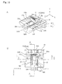
- Fig. 16 refers to the third modified embodiment.
- Fig. 16A is a perspective view and
- Fig. 16B is a plane view.
- Fig. 17 refers to the third modified embodiment.
- Fig. 17A is a sectional view taken on line A-A in Fig. 16
- Fig. 17B is a sectional view taken on line B-B in Fig. 16 .
- Fig. 18 is a perspective view of the fourth modified embodiment.
- the same reference numbers are marked to the portions corresponding to the portions of the above-mentioned example.
- the machining center is so constructed that the work fixing table 25A is moved in only the X axis direction by the lateral guide tracks 8a, 8b and that the spindle device 13 with the rotary spindle 17 is moved in the Y axis direction by the vertical guide tracks 20a, 20b on the column 2 fixed to the support/feed/turn output member 25.
- the work fixing table 25A in machining the work w such as the crank shaft supported so as to be rotatable around the horizontal axis b1, it is unnecessary to move the work w in the Z axis direction and to turn it around the line of the Y axis direction. Besides, it is possible to move the spindle device 13 in the Z axis direction due to the driving means (servomotors 33a, 33b) turning the support/feed/turn output member 25 around the line of the Y axis direction. Furthermore, the effects due to the above-mentioned construction to work the support/feed/turn output member 25 can be also obtained.
- the support/feed/turn output member 25 is not used the work fixing table 25A but used as a table for supporting the spindle device 13, and the support plate 14 is not used as a member for supporting the spindle device 13 but used as the work fixing table 25A.
Landscapes
- Engineering & Computer Science (AREA)
- Mechanical Engineering (AREA)
- Machine Tool Units (AREA)
Applications Claiming Priority (2)
| Application Number | Priority Date | Filing Date | Title |
|---|---|---|---|
| JP2007063891A JP5161468B2 (ja) | 2007-03-13 | 2007-03-13 | 工作機械 |
| PCT/JP2008/054332 WO2008111571A1 (fr) | 2007-03-13 | 2008-03-11 | Machine-outil |
Publications (3)
| Publication Number | Publication Date |
|---|---|
| EP2138265A1 true EP2138265A1 (fr) | 2009-12-30 |
| EP2138265A4 EP2138265A4 (fr) | 2011-03-16 |
| EP2138265B1 EP2138265B1 (fr) | 2012-08-08 |
Family
ID=39759506
Family Applications (1)
| Application Number | Title | Priority Date | Filing Date |
|---|---|---|---|
| EP08721748A Active EP2138265B1 (fr) | 2007-03-13 | 2008-03-11 | Machine-outil |
Country Status (7)
| Country | Link |
|---|---|
| US (1) | US8690499B2 (fr) |
| EP (1) | EP2138265B1 (fr) |
| JP (1) | JP5161468B2 (fr) |
| KR (1) | KR101430532B1 (fr) |
| CN (1) | CN101622096B (fr) |
| TW (1) | TW200920538A (fr) |
| WO (1) | WO2008111571A1 (fr) |
Cited By (1)
| Publication number | Priority date | Publication date | Assignee | Title |
|---|---|---|---|---|
| KR20230002804A (ko) * | 2020-05-18 | 2023-01-05 | 무라다기카이가부시끼가이샤 | 공작 기계 시스템 |
Families Citing this family (17)
| Publication number | Priority date | Publication date | Assignee | Title |
|---|---|---|---|---|
| JP5045410B2 (ja) * | 2007-12-10 | 2012-10-10 | 株式会社ジェイテクト | 砥石軸装置 |
| JP5562377B2 (ja) * | 2012-04-24 | 2014-07-30 | 本田技研工業株式会社 | ワーク固定装置 |
| CN102717120A (zh) * | 2012-07-03 | 2012-10-10 | 山西模范机械制造有限公司 | 曲轴钻直油孔装置 |
| CN102896549B (zh) * | 2012-08-29 | 2015-07-01 | 长城汽车股份有限公司 | 一种发动机曲轴加工上下料夹紧装置 |
| JP2014094425A (ja) * | 2012-11-09 | 2014-05-22 | Mitsui Seiki Kogyo Co Ltd | 5軸制御工作機械 |
| TW201509587A (zh) * | 2013-09-05 | 2015-03-16 | yuan-long Lai | 多軸加工機 |
| USD786323S1 (en) * | 2014-06-06 | 2017-05-09 | Hybrid Manufacturing Technologies Llc | Replaceable processing head for computer numerical control (CNC) machines |
| JP6196588B2 (ja) * | 2014-07-24 | 2017-09-13 | 株式会社スギノマシン | 送り台装置、および対象物駆動装置 |
| USD788196S1 (en) * | 2014-09-12 | 2017-05-30 | Pocket NC Company | Multi-axis machine |
| DE102016116161A1 (de) | 2016-08-30 | 2018-03-01 | Supfina Grieshaber Gmbh & Co. Kg | Werkzeugmaschine und Verfahren zur finishenden Bearbeitung von Werkstücken |
| JP6470336B2 (ja) * | 2017-03-27 | 2019-02-13 | ファナック株式会社 | 工作機械システムおよび移動方法 |
| USD861750S1 (en) * | 2018-05-02 | 2019-10-01 | Pocket NC Company | Multi-axis machine |
| CN109676200B (zh) * | 2019-01-18 | 2021-05-25 | 西安理工大学 | 一种曲面加工机床结构及其运动控制模型 |
| US11052501B1 (en) | 2020-04-13 | 2021-07-06 | The Government of the United States of America, as represented by the Secretary of Homeland Security | On-wing tool for in-situ cutting on wing-to-fuselage attachment of aircraft |
| CN112935885B (zh) * | 2021-02-10 | 2023-07-21 | 中国科学院金属研究所 | 一种高强、高脆材质类球体自动车削机床 |
| CN116890228B (zh) * | 2023-08-17 | 2025-12-02 | 重庆福伦德实业有限公司 | 新能源电机控制器高压交流组件自动组装设备 |
| CN118527690B (zh) * | 2024-07-27 | 2024-10-01 | 山西汇众兴盛电力工程有限公司 | 一种可以快速更换钻头的电力工程用台钻及其使用方法 |
Family Cites Families (14)
| Publication number | Priority date | Publication date | Assignee | Title |
|---|---|---|---|---|
| US6099217A (en) * | 1995-12-20 | 2000-08-08 | Wiegand; Alexander Konrad | Device for spatially moving a body with three to six degrees of freedom in a controlled manner |
| JPH09300149A (ja) * | 1996-05-20 | 1997-11-25 | Honda Motor Co Ltd | 作業機械 |
| JP3083776B2 (ja) | 1997-02-28 | 2000-09-04 | 株式会社不二越 | フレキシブル基準ツール |
| ES2167146B1 (es) * | 1999-04-19 | 2003-11-01 | Etxetar Sa | Maquina para taladrar agujeros de engrase en cigueñales y procedimiento correspondiente. |
| JP2001009651A (ja) * | 1999-06-30 | 2001-01-16 | Kitamura Mach Co Ltd | 工作機械 |
| DE10144678A1 (de) * | 2001-09-11 | 2003-04-03 | Emag Maschfab Gmbh | Fräs-und Bohrbearbeitungszentrum |
| JP3746730B2 (ja) * | 2002-04-24 | 2006-02-15 | 株式会社目白プレシジョン | ステージ装置 |
| JP3721563B2 (ja) * | 2002-10-28 | 2005-11-30 | ホーコス株式会社 | 工作機械におけるワーク位置決め方法 |
| JP3852050B2 (ja) | 2002-12-18 | 2006-11-29 | ホーコス株式会社 | 工作機械におけるシャフト加工方法並びに同加工装置 |
| JP4120501B2 (ja) * | 2003-07-08 | 2008-07-16 | 株式会社ジェイテクト | 4自由度パラレルロボット及びパラレルリンク加工機 |
| WO2005037477A1 (fr) * | 2003-10-10 | 2005-04-28 | Profilator Gmbh & Co. Kg | Machine-outil a systeme d'usinage par inclinaison |
| DE102004008457A1 (de) * | 2004-02-13 | 2005-09-01 | Ex-Cell-O Gmbh | Werkzeugmaschine und Verfahren zur Korrektur oder Kompensation von unterschiedlichen Werkzeuglängen in einer Werkzeugmaschine |
| JP4407934B2 (ja) | 2004-10-26 | 2010-02-03 | 株式会社不二越 | シャフト加工装置 |
| WO2007009481A1 (fr) * | 2005-07-22 | 2007-01-25 | Gebrüder Heller Maschinenfabrik Gmbh | Procede d'usinage de precision d'arbres-manivelles et centre d'usinage correspondant |
-
2007
- 2007-03-13 JP JP2007063891A patent/JP5161468B2/ja active Active
-
2008
- 2008-03-11 WO PCT/JP2008/054332 patent/WO2008111571A1/fr not_active Ceased
- 2008-03-11 CN CN2008800066552A patent/CN101622096B/zh active Active
- 2008-03-11 KR KR1020097015906A patent/KR101430532B1/ko active Active
- 2008-03-11 TW TW097108443A patent/TW200920538A/zh unknown
- 2008-03-11 EP EP08721748A patent/EP2138265B1/fr active Active
- 2008-03-11 US US12/450,111 patent/US8690499B2/en active Active
Cited By (1)
| Publication number | Priority date | Publication date | Assignee | Title |
|---|---|---|---|---|
| KR20230002804A (ko) * | 2020-05-18 | 2023-01-05 | 무라다기카이가부시끼가이샤 | 공작 기계 시스템 |
Also Published As
| Publication number | Publication date |
|---|---|
| KR101430532B1 (ko) | 2014-08-18 |
| TW200920538A (en) | 2009-05-16 |
| JP2008221413A (ja) | 2008-09-25 |
| US20100074703A1 (en) | 2010-03-25 |
| CN101622096B (zh) | 2013-05-08 |
| KR20090125751A (ko) | 2009-12-07 |
| US8690499B2 (en) | 2014-04-08 |
| JP5161468B2 (ja) | 2013-03-13 |
| WO2008111571A1 (fr) | 2008-09-18 |
| EP2138265B1 (fr) | 2012-08-08 |
| EP2138265A4 (fr) | 2011-03-16 |
| CN101622096A (zh) | 2010-01-06 |
Similar Documents
| Publication | Publication Date | Title |
|---|---|---|
| EP2138265B1 (fr) | Machine-outil | |
| US9878409B2 (en) | Machine tool for machining | |
| US5669867A (en) | Machine tool | |
| US8091191B2 (en) | Complete machining center and method | |
| EP3471915B1 (fr) | Machine pour l'usinage de pièces | |
| JP7036843B2 (ja) | 工作機械 | |
| JP5361563B2 (ja) | 旋盤 | |
| CN116638379B (zh) | 一种集成式加工机床 | |
| JP5624311B2 (ja) | 生産ラインおよび工作機械 | |
| CN211804787U (zh) | 一种数控车床 | |
| CN116475848B (zh) | 一种多工序集成式机床 | |
| CN220560901U (zh) | 一种高精度卧式加工中心 | |
| JP2000084701A (ja) | 主軸移動型工作機械におけるスプラッシュガード | |
| CN116787229A (zh) | 一种多功能车铣磨复合加工中心 | |
| WO2023162116A1 (fr) | Magasin d'outils et machine-outil | |
| JP2002011601A (ja) | 旋 盤 | |
| JP2001038503A (ja) | 加工ヘッド装置 | |
| CN117817491B (zh) | 一种压缩机阀板加工用研磨机 | |
| KR20040082433A (ko) | 가공품-베어링 스핀들을 구비한 다축 머신닝센터 | |
| CN212977667U (zh) | 一种柱面铣磨机用进给调节机构及柱面铣磨机 | |
| JP3787461B2 (ja) | 工作機械のリニアモータ駆動送り装置 | |
| CA3028843C (fr) | Machine pour l'usinage de pieces | |
| JP3236397B2 (ja) | コラム移動型横型工作機械 | |
| CN119141261A (zh) | 一种复合式多轴数控加工中心 | |
| JPH09300150A (ja) | 作業機械 |
Legal Events
| Date | Code | Title | Description |
|---|---|---|---|
| PUAI | Public reference made under article 153(3) epc to a published international application that has entered the european phase |
Free format text: ORIGINAL CODE: 0009012 |
|
| 17P | Request for examination filed |
Effective date: 20091009 |
|
| AK | Designated contracting states |
Kind code of ref document: A1 Designated state(s): AT BE BG CH CY CZ DE DK EE ES FI FR GB GR HR HU IE IS IT LI LT LU LV MC MT NL NO PL PT RO SE SI SK TR |
|
| DAX | Request for extension of the european patent (deleted) | ||
| A4 | Supplementary search report drawn up and despatched |
Effective date: 20110215 |
|
| RIC1 | Information provided on ipc code assigned before grant |
Ipc: B23Q 1/48 20060101AFI20080929BHEP Ipc: B23C 3/08 20060101ALI20110209BHEP Ipc: B23Q 1/44 20060101ALI20110209BHEP Ipc: B23C 3/06 20060101ALI20110209BHEP |
|
| 17Q | First examination report despatched |
Effective date: 20111111 |
|
| GRAP | Despatch of communication of intention to grant a patent |
Free format text: ORIGINAL CODE: EPIDOSNIGR1 |
|
| GRAS | Grant fee paid |
Free format text: ORIGINAL CODE: EPIDOSNIGR3 |
|
| GRAA | (expected) grant |
Free format text: ORIGINAL CODE: 0009210 |
|
| AK | Designated contracting states |
Kind code of ref document: B1 Designated state(s): AT BE BG CH CY CZ DE DK EE ES FI FR GB GR HR HU IE IS IT LI LT LU LV MC MT NL NO PL PT RO SE SI SK TR |
|
| REG | Reference to a national code |
Ref country code: GB Ref legal event code: FG4D |
|
| REG | Reference to a national code |
Ref country code: AT Ref legal event code: REF Ref document number: 569483 Country of ref document: AT Kind code of ref document: T Effective date: 20120815 Ref country code: CH Ref legal event code: EP |
|
| REG | Reference to a national code |
Ref country code: IE Ref legal event code: FG4D |
|
| REG | Reference to a national code |
Ref country code: DE Ref legal event code: R096 Ref document number: 602008017797 Country of ref document: DE Effective date: 20121004 |
|
| REG | Reference to a national code |
Ref country code: NL Ref legal event code: VDEP Effective date: 20120808 |
|
| REG | Reference to a national code |
Ref country code: AT Ref legal event code: MK05 Ref document number: 569483 Country of ref document: AT Kind code of ref document: T Effective date: 20120808 |
|
| REG | Reference to a national code |
Ref country code: LT Ref legal event code: MG4D Effective date: 20120808 |
|
| PG25 | Lapsed in a contracting state [announced via postgrant information from national office to epo] |
Ref country code: LT Free format text: LAPSE BECAUSE OF FAILURE TO SUBMIT A TRANSLATION OF THE DESCRIPTION OR TO PAY THE FEE WITHIN THE PRESCRIBED TIME-LIMIT Effective date: 20120808 Ref country code: FI Free format text: LAPSE BECAUSE OF FAILURE TO SUBMIT A TRANSLATION OF THE DESCRIPTION OR TO PAY THE FEE WITHIN THE PRESCRIBED TIME-LIMIT Effective date: 20120808 Ref country code: CY Free format text: LAPSE BECAUSE OF FAILURE TO SUBMIT A TRANSLATION OF THE DESCRIPTION OR TO PAY THE FEE WITHIN THE PRESCRIBED TIME-LIMIT Effective date: 20120808 Ref country code: NO Free format text: LAPSE BECAUSE OF FAILURE TO SUBMIT A TRANSLATION OF THE DESCRIPTION OR TO PAY THE FEE WITHIN THE PRESCRIBED TIME-LIMIT Effective date: 20121108 Ref country code: AT Free format text: LAPSE BECAUSE OF FAILURE TO SUBMIT A TRANSLATION OF THE DESCRIPTION OR TO PAY THE FEE WITHIN THE PRESCRIBED TIME-LIMIT Effective date: 20120808 Ref country code: HR Free format text: LAPSE BECAUSE OF FAILURE TO SUBMIT A TRANSLATION OF THE DESCRIPTION OR TO PAY THE FEE WITHIN THE PRESCRIBED TIME-LIMIT Effective date: 20120808 Ref country code: IS Free format text: LAPSE BECAUSE OF FAILURE TO SUBMIT A TRANSLATION OF THE DESCRIPTION OR TO PAY THE FEE WITHIN THE PRESCRIBED TIME-LIMIT Effective date: 20121208 |
|
| PG25 | Lapsed in a contracting state [announced via postgrant information from national office to epo] |
Ref country code: PT Free format text: LAPSE BECAUSE OF FAILURE TO SUBMIT A TRANSLATION OF THE DESCRIPTION OR TO PAY THE FEE WITHIN THE PRESCRIBED TIME-LIMIT Effective date: 20121210 Ref country code: BE Free format text: LAPSE BECAUSE OF FAILURE TO SUBMIT A TRANSLATION OF THE DESCRIPTION OR TO PAY THE FEE WITHIN THE PRESCRIBED TIME-LIMIT Effective date: 20120808 Ref country code: SI Free format text: LAPSE BECAUSE OF FAILURE TO SUBMIT A TRANSLATION OF THE DESCRIPTION OR TO PAY THE FEE WITHIN THE PRESCRIBED TIME-LIMIT Effective date: 20120808 Ref country code: LV Free format text: LAPSE BECAUSE OF FAILURE TO SUBMIT A TRANSLATION OF THE DESCRIPTION OR TO PAY THE FEE WITHIN THE PRESCRIBED TIME-LIMIT Effective date: 20120808 Ref country code: PL Free format text: LAPSE BECAUSE OF FAILURE TO SUBMIT A TRANSLATION OF THE DESCRIPTION OR TO PAY THE FEE WITHIN THE PRESCRIBED TIME-LIMIT Effective date: 20120808 Ref country code: SE Free format text: LAPSE BECAUSE OF FAILURE TO SUBMIT A TRANSLATION OF THE DESCRIPTION OR TO PAY THE FEE WITHIN THE PRESCRIBED TIME-LIMIT Effective date: 20120808 Ref country code: GR Free format text: LAPSE BECAUSE OF FAILURE TO SUBMIT A TRANSLATION OF THE DESCRIPTION OR TO PAY THE FEE WITHIN THE PRESCRIBED TIME-LIMIT Effective date: 20121109 |
|
| PG25 | Lapsed in a contracting state [announced via postgrant information from national office to epo] |
Ref country code: NL Free format text: LAPSE BECAUSE OF FAILURE TO SUBMIT A TRANSLATION OF THE DESCRIPTION OR TO PAY THE FEE WITHIN THE PRESCRIBED TIME-LIMIT Effective date: 20120808 |
|
| PG25 | Lapsed in a contracting state [announced via postgrant information from national office to epo] |
Ref country code: EE Free format text: LAPSE BECAUSE OF FAILURE TO SUBMIT A TRANSLATION OF THE DESCRIPTION OR TO PAY THE FEE WITHIN THE PRESCRIBED TIME-LIMIT Effective date: 20120808 Ref country code: ES Free format text: LAPSE BECAUSE OF FAILURE TO SUBMIT A TRANSLATION OF THE DESCRIPTION OR TO PAY THE FEE WITHIN THE PRESCRIBED TIME-LIMIT Effective date: 20121119 Ref country code: RO Free format text: LAPSE BECAUSE OF FAILURE TO SUBMIT A TRANSLATION OF THE DESCRIPTION OR TO PAY THE FEE WITHIN THE PRESCRIBED TIME-LIMIT Effective date: 20120808 Ref country code: CZ Free format text: LAPSE BECAUSE OF FAILURE TO SUBMIT A TRANSLATION OF THE DESCRIPTION OR TO PAY THE FEE WITHIN THE PRESCRIBED TIME-LIMIT Effective date: 20120808 Ref country code: DK Free format text: LAPSE BECAUSE OF FAILURE TO SUBMIT A TRANSLATION OF THE DESCRIPTION OR TO PAY THE FEE WITHIN THE PRESCRIBED TIME-LIMIT Effective date: 20120808 |
|
| PG25 | Lapsed in a contracting state [announced via postgrant information from national office to epo] |
Ref country code: IT Free format text: LAPSE BECAUSE OF FAILURE TO SUBMIT A TRANSLATION OF THE DESCRIPTION OR TO PAY THE FEE WITHIN THE PRESCRIBED TIME-LIMIT Effective date: 20120808 Ref country code: SK Free format text: LAPSE BECAUSE OF FAILURE TO SUBMIT A TRANSLATION OF THE DESCRIPTION OR TO PAY THE FEE WITHIN THE PRESCRIBED TIME-LIMIT Effective date: 20120808 |
|
| PLBE | No opposition filed within time limit |
Free format text: ORIGINAL CODE: 0009261 |
|
| STAA | Information on the status of an ep patent application or granted ep patent |
Free format text: STATUS: NO OPPOSITION FILED WITHIN TIME LIMIT |
|
| 26N | No opposition filed |
Effective date: 20130510 |
|
| PG25 | Lapsed in a contracting state [announced via postgrant information from national office to epo] |
Ref country code: BG Free format text: LAPSE BECAUSE OF FAILURE TO SUBMIT A TRANSLATION OF THE DESCRIPTION OR TO PAY THE FEE WITHIN THE PRESCRIBED TIME-LIMIT Effective date: 20121108 |
|
| REG | Reference to a national code |
Ref country code: DE Ref legal event code: R097 Ref document number: 602008017797 Country of ref document: DE Effective date: 20130510 |
|
| PG25 | Lapsed in a contracting state [announced via postgrant information from national office to epo] |
Ref country code: MC Free format text: LAPSE BECAUSE OF NON-PAYMENT OF DUE FEES Effective date: 20130331 |
|
| REG | Reference to a national code |
Ref country code: CH Ref legal event code: PL |
|
| GBPC | Gb: european patent ceased through non-payment of renewal fee |
Effective date: 20130311 |
|
| REG | Reference to a national code |
Ref country code: IE Ref legal event code: MM4A |
|
| PG25 | Lapsed in a contracting state [announced via postgrant information from national office to epo] |
Ref country code: GB Free format text: LAPSE BECAUSE OF NON-PAYMENT OF DUE FEES Effective date: 20130311 Ref country code: IE Free format text: LAPSE BECAUSE OF NON-PAYMENT OF DUE FEES Effective date: 20130311 Ref country code: LI Free format text: LAPSE BECAUSE OF NON-PAYMENT OF DUE FEES Effective date: 20130331 Ref country code: CH Free format text: LAPSE BECAUSE OF NON-PAYMENT OF DUE FEES Effective date: 20130331 |
|
| PG25 | Lapsed in a contracting state [announced via postgrant information from national office to epo] |
Ref country code: MT Free format text: LAPSE BECAUSE OF FAILURE TO SUBMIT A TRANSLATION OF THE DESCRIPTION OR TO PAY THE FEE WITHIN THE PRESCRIBED TIME-LIMIT Effective date: 20120808 |
|
| PG25 | Lapsed in a contracting state [announced via postgrant information from national office to epo] |
Ref country code: TR Free format text: LAPSE BECAUSE OF FAILURE TO SUBMIT A TRANSLATION OF THE DESCRIPTION OR TO PAY THE FEE WITHIN THE PRESCRIBED TIME-LIMIT Effective date: 20120808 |
|
| PG25 | Lapsed in a contracting state [announced via postgrant information from national office to epo] |
Ref country code: HU Free format text: LAPSE BECAUSE OF FAILURE TO SUBMIT A TRANSLATION OF THE DESCRIPTION OR TO PAY THE FEE WITHIN THE PRESCRIBED TIME-LIMIT; INVALID AB INITIO Effective date: 20080311 Ref country code: LU Free format text: LAPSE BECAUSE OF NON-PAYMENT OF DUE FEES Effective date: 20130311 |
|
| REG | Reference to a national code |
Ref country code: FR Ref legal event code: PLFP Year of fee payment: 9 |
|
| REG | Reference to a national code |
Ref country code: FR Ref legal event code: PLFP Year of fee payment: 10 |
|
| REG | Reference to a national code |
Ref country code: FR Ref legal event code: PLFP Year of fee payment: 11 |
|
| PGFP | Annual fee paid to national office [announced via postgrant information from national office to epo] |
Ref country code: DE Payment date: 20260213 Year of fee payment: 19 |
|
| PGFP | Annual fee paid to national office [announced via postgrant information from national office to epo] |
Ref country code: FR Payment date: 20260209 Year of fee payment: 19 |