EP2138273B1 - Outil rotatif disposant d'un mécanisme à cliquet manuel - Google Patents
Outil rotatif disposant d'un mécanisme à cliquet manuel Download PDFInfo
- Publication number
- EP2138273B1 EP2138273B1 EP08104538A EP08104538A EP2138273B1 EP 2138273 B1 EP2138273 B1 EP 2138273B1 EP 08104538 A EP08104538 A EP 08104538A EP 08104538 A EP08104538 A EP 08104538A EP 2138273 B1 EP2138273 B1 EP 2138273B1
- Authority
- EP
- European Patent Office
- Prior art keywords
- ratchet
- rotary tool
- tool according
- shaft
- shaft coupling
- Prior art date
- Legal status (The legal status is an assumption and is not a legal conclusion. Google has not performed a legal analysis and makes no representation as to the accuracy of the status listed.)
- Not-in-force
Links
- 230000007246 mechanism Effects 0.000 title claims description 5
- 230000008878 coupling Effects 0.000 claims description 32
- 238000010168 coupling process Methods 0.000 claims description 32
- 238000005859 coupling reaction Methods 0.000 claims description 32
- 230000005540 biological transmission Effects 0.000 claims description 6
- 230000000903 blocking effect Effects 0.000 claims description 4
- 230000001404 mediated effect Effects 0.000 description 3
- 230000009471 action Effects 0.000 description 2
- 238000010276 construction Methods 0.000 description 2
- 230000008901 benefit Effects 0.000 description 1
- 230000000295 complement effect Effects 0.000 description 1
- 238000005553 drilling Methods 0.000 description 1
Images


Classifications
-
- B—PERFORMING OPERATIONS; TRANSPORTING
- B25—HAND TOOLS; PORTABLE POWER-DRIVEN TOOLS; MANIPULATORS
- B25B—TOOLS OR BENCH DEVICES NOT OTHERWISE PROVIDED FOR, FOR FASTENING, CONNECTING, DISENGAGING OR HOLDING
- B25B21/00—Portable power-driven screw or nut setting or loosening tools; Attachments for drilling apparatus serving the same purpose
-
- B—PERFORMING OPERATIONS; TRANSPORTING
- B25—HAND TOOLS; PORTABLE POWER-DRIVEN TOOLS; MANIPULATORS
- B25B—TOOLS OR BENCH DEVICES NOT OTHERWISE PROVIDED FOR, FOR FASTENING, CONNECTING, DISENGAGING OR HOLDING
- B25B13/00—Spanners; Wrenches
- B25B13/46—Spanners; Wrenches of the ratchet type, for providing a free return stroke of the handle
- B25B13/461—Spanners; Wrenches of the ratchet type, for providing a free return stroke of the handle with concentric driving and driven member
- B25B13/462—Spanners; Wrenches of the ratchet type, for providing a free return stroke of the handle with concentric driving and driven member the ratchet parts engaging in a direction radial to the tool operating axis
- B25B13/463—Spanners; Wrenches of the ratchet type, for providing a free return stroke of the handle with concentric driving and driven member the ratchet parts engaging in a direction radial to the tool operating axis a pawl engaging an externally toothed wheel
Definitions
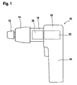
- the present invention relates to a ratchet mechanism that permits a rotary power tool to be used in a manual ratchet mode for alternatively tightening or loosening a screw.
- DE 4128651 A1 describes an electric screwdriver with a ratchet and pawl arrangement to permit manual screwdriving when the motor is inoperative.
- the tool operates in four distinct modes: forward and reverse power drill/driving modes plus forward and reverse manual ratchet modes.
- One of the four modes is conveniently selected via a rotating switch.
- the motor is electrically decoupled via movement of electrical contacts that are mechanically coupled to the rotating switch.
- a problem with this design is that if the motor is inadvertently activated while the tool is in a ratchet mode, the motor could jam and possibly be damaged. It would be useful to have a rotary power tool with the manual ratchet functionality but without the associated risks to the motor.
- a rotary power tool having a manual ratchet mechanism comprising a driveshaft driven by a motor, an output shaft, disengageable shaft coupling means for mechanically coupling the driveshaft to the output shaft, and disengageable ratchet means for blocking rotation of the output shaft unidirectionally, wherein when one of the coupling means and the ratchet means is engaged, the other one is disengaged.
- This design has the advantage that the motor is mechanically uncoupled from the output shaft when the ratchet means are operational, so that there is no possibility of damage to the motor should it be inadvertently activated.
- the shaft coupling means can be conveniently engaged or disengaged by movement axially along a rotary axis of the tool.
- a preferred or default position can be established by providing a biasing member such as a coil spring to urge the shaft coupling means to move into either the engaged or the disengaged position.
- the shaft coupling means are advantageously positioned between a transmission that modulates the output of the motor and the ratchet means. This allows adjustment means in the form of a compact adjustment collar to access both the ratchet means and the shaft coupling means.
- shaft coupling means are generally ring-shaped and at least partially surround the driveshaft and/or output shaft, then they can be conveniently positioned without separate means for positioning them within the tool. Such an arrangement also facilitates implementation of the invention into existing power tool designs without requiring extensive redesign of the internal components.
- shaft coupling means with splines for coupling with the driveshaft and/or the output shaft, rotational coupling is conveniently achieved while preserving freedom of movement in the axial direction.
- the motor is provided with a motor housing which is mechanically coupled with the ratchet means and also unitary with the tool handle, the ratchet means are conveniently utilized to provide a screwdriving function to the tool by the user.
- ratchet action can be achieved by providing a ratchet means that includes a ratchet shaft interacting with at least one locking plate.
- Means for adjusting the operational mode of the rotary tool are mechanically coupled to the shaft coupling means and the ratchet means for adjusting each into either an engaged or a disengaged position.
- the adjustment means therefore provide the basis for linking selection of the operational mode (drill/driving mode or ratchet mode) with the power state of the tool (powered or unpowered/manual).
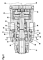
- the adjustment ring 48 is provided with two projections 50 that cooperate with cam surfaces 52 on the inner portion of the adjustment collar 14 (see Figures 4A and 4B ). Since the adjustment ring 48 is mechanically coupled with the bushing 38, the projections 50 are urged by the force of spring 46 into contact with the cam surfaces 52. The drill/driving mode illustrated in Fig. 4A . If the adjustment collar 14 is rotated in the direction of arrow 54, the cam surfaces 52 urge the adjustment ring 48 to move against the force of the spring 46, resulting in the position illustrated in Fig. 4B . Here the adjustment ring 48 has moved axially and the mechanically coupled bushing 38 has also moved axially so that it is in the position illustrated in Fig. 2 .
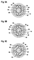
- Figure 5A illustrates that the protrusions 64 do not contact the springs 62 when the tool is operated in power drill/driving mode.
- the lock plates 58 do not contact the fins 56 of the ratchet shaft 32.
- the protrusions 64 tend to contact portions of the springs 62 so that the lock plates 58 pivot about the pins 60.
- one of the two arms 66 of each respective lock plate 58 contacts a slot 68 between the fins 56 of the ratchet shaft 32.
- the springs 62 are flexible, the lock plates 58 are able to move out of these slots 68 to permit the ratchet shaft 32 to rotate in the direction indicated by arrow 70. Rotation allows the arms 66 to return into contact with the slots 68 under the force of the springs 62. This creates the well-known ratchet sound when the ratchet shaft 32 is engaged in this fashion.
- the user may use the tool 10 much as it were simply an unpowered screwdriving device by rotating the handle 24. Since the handle 24 is coupled with the motor housing 18 and the motor housing 18 is coupled with the gearbox housing 16 and the gearbox housing 16 is rotationally coupled to the lock plates 58 via the pins 60 (see Fig. 3 ). Therefore, rotation of the handle 24 in one direction will be such that the lock plates 58 drive the ratchet shaft 32 and therefore the output shaft. Rotation in the other direction will simply cause the lock plates 58 to rotate around the ratchet shaft 32 creating a typical ratchet sound. In this way, conventional ratchet action is achieved.
- the coupling means are positioned instead between the motor pinion 26 and the planetary gear transmission 20.
- the adjustment collar 14 can in this case be enlarged so that it can still couple with both the ratchet means and the shaft coupling means.
Landscapes
- Engineering & Computer Science (AREA)
- Mechanical Engineering (AREA)
- Transmission Devices (AREA)
- Details Of Spanners, Wrenches, And Screw Drivers And Accessories (AREA)
Claims (12)
- Outil électrique rotatif disposant d'un mécanisme à cliquet manuel comprenant :un arbre d'entraînement (26, 28) entraîné par un moteur (22) ;un arbre de sortie (12, 32) ;un moyen d'accouplement d'arbre (38) pouvant être désengagé, servant à accoupler mécaniquement l'arbre d'entraînement (26, 28) à l'arbre de sortie (12, 32 ) ;un moyen d'encliquetage (32, 58) pouvant être désengagé, servant à bloquer la rotation de l'arbre de sortie (12, 32) dans une direction ;caractérisé en ce que lorsque l'un du moyen d'accouplement d'arbre (38) et du moyen d'encliquetage (56, 58, 60, 62) est engagé, l'autre est désengagé.
- Outil rotatif selon la revendication 1, caractérisé en ce que le moyen d'accouplement d'arbre (38) se déplace axialement le long d'un axe de rotation (34) de l'outil lorsqu'il se déplace d'une position engagée à une position désengagée.
- Outil rotatif selon l'une quelconque des revendications précédentes, caractérisé en ce qu'un organe de poussée (46) pousse le moyen d'accouplement d'arbre (38) à se déplacer axialement vers la position engagée ou la position désengagée.
- Outil rotatif selon l'une quelconque des revendications précédentes, caractérisé en ce qu'une transmission (20) module la sortie du moteur (22) pour transformer la vitesse et le couple d'une broche (28), et le moyen d'accouplement d'arbre (38) est positionné entre la transmission (20) et le moyen d'encliquetage (32, 58).
- Outil rotatif selon l'une quelconque des revendications précédentes, caractérisé en ce que le moyen d'accouplement d'arbre (38) est généralement de forme annulaire et entoure au moins en partie l'arbre d'entraînement (26, 28) et/ou l'arbre de sortie (12, 32).
- Outil rotatif selon l'une quelconque des revendications précédentes, caractérisé en ce que la surface interne du moyen d'accouplement d'arbre (38) est configurée avec des cannelures (40) pour s'accoupler avec l'arbre d'entraînement (26, 28) et/ou l'arbre de sortie (12, 32).
- Outil rotatif selon l'une quelconque des revendications précédentes, caractérisé en ce que le moteur (22) a un boîtier de moteur (18) qui est accouplé mécaniquement au moyen d'encliquetage (32, 58).
- Outil rotatif selon l'une quelconque des revendications précédentes, caractérisé en ce que le moyen d'encliquetage (32, 58) comprend un arbre d'encliquetage (32) qui coopère avec au moins une plaque d'encliquetage (58).
- Outil rotatif selon l'une quelconque des revendications précédentes, caractérisé en ce que des moyens (14) pour ajuster un mode fonctionnel de l'outil rotatif (10) sont accouplés mécaniquement au moyen d'accouplement d'arbre (38) et au moyen d'encliquetage (32, 58) pour ajuster chacun d'eux dans une position engagée ou désengagée.
- Outil rotatif selon la revendication 9, caractérisé en ce que les moyens (14) pour ajuster un mode fonctionnel peuvent être utilisés pour déterminer le sens du blocage unidirectionnel par le moyen d'encliquetage (32, 58, 60, 62).
- Outil rotatif selon l'une quelconque des revendications 9 et 10, caractérisé en ce que les moyens d'ajustement (14) comprennent un collier rotatif (14) ayant des saillies (64) qui viennent en contact avec les moyens d'encliquetage (58).
- Outil rotatif selon l'une quelconque des revendications 9, 10 et 11, caractérisé en ce que les moyens d'ajustement (14) comprennent un collier rotatif (14) avec une surface de came interne (52) pour ajuster le moyen d'accouplement d'arbre (38).
Priority Applications (3)
| Application Number | Priority Date | Filing Date | Title |
|---|---|---|---|
| EP08104538A EP2138273B1 (fr) | 2008-06-25 | 2008-06-25 | Outil rotatif disposant d'un mécanisme à cliquet manuel |
| US12/488,663 US8397831B2 (en) | 2008-06-25 | 2009-06-22 | Rotary tool having a manual ratchet mechanism |
| CN200910149980A CN101612726A (zh) | 2008-06-25 | 2009-06-24 | 具有手动棘轮机构的旋转工具 |
Applications Claiming Priority (1)
| Application Number | Priority Date | Filing Date | Title |
|---|---|---|---|
| EP08104538A EP2138273B1 (fr) | 2008-06-25 | 2008-06-25 | Outil rotatif disposant d'un mécanisme à cliquet manuel |
Publications (2)
| Publication Number | Publication Date |
|---|---|
| EP2138273A1 EP2138273A1 (fr) | 2009-12-30 |
| EP2138273B1 true EP2138273B1 (fr) | 2012-02-15 |
Family
ID=39996618
Family Applications (1)
| Application Number | Title | Priority Date | Filing Date |
|---|---|---|---|
| EP08104538A Not-in-force EP2138273B1 (fr) | 2008-06-25 | 2008-06-25 | Outil rotatif disposant d'un mécanisme à cliquet manuel |
Country Status (3)
| Country | Link |
|---|---|
| US (1) | US8397831B2 (fr) |
| EP (1) | EP2138273B1 (fr) |
| CN (1) | CN101612726A (fr) |
Families Citing this family (8)
| Publication number | Priority date | Publication date | Assignee | Title |
|---|---|---|---|---|
| JP5634109B2 (ja) * | 2010-04-27 | 2014-12-03 | 株式会社ミツバ | 減速機付モータ、およびサンルーフ駆動装置 |
| DK177641B1 (en) * | 2010-04-29 | 2014-01-20 | Hilti Ag | A power tool |
| US20150096413A1 (en) * | 2013-10-08 | 2015-04-09 | Colin G. Knight | Quick Release Ratchet Driver |
| CN103878725B (zh) * | 2014-04-17 | 2015-11-25 | 梁青松 | 一种加速螺丝刀 |
| DE102015111877A1 (de) * | 2015-07-22 | 2017-01-26 | Aesculap Ag | Werkzeugaufnahmeaufsatz für chirurgische Bohrmaschine mit zusätzlicher manueller Antriebseinheit und chirurgische Bohrmaschine |
| US10220493B2 (en) | 2016-09-06 | 2019-03-05 | Ingersoll-Rand Company | Spindle lock mechanism for pneumatic right-angle impact tool |
| CN115388140B (zh) * | 2022-09-13 | 2023-05-09 | 天津第一机床有限公司 | 具有准确拨齿结构的棘轮棘爪进给机构 |
| US12233516B1 (en) | 2024-08-13 | 2025-02-25 | Frederick L. Zinck | Auto-reverse ratchet mechanism and method of making and using same |
Family Cites Families (11)
| Publication number | Priority date | Publication date | Assignee | Title |
|---|---|---|---|---|
| US3120845A (en) * | 1961-02-20 | 1964-02-11 | David B Horner | Self-powered surgical drill |
| US3802518A (en) * | 1972-03-09 | 1974-04-09 | J Albert | Ratchet implement |
| US4448098A (en) * | 1982-03-10 | 1984-05-15 | Katsuyuki Totsu | Electrically driven screw-driver |
| DE4128651A1 (de) | 1991-08-29 | 1993-03-04 | Gardena Kress & Kastner Gmbh | Elektroschrauber |
| GB0008465D0 (en) * | 2000-04-07 | 2000-05-24 | Black & Decker Inc | Rotary hammer mode change mechanism |
| DE10356068A1 (de) * | 2003-12-01 | 2005-06-23 | Robert Bosch Gmbh | Handwerkzeugmaschine |
| US20060243470A1 (en) * | 2005-04-19 | 2006-11-02 | Daniel Puzio | Manual actuation of PTO-based chuck |
| US7980324B2 (en) * | 2006-02-03 | 2011-07-19 | Black & Decker Inc. | Housing and gearbox for drill or driver |
| DE102006000252A1 (de) * | 2006-05-30 | 2007-12-06 | Hilti Ag | Handwerkzeugmaschine mit Rutschkupplung |
| DE102006054190A1 (de) * | 2006-11-16 | 2008-05-21 | Robert Bosch Gmbh | Werkzeugratsche |
| US7798245B2 (en) * | 2007-11-21 | 2010-09-21 | Black & Decker Inc. | Multi-mode drill with an electronic switching arrangement |
-
2008
- 2008-06-25 EP EP08104538A patent/EP2138273B1/fr not_active Not-in-force
-
2009
- 2009-06-22 US US12/488,663 patent/US8397831B2/en not_active Expired - Fee Related
- 2009-06-24 CN CN200910149980A patent/CN101612726A/zh active Pending
Also Published As
| Publication number | Publication date |
|---|---|
| US20100071922A1 (en) | 2010-03-25 |
| EP2138273A1 (fr) | 2009-12-30 |
| CN101612726A (zh) | 2009-12-30 |
| US8397831B2 (en) | 2013-03-19 |
Similar Documents
| Publication | Publication Date | Title |
|---|---|---|
| EP2138273B1 (fr) | Outil rotatif disposant d'un mécanisme à cliquet manuel | |
| US7124839B2 (en) | Impact driver having an external mechanism which operation mode can be selectively switched between impact and drill modes | |
| US20090194305A1 (en) | Power tool | |
| EP1563960B1 (fr) | Outil à impulsion ayant un mode de percussion pouvant être activé ou désactivé | |
| US7048107B1 (en) | Driving device | |
| EP2062694B1 (fr) | Trépan à vitesses multiples et transmission à embrayage en vitesse inférieure | |
| EP1652630B1 (fr) | Outil électrique comportant des moyens pour sélectionner un mode de fonctionnement parmi plusieurs modes de fonctionnement | |
| EP2062695B1 (fr) | Sous-ensemble de transmission pour machine de forage à modes multiples | |
| US7717191B2 (en) | Multi-mode hammer drill with shift lock | |
| EP1759792B1 (fr) | Outil motorisé avec système de mandrin avec verrouillage de la broche et manchon coulissant | |
| JP2004524168A (ja) | 手持ち式工作機械 | |
| US20090126955A1 (en) | Hammer drill with hard hammer support structure | |
| EP2444205B1 (fr) | Transmission d'outil électrique | |
| JPH11285986A (ja) | 手持ち式工作機械、特に穴あけドライバ | |
| EP1932622A2 (fr) | Tournevis avec moteur et mécanisme de changement de vitesse | |
| CN103379983A (zh) | 具有减速装置的手持式工具机 | |
| EP1941974A1 (fr) | Outil manuel électrique | |
| CN100515692C (zh) | 配有安全联接器的冲击锤和/或冲击钻 | |
| US6832500B1 (en) | Electric door lock | |
| WO2001051232A1 (fr) | Dispositif a gachette et embrayage pour outils mecaniques | |
| WO2005085677A1 (fr) | Unite de sortie en rotation | |
| EP1599318B1 (fr) | Outil electrique a inverseur de marche actionne par une couronne de manoeuvre externe | |
| SE529928C2 (sv) | Låsanordning för portabelt verktyg | |
| JP2009536105A (ja) | 二重フリーホイール駆動軸ロックを備えた携帯型動力工具 | |
| JP2004082289A (ja) | 振動ドリルドライバ |
Legal Events
| Date | Code | Title | Description |
|---|---|---|---|
| PUAI | Public reference made under article 153(3) epc to a published international application that has entered the european phase |
Free format text: ORIGINAL CODE: 0009012 |
|
| AK | Designated contracting states |
Kind code of ref document: A1 Designated state(s): AT BE BG CH CY CZ DE DK EE ES FI FR GB GR HR HU IE IS IT LI LT LU LV MC MT NL NO PL PT RO SE SI SK TR |
|
| AX | Request for extension of the european patent |
Extension state: AL BA MK RS |
|
| 17P | Request for examination filed |
Effective date: 20100630 |
|
| AKX | Designation fees paid |
Designated state(s): DE FR GB |
|
| GRAP | Despatch of communication of intention to grant a patent |
Free format text: ORIGINAL CODE: EPIDOSNIGR1 |
|
| GRAS | Grant fee paid |
Free format text: ORIGINAL CODE: EPIDOSNIGR3 |
|
| GRAA | (expected) grant |
Free format text: ORIGINAL CODE: 0009210 |
|
| AK | Designated contracting states |
Kind code of ref document: B1 Designated state(s): DE FR GB |
|
| REG | Reference to a national code |
Ref country code: GB Ref legal event code: FG4D |
|
| REG | Reference to a national code |
Ref country code: DE Ref legal event code: R096 Ref document number: 602008013418 Country of ref document: DE Effective date: 20120412 |
|
| PGFP | Annual fee paid to national office [announced via postgrant information from national office to epo] |
Ref country code: GB Payment date: 20120621 Year of fee payment: 5 |
|
| PLBE | No opposition filed within time limit |
Free format text: ORIGINAL CODE: 0009261 |
|
| STAA | Information on the status of an ep patent application or granted ep patent |
Free format text: STATUS: NO OPPOSITION FILED WITHIN TIME LIMIT |
|
| PGFP | Annual fee paid to national office [announced via postgrant information from national office to epo] |
Ref country code: DE Payment date: 20120822 Year of fee payment: 5 |
|
| 26N | No opposition filed |
Effective date: 20121116 |
|
| REG | Reference to a national code |
Ref country code: DE Ref legal event code: R097 Ref document number: 602008013418 Country of ref document: DE Effective date: 20121116 |
|
| PGFP | Annual fee paid to national office [announced via postgrant information from national office to epo] |
Ref country code: FR Payment date: 20130703 Year of fee payment: 6 |
|
| GBPC | Gb: european patent ceased through non-payment of renewal fee |
Effective date: 20130625 |
|
| REG | Reference to a national code |
Ref country code: DE Ref legal event code: R119 Ref document number: 602008013418 Country of ref document: DE Effective date: 20140101 |
|
| PG25 | Lapsed in a contracting state [announced via postgrant information from national office to epo] |
Ref country code: GB Free format text: LAPSE BECAUSE OF NON-PAYMENT OF DUE FEES Effective date: 20130625 Ref country code: DE Free format text: LAPSE BECAUSE OF NON-PAYMENT OF DUE FEES Effective date: 20140101 |
|
| REG | Reference to a national code |
Ref country code: FR Ref legal event code: ST Effective date: 20150227 |
|
| PG25 | Lapsed in a contracting state [announced via postgrant information from national office to epo] |
Ref country code: FR Free format text: LAPSE BECAUSE OF NON-PAYMENT OF DUE FEES Effective date: 20140630 |