EP2138352A1 - Système optique et procédé de reconnaissance de voilage optique dans un véhicule - Google Patents
Système optique et procédé de reconnaissance de voilage optique dans un véhicule Download PDFInfo
- Publication number
- EP2138352A1 EP2138352A1 EP08158859A EP08158859A EP2138352A1 EP 2138352 A1 EP2138352 A1 EP 2138352A1 EP 08158859 A EP08158859 A EP 08158859A EP 08158859 A EP08158859 A EP 08158859A EP 2138352 A1 EP2138352 A1 EP 2138352A1
- Authority
- EP
- European Patent Office
- Prior art keywords
- optical system
- optical
- image
- obfuscation
- vehicle
- Prior art date
- Legal status (The legal status is an assumption and is not a legal conclusion. Google has not performed a legal analysis and makes no representation as to the accuracy of the status listed.)
- Granted
Links
Images


Classifications
-
- B—PERFORMING OPERATIONS; TRANSPORTING
- B60—VEHICLES IN GENERAL
- B60R—VEHICLES, VEHICLE FITTINGS, OR VEHICLE PARTS, NOT OTHERWISE PROVIDED FOR
- B60R1/00—Optical viewing arrangements; Real-time viewing arrangements for drivers or passengers using optical image capturing systems, e.g. cameras or video systems specially adapted for use in or on vehicles
- B60R1/02—Rear-view mirror arrangements
- B60R1/06—Rear-view mirror arrangements mounted on vehicle exterior
- B60R1/0602—Rear-view mirror arrangements mounted on vehicle exterior comprising means for cleaning or deicing
-
- G—PHYSICS
- G06—COMPUTING OR CALCULATING; COUNTING
- G06T—IMAGE DATA PROCESSING OR GENERATION, IN GENERAL
- G06T7/00—Image analysis
- G06T7/0002—Inspection of images, e.g. flaw detection
- G06T7/0004—Industrial image inspection
- G06T7/001—Industrial image inspection using an image reference approach
-
- G—PHYSICS
- G06—COMPUTING OR CALCULATING; COUNTING
- G06T—IMAGE DATA PROCESSING OR GENERATION, IN GENERAL
- G06T7/00—Image analysis
- G06T7/97—Determining parameters from multiple pictures
-
- G—PHYSICS
- G06—COMPUTING OR CALCULATING; COUNTING
- G06T—IMAGE DATA PROCESSING OR GENERATION, IN GENERAL
- G06T2207/00—Indexing scheme for image analysis or image enhancement
- G06T2207/10—Image acquisition modality
- G06T2207/10016—Video; Image sequence
-
- G—PHYSICS
- G06—COMPUTING OR CALCULATING; COUNTING
- G06T—IMAGE DATA PROCESSING OR GENERATION, IN GENERAL
- G06T2207/00—Indexing scheme for image analysis or image enhancement
- G06T2207/30—Subject of image; Context of image processing
- G06T2207/30248—Vehicle exterior or interior
- G06T2207/30252—Vehicle exterior; Vicinity of vehicle
Definitions
- the invention relates to an optical system with the possibility of obscuring the optics to recognize, and optionally initiate measures that warn either the driver and / or the activation of a heater that reduces the detected obfuscation of the image.
- New assistance functions are being continuously developed for use in a driver assistance system.
- One of these new assistance functions designed to assist the driver in changing lanes is called the LCA (Lane Change Assistant).
- the environment of the Vehicle in particular its rear and side area, in turn monitored with a suitable environment sensor.
- sensors based on radar, lidar or image sensors can be used as environmental sensors.
- This assistance function warns the driver of dangerous overtaking and lane change procedures.
- a critical situation is indicated to the driver, for example by an audible, visual or haptic warning, or by a combination of such warnings.
- An intended lane change of the own vehicle is recognized by the driver assistance system as a rule by the fact that the driver sets the turn signal when initiating the lane change.
- the basic prerequisite for the flawless use of the optical sensors that are used for image acquisition is that the optics exposed to the environmental conditions ensure a reliable imaging of the environment. Especially in automotive applications, the sensors are exposed to normal environmental conditions.
- the mounting situation of, for example, a blind spot monitoring system on the exterior mirror can not prevent objects obscuring the camera lens. Due to the air currents and chaotic turbulences around the vehicle, dirt particles settle on the optics. Splashing water and rain cause dripping on the lens. Temperature change and different humidity is the cause of fogging. In cold zones ice can also form on the lenses
- the cause of the optical scattering are fittings, which usually consist of water, such as dew and frost, or dirt. Dirt is composed of other materials such as oils, fats, or non-transparent solids, which may also be dissolved in the water.
- the object of the present invention is to detect and identify these masking and obfuscation conditions and to initiate measures either to warn the driver and / or to at least partially remove the obstruction by means of a heater.
- WO2005 / 033772 describes a camera sensor whose cover is heated with a resistance heater.
- the inventive method for detecting the optical concealment of the sensor makes use of at least two sensors. This increases the redundancy of a statement about the degree of obfuscation and about the quality of obfuscation. Especially for the automotive security systems, this increase in security in image recognition is important.
- the use of the same image recognition sensor as for obfuscation detection reduces the number of components required and therefore can keep the size of the component low and the cost low.
- the obfuscation from the actual image is detected by an algorithm which determines the gray value distribution in the image.
- no additional sensor is necessary.
- Another advantage results from the fact that a complete coverage of a sensor can be determined very easily by comparing the images of several sensors.
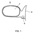
- FIG. 1 shows an exemplary vehicle exterior mirror 6,
- the rearview mirror assembly consists of a mirror head and a mirror base.
- the mirror itself is arranged in the mirror head.
- the mirror base is flush with the vehicle contour 8.
- An optical sensor 9 is attached to in the rearview mirror assembly, in this embodiment in or on the mirror base.
- the optical sensor is any type of sensor that can be used for image acquisition.
- the sensor is installed in an embodiment not shown in or on the mirror head.
- FIG. 2 schematically shows the structure of the optical sensor system.
- An optical lens 12 is connected upstream of a sensor chip 10.
- This optical chip is connected to an image data link 21 with an image processor 17. This communicates bidirectionally with a communication controller.
- This Communication controller 18 establishes the connection to further controllers in the vehicle via the vehicle bus, for example a LIN bus, CAN bus or Flexiray or via a special LVDS (Low Voltage Differential Signaling) communication line.
- the output unit 20 is addressed via the communication controller, either directly as in the example or via the vehicle bus system.
- the image processor in turn accesses the sensor chip via the sensor control connection.
- the output unit 20 may be a simple LED indicating degradation of the optics or a warning in a display.
- the position and type of display can be realized in a variety of ways that a person skilled in the art would provide for such a display.
- FIG. 2 sketched system is used on both sides of the vehicle in the rearview mirrors.
- the principle for each optical sensor can be realized regardless of its position on the vehicle.
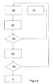
- Step 3 detects the fact that there is a fog or a disturbance.
- a positive decision on obfuscation step 4 is initiated, which means either an indication of malfunction and / or the switching on a heater. The process is then started again from step 1. If the decision of the fault detection 3 is negative, the display and / or the heating function is terminated again and the process starts again from step 1 on.
- the critical point in this method is Fault Detection 3.
- a basic algorithm in the image processor evaluates the contrast within the camera image and determines the gradient to determine a measure of the change in contrast. The simplest case represents a surface-limited contamination.
- algorithms within the image search for gradients with a gradual progression of the gray value distribution. If there is a "sudden" step in the picture and a transition of a stochastic gray scale distribution to a large gray value field with a homogeneous contiguous gray value, it can be concluded that there is a contamination on the lens.
- a concealment of the image may be a decision based on the evaluation of only one image sensor, but also in this case the comparison with a second image of a second image sensor gives greater security in the decision.
- a "blocked camera algorithm” is used, which detects the image data of the further camera sensor as blocked and informs the driver about the blockage. The gradient of the gray values in the image is determined. This state can be calculated almost without “external help" from the available image information.
- a method of inter-camera communication is introduced, which makes it possible to evaluate at least coarse brightness information from another on-vehicle camera system.
- the camera systems exchange information about the operating mode day / night mode by measuring the brightness.
- the information of the other camera system is included in the evaluation.
- the additional reference makes a more reliable statement possible. From this additionally available information further concealment and obfuscation conditions can be derived.
- total obfuscation Another special case is total obfuscation.
- total occlusion the external help of the other camera system is added to the evaluation.
- semi-transparent occultation I am dealing with the most complex form of contamination that must be recognized. This is the case when the optics of the sensor system have fogged or a frost layer on the lens.
- the camera system uses the information from the other camera in order to additionally determine the cause of the contrast poverty via its operating state.
- FIG. 4 shows a course of procedure for the determination of a concealment. The entire procedure corresponds to step 3 FIG. 2 ,
- Process 52 represents the greyscale detection which first provides a measure of the brightness so as to determine day or night.
- the gray value detection 52 is connected to the gray value comparison 53 in the next step. In this step it is decided if the values of the second image acquisition have to be used. If the obfuscation is present, the information of the other sensor is used.
- the counter 54 is driven and set high by one value. The image analysis starts again. As long as the obfuscation remains or increases, the increment of the counter is counted up to a threshold. Upon reaching the threshold in step 55, the warning function of the display is activated. Alternatively or simultaneously, a heater is activated The counter 54 is not reset to zero with the activation of the measures but counted back so that the action can take place over time. The counter 54 is counted down to a second threshold.
- the Lichtaustrittsrome optical sensors are provided with a heater. Fittings made of pure water without mixed dirt particles are most easily removed by evaporating or sublimating the water under the influence of heat.
- fittings appear at the most exposed element, which is the interface of the optical system to the environment. In many cases, this is the lens or the outermost lens. There prevail the largest temperature differences.
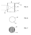
- FIG. 5 schematically shows an optical sensor 9 with an optical lens 12 and a sensor chip 10.
- the sensor chip sits on a board 11 and is connected via electrical connections 13 to the vehicle.
- the optical element can be heated, it is advantageous to provide its entire surface with a heating resistor.
- the optical function of this Elements is not affected if this heating resistor is designed to be transparent for the wavelength range of the light in which the unimpeded light transmission is necessary for the respective application.
- this heating resistor is designed to be transparent for the wavelength range of the light in which the unimpeded light transmission is necessary for the respective application.
- ITO indium tin oxide, tin-doped indium oxide
- SnO tin oxide
- ZnO: Al aluminum-doped zinc oxide
- FTO fluorine-doped tin oxide
- the heating resistor is applied as a flat element on the entire surface necessary for the function of the optical element in the form of a coating.
- a primer or primer layer can be applied beforehand.
- this can be a material of the optical element, for example of silicon dioxide (SiO 2 ).
- the feeding of the electrical energy into the heating resistor can be done by means of a conductor track, which, in the same way as heating cables to vehicle window heaters, is applied to the optical element to be heated.
- a conductor track which, in the same way as heating cables to vehicle window heaters, is applied to the optical element to be heated.
- FIG. 7 an embodiment is shown showing heating coils on the optical element.
- the heating resistor can be applied both inside and outside on the outermost optical element.
- the contacting can be done by means of a spring contact or a spring contact strip made of metal. Another possibility is the contacting by means of conductive deformable plastics.
- the contact can by means of soldered contacts such. As solder tails or soldered leads done. So that contacting elements can be soldered on, suitable metal layers such as copper (Cu), for example, are applied to the surface of the heating resistor beforehand.
- Cu copper
- the supply line can be made from the inside such that the necessary adhesion, passivation and protective layers around the edge of the optical element from the side facing away from the external environment (inner side) on the outer Be guided side.
- the contact can be guided by means of a conductor track from the inside to the outside. So that it is protected, the actual heating resistor is contacted in the region of sealing or enclosing elements of the heatable optical element.
- a passivation layer may be applied depending on the material used to avoid corrosion. This can for example consist of silicon dioxide (SiO 2 ) or silicon nitride (Si 3 N 4 ). Both the passivation layers and the heating resistor layer may be part of an antireflective coating. An antireflection coating can also be applied additionally to the heat conductor layer if the layer thickness of the heating resistor does not prohibit its use as part of an antireflection coating. The antireflection coating may consist, for example, of titanium dioxide (TiO 2 ), silicon dioxide (SiO 2 ) or silicon nitride (Si 3 N 4 ).
- a coating for increasing the scratch resistance can be applied. This is appropriate when the heater is applied to the outside of a plastic lens.
- the materials used for the primer layer, the heating layer and the anti-reflection layer (s) are already relatively hard on their own, they simultaneously constitute a scratch-resistant layer.
- a hydrophilic coating is applied to the optical element on its outermost side. This causes not single drops, but a uniformly distributed moisture film on the surface. This film prevents dirt dissolved in the water or mixed with water from drying out on the surface, but, following gravity, drains the water into the edge area and is removed with the water draining off
- a hydrophobic coating is applied to the optical element on its outermost side. This causes individual drops that lie on the surface have a very small contact surface to this. This film prevents dirt dissolved in the water or mixed with water from drying out on the surface but, following gravity, drains into the edge area and is removed with the water draining off.
Landscapes
- Engineering & Computer Science (AREA)
- Computer Vision & Pattern Recognition (AREA)
- Physics & Mathematics (AREA)
- General Physics & Mathematics (AREA)
- Theoretical Computer Science (AREA)
- Multimedia (AREA)
- Mechanical Engineering (AREA)
- Quality & Reliability (AREA)
- Traffic Control Systems (AREA)
- Studio Devices (AREA)
Priority Applications (3)
| Application Number | Priority Date | Filing Date | Title |
|---|---|---|---|
| DE502008000539T DE502008000539D1 (de) | 2008-06-24 | 2008-06-24 | Optisches System und Verfahren zur Erkennung von optischer Verschleierung in einem Fahrzeug |
| EP08158859A EP2138352B1 (fr) | 2008-06-24 | 2008-06-24 | Système optique et procédé de reconnaissance de voilage optique dans un véhicule |
| US12/489,952 US8395514B2 (en) | 2008-06-24 | 2009-06-23 | Optical system and method for detecting optical system obscuration in a vehicle |
Applications Claiming Priority (1)
| Application Number | Priority Date | Filing Date | Title |
|---|---|---|---|
| EP08158859A EP2138352B1 (fr) | 2008-06-24 | 2008-06-24 | Système optique et procédé de reconnaissance de voilage optique dans un véhicule |
Publications (2)
| Publication Number | Publication Date |
|---|---|
| EP2138352A1 true EP2138352A1 (fr) | 2009-12-30 |
| EP2138352B1 EP2138352B1 (fr) | 2010-04-07 |
Family
ID=40184872
Family Applications (1)
| Application Number | Title | Priority Date | Filing Date |
|---|---|---|---|
| EP08158859A Active EP2138352B1 (fr) | 2008-06-24 | 2008-06-24 | Système optique et procédé de reconnaissance de voilage optique dans un véhicule |
Country Status (3)
| Country | Link |
|---|---|
| US (1) | US8395514B2 (fr) |
| EP (1) | EP2138352B1 (fr) |
| DE (1) | DE502008000539D1 (fr) |
Cited By (3)
| Publication number | Priority date | Publication date | Assignee | Title |
|---|---|---|---|---|
| DE102018207803A1 (de) * | 2018-05-17 | 2019-11-21 | Bayerische Motoren Werke Aktiengesellschaft | Vorausschauender Scheibenwischer |
| DE102019109748A1 (de) * | 2019-04-12 | 2020-10-15 | Connaught Electronics Ltd. | Bildverarbeitungsverfahren |
| DE102022109081A1 (de) | 2022-04-13 | 2023-10-19 | Schaeffler Technologies AG & Co. KG | Vorrichtung zur zumindest teilweisen Entfernung eines zumindest partiellen Belages von der Oberfläche einer Sensoreinrichtung und Fahrgestell für ein Kraftfahrzeug |
Families Citing this family (51)
| Publication number | Priority date | Publication date | Assignee | Title |
|---|---|---|---|---|
| US10703299B2 (en) | 2010-04-19 | 2020-07-07 | SMR Patents S.à.r.l. | Rear view mirror simulation |
| US10800329B2 (en) | 2010-04-19 | 2020-10-13 | SMR Patents S.à.r.l. | Rear view mirror simulation |
| DE102011122457A1 (de) | 2011-12-24 | 2013-06-27 | Connaught Electronics Ltd. | Verfahren zum Betreiben einer Kameraanordnung, Kameraanordnung und Fahrerassistenzsystem |
| DE102018116011B4 (de) | 2018-07-02 | 2020-07-02 | Motherson Innovations Company Limited | Dichtungsmittel, Basisanordnung mit einem solchen Dichtungsmittel und Rückblickvorrichtung mit einer solchen Basisanordnung |
| DE102018116008B4 (de) | 2018-07-02 | 2020-07-02 | Motherson Innovations Company Limited | Basisanordnung mit Rückblickvorrichtung |
| EP3632748B1 (fr) | 2018-10-04 | 2022-05-18 | Motherson Innovations Company Limited | Ensemble de vue arrière et véhicule comportant un tel ensemble de vue arrière |
| EP2871629B1 (fr) * | 2012-07-03 | 2018-08-15 | Clarion Co., Ltd. | Dispositif de reconnaissance de l'environnement monté dans un véhicule |
| DE102014201161A1 (de) * | 2014-01-23 | 2015-07-23 | Robert Bosch Gmbh | Verfahren und Vorrichtung zum Ermitteln eines blinden Bereichs einer Kamera |
| US10079640B1 (en) * | 2014-07-31 | 2018-09-18 | Collinear Networks, Inc. | Window heater with reduced wavefront distortion |
| FR3039114B1 (fr) * | 2015-07-22 | 2017-07-28 | Valeo Systemes Dessuyage | Dispositif de nettoyage d'un capteur pour vehicule automobile |
| CN106564437A (zh) * | 2016-10-31 | 2017-04-19 | 九江学院 | 一种智能汽车后视装置 |
| US11026686B2 (en) | 2016-11-08 | 2021-06-08 | Covidien Lp | Structure for attaching buttress to anvil and/or cartridge of surgical stapling instrument |
| US10368868B2 (en) | 2017-03-09 | 2019-08-06 | Covidien Lp | Structure for attaching buttress material to anvil and cartridge of surgical stapling instrument |
| US20180272945A1 (en) * | 2017-03-24 | 2018-09-27 | Ford Global Technologies, Llc | Condensation detection for vehicle surfaces via ambient light |
| US10144356B2 (en) * | 2017-03-24 | 2018-12-04 | Ford Global Technologies, Llc | Condensation detection for vehicle surfaces via light transmitters and receivers |
| US10759348B2 (en) | 2017-03-31 | 2020-09-01 | Motherson Innovations Company Limited | Rear view assembly for a motor vehicle with interchangeable approach lamp |
| DE102017130246B4 (de) | 2017-12-15 | 2024-06-06 | Motherson Innovations Company Limited | Rückblickvorrichtung und Kraftfahrzeug |
| EP4234333B1 (fr) | 2017-04-20 | 2025-05-28 | Motherson Innovations Company Ltd. | Lampe d'approche et lampe à logo combinées |
| WO2018206484A1 (fr) | 2017-05-08 | 2018-11-15 | SMR Patents S.à.r.l. | Unité d'éclairage et d'enregistrement d'images pouvant être déplacée pour un véhicule automobile |
| DE102017117024B4 (de) | 2017-07-27 | 2021-01-21 | SMR Patents S.à.r.l. | Kameraanordnung und Kraftfahrzeug mit Kameraanordnung |
| DE102017109872B4 (de) | 2017-05-08 | 2023-05-11 | SMR Patents S.à.r.l. | Beleuchtungs- und Bildaufnahme-Einheit für ein Kraftfahrzeug |
| EP3406488B1 (fr) | 2017-05-24 | 2020-07-01 | SMR Patents S.à.r.l. | Rétroviseur externe à tête mobile |
| EP3409537B1 (fr) | 2017-05-30 | 2019-07-10 | SMR Patents S.à.r.l. | Section de tête pour un dispositif de vision arrière |
| DE102017112915B4 (de) | 2017-06-12 | 2021-07-01 | SMR Patents S.à.r.l. | Außenrückblickvorrichtung mit abnehmbarem Kopf und Fahrzeug mit solch einer Vorrichtung |
| US11370359B2 (en) | 2017-06-30 | 2022-06-28 | SMR Patents S.à.r.l. | Rearview device with moveable head assembly and vehicle therewith |
| JP7002573B2 (ja) | 2017-06-30 | 2022-01-20 | エスエムアール・パテンツ・ソシエテ・ア・レスポンサビリテ・リミテ | 可動ヘッド組立体を備えた後方観察デバイスおよびそれを備えた車両 |
| EP3442828B1 (fr) | 2017-06-30 | 2022-01-05 | SMR Patents Sarl | Ensemble, procédé d'assemblage d'un tel ensemble, procédé de démontage d'un tel ensemble, rétroviseur extérieur avec un tel ensemble et véhicule automobile avec un tel rétroviseur |
| DE102017117032B4 (de) | 2017-07-27 | 2021-01-28 | SMR Patents S.à.r.l. | Kameraanordnung und Kraftfahrzeug mit Kameraanordnung |
| DE102017117153B4 (de) | 2017-07-28 | 2021-06-02 | SMR Patents S.à.r.l. | Kameravorrichtung, Rückblickvorrichtung und Kraftfahrzeug |
| DE102017119542A1 (de) | 2017-08-25 | 2019-02-28 | SMR Patents S.à.r.l. | Rückblickvorrichtung und Fahrzeug mit einer solchen Rückblickvorrichtung |
| EP3451279B8 (fr) | 2017-08-30 | 2025-05-14 | SMR Patents S.à.r.l. | Simulation de rétroviseur arrière |
| WO2019052772A1 (fr) | 2017-09-14 | 2019-03-21 | Motherson Innovations Company Ltd. | Système modulaire et dispositif de rétroviseur ainsi que véhicule automobile doté d'un tel système modulaire |
| DE102017121376B4 (de) | 2017-09-14 | 2021-01-14 | Motherson Innovations Company Limited | Verfahren zum Betreiben eines Kraftfahrzeugs mit zumindest einer Außenkamera sowie Kraftfahrzeug mit zumindest einer Außenkamera |
| DE102017121737B4 (de) | 2017-09-19 | 2019-09-12 | SMR Patents S.à.r.l. | Sicherungsring, Rückblickvorrichtung und Fahrzeug |
| US10755495B1 (en) * | 2017-09-25 | 2020-08-25 | State Farm Mutual Automobile Insurance Company | Technology for detecting onboard sensor tampering |
| US10053059B1 (en) | 2017-10-04 | 2018-08-21 | Ford Global Technologies, Llc | Detection and identification of opaqueness of vehicle windows |
| US10836318B2 (en) | 2017-10-16 | 2020-11-17 | SMR Patents S.à.r.l. | Logo lamp assembly and method of using same |
| CN111448102B (zh) | 2017-11-01 | 2023-11-24 | Smr专利有限公司 | 外部后视设备和车辆 |
| EP3480062B1 (fr) | 2017-11-01 | 2020-09-09 | SMR Patents S.à.r.l. | Dispositif de rétroviseur comportant un ensemble à tête mobile |
| DE102017125757B4 (de) | 2017-11-03 | 2019-11-28 | SMR Patents S.à.r.l. | Rückblickvorrichtung und Kraftfahrzeug |
| DE102017126404B3 (de) | 2017-11-10 | 2019-02-07 | Motherson Innovations Company Limited | Rückblickvorrichtung und Fahrzeug mit solcher Rückblickvorrichtung |
| DE102017129186B4 (de) | 2017-12-07 | 2021-07-01 | Motherson Innovations Company Limited | Rückblickvorrichtung für ein Kraftfahrzeug, Montageverfahren dafür und Kraftfahrzeug mit einer Rückblickvorrichtung |
| DE102018121580B4 (de) | 2018-09-04 | 2024-06-06 | Motherson Innovations Company Limited | Beleuchtungsvorrichtung und Rückblickvorrichtung damit |
| WO2019115746A1 (fr) | 2017-12-15 | 2019-06-20 | Motherson Innovations Company Ltd. | Dispositif d'éclairage, dispositif de rétroviseur et véhicule à moteur |
| DE102017130347A1 (de) | 2017-12-18 | 2019-06-19 | Motherson Innovations Company Limited | Leuchte sowie Rückblickvorrichtung und Kraftfahrzeug mit Leuchte |
| US11518400B2 (en) | 2018-01-09 | 2022-12-06 | Motherson Innovations Company Limited | Method and device for detecting a roadside object |
| EP3726473A1 (fr) | 2019-04-18 | 2020-10-21 | SMR Patents S.à.r.l. | Procédé de simulation de dispositif de rétroviseur |
| EP4180273B1 (fr) | 2021-11-11 | 2025-04-02 | SMR Patents S.à.r.l. | Ensemble, procédé de montage et de démontage d'un tel ensemble, dispositif de rétroviseur extérieur et véhicule doté d'un tel ensemble |
| DE102021129655A1 (de) | 2021-11-15 | 2023-05-17 | Bayerische Motoren Werke Aktiengesellschaft | Verfahren zum Betreiben einer Radarsensoreinheit, Radarsensoreinheit sowie Kraftfahrzeug |
| DE102022106967B4 (de) | 2022-03-24 | 2024-01-25 | Bayerische Motoren Werke Aktiengesellschaft | Verfahren zum Betreiben einer Radarsensoreinheit, Radarsensoreinheit sowie Kraftfahrzeug |
| DE102022132572A1 (de) | 2022-12-07 | 2024-06-13 | Audi Aktiengesellschaft | System zum Reinigen eines Bildschirms |
Citations (5)
| Publication number | Priority date | Publication date | Assignee | Title |
|---|---|---|---|---|
| EP0717446A2 (fr) | 1994-12-14 | 1996-06-19 | Eastman Kodak Company | Panneau d'affichage électroluminescent utilisant des transistors à couches minces et des films organiques électroluminescents |
| EP1418089A2 (fr) * | 2002-11-05 | 2004-05-12 | C.R.F. Società Consortile per Azioni | Système optique multifonctionel intégré avec une matrice CMOS ou CCD |
| WO2005033772A1 (fr) | 2003-09-02 | 2005-04-14 | Valeo Schalter Und Sensoren Gmbh | Module camera dote d'une plaque de couverture chauffante |
| DE202005018498U1 (de) * | 2005-11-26 | 2006-03-02 | E.T.R. Elektronik Technologie Rump Gmbh | System zur Feststellung der Betauung von Oberflächen mit automatischer bedarfsgerechter Heizungssteuerung |
| DE202007007112U1 (de) * | 2006-05-19 | 2007-10-18 | Chen, Mei-Kuei, Tucheng City | Automatische Spiegelenteisungsvorrichtung |
Family Cites Families (9)
| Publication number | Priority date | Publication date | Assignee | Title |
|---|---|---|---|---|
| CH665915A5 (de) * | 1981-11-13 | 1988-06-15 | Paul Kovacs | Vorrichtung zur ueberwachung der eisbildung. |
| US5416476A (en) * | 1991-11-29 | 1995-05-16 | Rendon; Edward | Method and system for detecting potential icy conditions on roads |
| US6166645A (en) * | 1999-01-13 | 2000-12-26 | Blaney; Kevin | Road surface friction detector and method for vehicles |
| US6429933B1 (en) * | 1999-03-12 | 2002-08-06 | Valeo Electrical Systems, Inc. | Method of image processing for off the glass rain sensing |
| US7050949B2 (en) * | 1999-12-28 | 2006-05-23 | Niles Co., Ltd. | Signal processing method and device |
| DE10012004A1 (de) * | 2000-03-11 | 2001-09-27 | Bosch Gmbh Robert | Einrichtung zum Sauberhalten optischer Elemente in Kraftfahrzeugen, insbesondere von Sensor- oder Kamera-Abdeckungen |
| AU2004219513B2 (en) * | 2003-03-14 | 2009-08-27 | Liwas Aps | A device for detection of road surface condition |
| JP3925488B2 (ja) * | 2003-11-11 | 2007-06-06 | 日産自動車株式会社 | 車両用画像処理装置 |
| US20100020170A1 (en) * | 2008-07-24 | 2010-01-28 | Higgins-Luthman Michael J | Vehicle Imaging System |
-
2008
- 2008-06-24 DE DE502008000539T patent/DE502008000539D1/de active Active
- 2008-06-24 EP EP08158859A patent/EP2138352B1/fr active Active
-
2009
- 2009-06-23 US US12/489,952 patent/US8395514B2/en active Active
Patent Citations (5)
| Publication number | Priority date | Publication date | Assignee | Title |
|---|---|---|---|---|
| EP0717446A2 (fr) | 1994-12-14 | 1996-06-19 | Eastman Kodak Company | Panneau d'affichage électroluminescent utilisant des transistors à couches minces et des films organiques électroluminescents |
| EP1418089A2 (fr) * | 2002-11-05 | 2004-05-12 | C.R.F. Società Consortile per Azioni | Système optique multifonctionel intégré avec une matrice CMOS ou CCD |
| WO2005033772A1 (fr) | 2003-09-02 | 2005-04-14 | Valeo Schalter Und Sensoren Gmbh | Module camera dote d'une plaque de couverture chauffante |
| DE202005018498U1 (de) * | 2005-11-26 | 2006-03-02 | E.T.R. Elektronik Technologie Rump Gmbh | System zur Feststellung der Betauung von Oberflächen mit automatischer bedarfsgerechter Heizungssteuerung |
| DE202007007112U1 (de) * | 2006-05-19 | 2007-10-18 | Chen, Mei-Kuei, Tucheng City | Automatische Spiegelenteisungsvorrichtung |
Cited By (6)
| Publication number | Priority date | Publication date | Assignee | Title |
|---|---|---|---|---|
| DE102018207803A1 (de) * | 2018-05-17 | 2019-11-21 | Bayerische Motoren Werke Aktiengesellschaft | Vorausschauender Scheibenwischer |
| DE102019109748A1 (de) * | 2019-04-12 | 2020-10-15 | Connaught Electronics Ltd. | Bildverarbeitungsverfahren |
| DE102019109748B4 (de) | 2019-04-12 | 2024-10-02 | Connaught Electronics Ltd. | Bildverarbeitungsverfahren in einem Bilderfassungssystem eines Fahrzeugs betreibbar sowie Bilderfassungssystem zum Durchführen des Verfahren sowie Fahrzeug und Nichttransitorisches Computerprogrammprodukt |
| US12291152B2 (en) | 2019-04-12 | 2025-05-06 | Connaught Electronics Ltd. | Image processing method |
| DE102022109081A1 (de) | 2022-04-13 | 2023-10-19 | Schaeffler Technologies AG & Co. KG | Vorrichtung zur zumindest teilweisen Entfernung eines zumindest partiellen Belages von der Oberfläche einer Sensoreinrichtung und Fahrgestell für ein Kraftfahrzeug |
| DE102022109081B4 (de) | 2022-04-13 | 2024-10-10 | Schaeffler Technologies AG & Co. KG | Vorrichtung zur zumindest teilweisen Entfernung eines zumindest partiellen Belages von der Oberfläche einer Sensoreinrichtung und Fahrgestell für ein Kraftfahrzeug |
Also Published As
| Publication number | Publication date |
|---|---|
| US20090315723A1 (en) | 2009-12-24 |
| EP2138352B1 (fr) | 2010-04-07 |
| US8395514B2 (en) | 2013-03-12 |
| DE502008000539D1 (de) | 2010-05-20 |
Similar Documents
| Publication | Publication Date | Title |
|---|---|---|
| EP2138352B1 (fr) | Système optique et procédé de reconnaissance de voilage optique dans un véhicule | |
| EP2370297B1 (fr) | Module optique comportant une optique multifocale pour detecter une zone lointaine et une zone proche sur une image | |
| EP2558336B1 (fr) | Procédé et dispositif d'assistance au conducteur lors de la conduite d'un véhicule consistant à détecter une visibilité réduite due aux conditions atmosphériques | |
| DE102015218704B4 (de) | Systeme und Verfahren für die Erfassung von Hindernissen innerhalb des Sichtfeldes eines Bildsensors | |
| DE102022104732B4 (de) | Fahrzeuganzeigevorrichtung | |
| DE102014209197B4 (de) | Vorrichtung und Verfahren zum Erkennen von Niederschlag für ein Kraftfahrzeug | |
| DE102020124044A1 (de) | Detektion und korrektur einer optischen oberflächenverschlechterung | |
| DE102004015040A1 (de) | Kamera in einem Kraftfahrzeug | |
| DE102020215859A1 (de) | Korrektur von Bildern einer Kamera bei Regen, Lichteinfall und Verschmutzung | |
| EP3861280B1 (fr) | Procédé pour supprimer des représentations de réflexions dans au moins une image d'une caméra d'un dispositif de détection d'environnement d'un véhicule à moteur ainsi que dispositif de détection d'environnement correspondant | |
| EP3914883A1 (fr) | Vitre de véhicule avec un capteur de lumière dépendant de la direction | |
| DE102007025147A1 (de) | System zur Spurverlassenswarnung und/oder Spurhaltefunktion | |
| DE102006008274A1 (de) | Kraftfahrzeug mit einer optischen Erfassungsvorrichtung | |
| DE102010023199A1 (de) | Bilderfassungsvorrichtung für ein Fahrzeug und Verfahren zum Betrieb einer Bilderfassungsvorrichtung | |
| WO2013091619A1 (fr) | Procédé et dispositif pour détecter de l'humidité sur une vitre de véhicule | |
| EP3856557A1 (fr) | Procédé pour la détection de conditions d'éclairage dans un véhicule | |
| DE102018202201B4 (de) | Sensorvorrichtung und Verfahren zur Umfelderfassung eines Fahrzeugs | |
| DE102005004513A1 (de) | Detektion von Niederschlägen auf Oberflächen, insbesondere auf der Oberfläche der Windschutzscheibe eines Kraftfahrzeuges | |
| DE102024001676B3 (de) | Fahrzeugführungssystem unter Berücksichtigung von dunklen Objekten bei Nacht | |
| EP3162635B1 (fr) | Systeme d'affichage optique a camera | |
| DE102019130316B3 (de) | Fahrzeug mit einem Kamerasystem zur optischen Abtastung einer Umgebung des Fahrzeugs | |
| DE102018202200B4 (de) | Sensorvorrichtung zur Umfelderfassung eines Fahrzeugs | |
| DE102024105312B4 (de) | Betriebsverfahren zum Betreiben einer Reinigungsanlage eines Fahrzeugs | |
| US20180054569A1 (en) | Dual-focus camera for automated vehicles | |
| WO2023072836A1 (fr) | Chauffage pour unités de détection dans des véhicules |
Legal Events
| Date | Code | Title | Description |
|---|---|---|---|
| PUAI | Public reference made under article 153(3) epc to a published international application that has entered the european phase |
Free format text: ORIGINAL CODE: 0009012 |
|
| 17P | Request for examination filed |
Effective date: 20090302 |
|
| AK | Designated contracting states |
Kind code of ref document: A1 Designated state(s): AT BE BG CH CY CZ DE DK EE ES FI FR GB GR HR HU IE IS IT LI LT LU LV MC MT NL NO PL PT RO SE SI SK TR |
|
| AX | Request for extension of the european patent |
Extension state: AL BA MK RS |
|
| GRAP | Despatch of communication of intention to grant a patent |
Free format text: ORIGINAL CODE: EPIDOSNIGR1 |
|
| GRAS | Grant fee paid |
Free format text: ORIGINAL CODE: EPIDOSNIGR3 |
|
| GRAA | (expected) grant |
Free format text: ORIGINAL CODE: 0009210 |
|
| AK | Designated contracting states |
Kind code of ref document: B1 Designated state(s): DE FR GB |
|
| REG | Reference to a national code |
Ref country code: GB Ref legal event code: FG4D Free format text: NOT ENGLISH |
|
| REF | Corresponds to: |
Ref document number: 502008000539 Country of ref document: DE Date of ref document: 20100520 Kind code of ref document: P |
|
| AKX | Designation fees paid |
Designated state(s): DE FR GB |
|
| PLBE | No opposition filed within time limit |
Free format text: ORIGINAL CODE: 0009261 |
|
| STAA | Information on the status of an ep patent application or granted ep patent |
Free format text: STATUS: NO OPPOSITION FILED WITHIN TIME LIMIT |
|
| 26N | No opposition filed |
Effective date: 20110110 |
|
| REG | Reference to a national code |
Ref country code: DE Ref legal event code: R082 Ref document number: 502008000539 Country of ref document: DE Representative=s name: JONES DAY RECHTSANWAELTE PATENTANWAELTE, DE |
|
| REG | Reference to a national code |
Ref country code: FR Ref legal event code: PLFP Year of fee payment: 9 |
|
| REG | Reference to a national code |
Ref country code: FR Ref legal event code: PLFP Year of fee payment: 10 |
|
| REG | Reference to a national code |
Ref country code: FR Ref legal event code: PLFP Year of fee payment: 11 |
|
| REG | Reference to a national code |
Ref country code: DE Ref legal event code: R084 Ref document number: 502008000539 Country of ref document: DE |
|
| P01 | Opt-out of the competence of the unified patent court (upc) registered |
Effective date: 20230616 |
|
| PGFP | Annual fee paid to national office [announced via postgrant information from national office to epo] |
Ref country code: DE Payment date: 20250618 Year of fee payment: 18 |
|
| PGFP | Annual fee paid to national office [announced via postgrant information from national office to epo] |
Ref country code: GB Payment date: 20250620 Year of fee payment: 18 |
|
| PGFP | Annual fee paid to national office [announced via postgrant information from national office to epo] |
Ref country code: FR Payment date: 20250618 Year of fee payment: 18 |