EP2138465A2 - Echangeur thermique et procédé de mise en oeuvre d'un échangeur thermique - Google Patents
Echangeur thermique et procédé de mise en oeuvre d'un échangeur thermique Download PDFInfo
- Publication number
- EP2138465A2 EP2138465A2 EP09007294A EP09007294A EP2138465A2 EP 2138465 A2 EP2138465 A2 EP 2138465A2 EP 09007294 A EP09007294 A EP 09007294A EP 09007294 A EP09007294 A EP 09007294A EP 2138465 A2 EP2138465 A2 EP 2138465A2
- Authority
- EP
- European Patent Office
- Prior art keywords
- flue gas
- heat exchanger
- melt
- channels
- preheating
- Prior art date
- Legal status (The legal status is an assumption and is not a legal conclusion. Google has not performed a legal analysis and makes no representation as to the accuracy of the status listed.)
- Withdrawn
Links
Images


Classifications
-
- C—CHEMISTRY; METALLURGY
- C03—GLASS; MINERAL OR SLAG WOOL
- C03B—MANUFACTURE, SHAPING, OR SUPPLEMENTARY PROCESSES
- C03B3/00—Charging the melting furnaces
- C03B3/02—Charging the melting furnaces combined with preheating, premelting or pretreating the glass-making ingredients, pellets or cullet
- C03B3/023—Preheating
-
- F—MECHANICAL ENGINEERING; LIGHTING; HEATING; WEAPONS; BLASTING
- F28—HEAT EXCHANGE IN GENERAL
- F28D—HEAT-EXCHANGE APPARATUS, NOT PROVIDED FOR IN ANOTHER SUBCLASS, IN WHICH THE HEAT-EXCHANGE MEDIA DO NOT COME INTO DIRECT CONTACT
- F28D21/00—Heat-exchange apparatus not covered by any of the groups F28D1/00 - F28D20/00
- F28D21/0015—Heat and mass exchangers, e.g. with permeable walls
-
- F—MECHANICAL ENGINEERING; LIGHTING; HEATING; WEAPONS; BLASTING
- F28—HEAT EXCHANGE IN GENERAL
- F28D—HEAT-EXCHANGE APPARATUS, NOT PROVIDED FOR IN ANOTHER SUBCLASS, IN WHICH THE HEAT-EXCHANGE MEDIA DO NOT COME INTO DIRECT CONTACT
- F28D9/00—Heat-exchange apparatus having stationary plate-like or laminated conduit assemblies for both heat-exchange media, the media being in contact with different sides of a conduit wall
-
- F—MECHANICAL ENGINEERING; LIGHTING; HEATING; WEAPONS; BLASTING
- F28—HEAT EXCHANGE IN GENERAL
- F28F—DETAILS OF HEAT-EXCHANGE AND HEAT-TRANSFER APPARATUS, OF GENERAL APPLICATION
- F28F9/00—Casings; Header boxes; Auxiliary supports for elements; Auxiliary members within casings
- F28F9/26—Arrangements for connecting different sections of heat-exchange elements, e.g. of radiators
-
- F—MECHANICAL ENGINEERING; LIGHTING; HEATING; WEAPONS; BLASTING
- F28—HEAT EXCHANGE IN GENERAL
- F28D—HEAT-EXCHANGE APPARATUS, NOT PROVIDED FOR IN ANOTHER SUBCLASS, IN WHICH THE HEAT-EXCHANGE MEDIA DO NOT COME INTO DIRECT CONTACT
- F28D21/00—Heat-exchange apparatus not covered by any of the groups F28D1/00 - F28D20/00
- F28D2021/0019—Other heat exchangers for particular applications; Heat exchange systems not otherwise provided for
- F28D2021/0045—Other heat exchangers for particular applications; Heat exchange systems not otherwise provided for for granular materials
-
- Y—GENERAL TAGGING OF NEW TECHNOLOGICAL DEVELOPMENTS; GENERAL TAGGING OF CROSS-SECTIONAL TECHNOLOGIES SPANNING OVER SEVERAL SECTIONS OF THE IPC; TECHNICAL SUBJECTS COVERED BY FORMER USPC CROSS-REFERENCE ART COLLECTIONS [XRACs] AND DIGESTS
- Y02—TECHNOLOGIES OR APPLICATIONS FOR MITIGATION OR ADAPTATION AGAINST CLIMATE CHANGE
- Y02P—CLIMATE CHANGE MITIGATION TECHNOLOGIES IN THE PRODUCTION OR PROCESSING OF GOODS
- Y02P40/00—Technologies relating to the processing of minerals
- Y02P40/50—Glass production, e.g. reusing waste heat during processing or shaping
Definitions
- the invention relates to a heat exchanger for the indirect preheating of melted glass fragments and / or glass mixtures using flue gas according to the preamble of claim 1.
- the invention further relates to a method for operating such a heat exchanger.
- the known heat exchangers for heating the melt material function without any problems as long as the bulk material to be preheated is dry. Because the dry bulk material flows well downwards in the channels of the heat exchanger under the influence of gravity, without there being any sticking or caking or ultimately bridging bridges. This also applies to some extent to broken glass in the wet state, because between the glass shards parts enough cavities form, through which the preheating arising water vapor can escape upwards from the plate heat exchanger. However, if the hot melt to be preheated is wet pieces of glass, especially wet glass, which is the rule, the known heat exchangers and preheating methods fail.
- the DE 42 13 481 C1 describes a heat exchanger with a subsequent directly to the Schmelzgutholzgabe preheating, which is heated with hot flue gas to indirectly transfer the heat contained in the hot flue gas to the melt and to achieve such a strong preheating that the water vapor exits largely from the melt.
- cavities are provided through which the water vapor can escape to the outside, in order to avoid condensation and the dread bridge formation in the subsequent heat exchanger in this way.
- the withdrawn water vapor is then passed through discharge lines to the outside.
- a disadvantage of this construction is that in the heat exchanger additional modules for the extraction of water vapor must be installed, which is relatively expensive. Besides, these are types of heat exchangers very maintenance-intensive, especially since the discharge lines tend to soak and must be cleaned regularly.
- the inventive indirect preheating of the melt while avoiding the adverse effects of steam formation is based on the idea that the dividing walls between the flue gas ducts and the Schmelzgutkanälen that separate the flue gas from the melt, have appropriate suction through which the resulting in the Schmelzgutkanälen water vapor from the Schmelzgutkanälen can be sucked into the flue gas ducts. It is important to ensure a sufficient gas pressure gradient between the water vapor in the melted channels and the flue gas in the flue gas channels, so that the gas flow is directed in each case from the Schmelzgutkanälen in the flue gas channels and the undesirable penetration of flue gas is prevented in the Schmelzgutkanäle.
- the Schmelzgutkanäle are at atmospheric pressure and in the flue gas ducts a negative pressure is built, which promotes the flue gas through the flue gas ducts.
- a gas conveyor in particular a fan.
- the longitudinal axis of the slot openings extends transversely to the conveying direction of the melted material. Also by this measure, in turn, the undesirable penetration of flue gas can be prevented in the Schmelzgutkanäle.
- flow guide elements can be arranged in the area of the suction openings. By the flow guide either the flow of the extracted water vapor and / or the flow of the flue gas flowing in the flue gas ducts can be deflected in the region of the suction.
- flow guide elements can be provided in the flue gas ducts with which the flow of flue gas flowing in the flue gas ducts is directed. In particular, it can be ensured with the aid of such flow guide elements that a meandering flow of the flue gases leading from the bottom to the top is achieved by the heat exchanger.
- the Schmelzgutkanäle for conveying the melt which extend continuously between Schmelzgutholzgabe and Schmelzgutausgabe should preferably be aligned vertically downwards to allow promotion of the melt exclusively under the influence of gravity through the Schmelzgutkanäle.
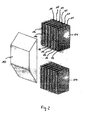
- the in Fig. 1 illustrated heat exchanger 01 which is designed in the design of a plate heat exchanger, is used for preheating of melt 02 using flue gas 03.
- the melt consists of a mixture of broken glass and glass batch before it is introduced into a melting tank for the production of glass.
- the melt is preheated in the heat exchanger 01 to several 100 ° C and the heating gas is preferably used in the glass melting plant resulting flue gas in order to achieve a corresponding energy savings can.
- the heat exchanger 01 is composed in modules of individual heat exchanger modules 04.
- the in Fig. 1 illustrated heat exchanger 01 is formed, for example, of five in a vertical row superposed heat exchanger modules 04.
- On the uppermost heat exchanger module 04 a Schmelzgutholzgabe 05 is arranged, through which the melt is conveyed from above into the heat exchanger 01.
- Below the lowermost heat exchanger module 04 of the heat exchanger 01 a Schmelzgutausgabe 06 is arranged, where the preheated melt is removed and then conveyed to a melting tank, not shown, the glass melting plant.
- the flue gas 03 used for preheating the melt 02 is conveyed via a flue gas inlet 07 into the lowermost heat exchanger module 04 and exits the top heat exchanger module 04 through a flue gas outlet 08 again from the heat exchanger 01.
- a flue gas outlet 08 To promote the flue gas 03 while a fan 09 is provided in the flue gas outlet 08, which builds a negative pressure and sucks the flue gas 03 through the heat exchanger 01.
- Deflection plates 10 are fastened between the various heat exchanger modules 04 so that the flue gas 03 flows meandering upward and transfers its heat to the melt 02 without direct contact with the melt 02 through the partitions of the heat exchanger modules 04.
- FIG. 2 two heat exchanger modules 04 and an associated baffle 10 are shown in perspective view.
- the heat exchanger modules 04 are arranged vertically aligned one above the other, so that form a plurality of vertically upwardly extending Schmelzgutkanäle 11 through which the melt 02 slips down under the influence of gravity and without further mechanical conveyors.
- each flue gas channels 12 are formed, which are traversed transversely to the conveying direction of the melt 02 from the flue gas 03.
- partitions 13 are present, which separate the Schmelzgutkanäle 11 of the flue gas ducts 12, so that the preheating of the melt through the flue gas takes place indirectly and without direct contact between the flue gas and the melt.
- Fig. 3 shows a heat exchanger module 04 with a Schntnelzgutkanal 11 and two broken flue gas ducts 12 in perspective view.
- the dividing walls 13 between the flue gas ducts 12 and the Schmelzgutkanälen 11 each have a plurality of slot openings 14 are provided, which extend transversely to the conveying direction of the melt 02 with its longitudinal axis. Through the slot openings 14, the water vapor formed during the preheating of the melt 02 in the melt channels 11 can be sucked off and removed via the flue gas channels 12.
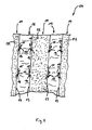
- Fig. 4 shows the heat exchanger module 04 in schematic cross-section along the section line II.
- the resulting in the melted material channels 02 in the melt 02 by the preheating water vapor 15 is sucked through the slot openings 14 into the flue gas channels 12 and discharged together with the flue gas 03.
- Strömungsleitmaschine 16 namely wedge-shaped strips on the underside of the slot openings 14, a deflection of the flue gas flow and the water vapor flow is effected so that no flue gas 03 can penetrate through the slot openings 14 in the Schmelzgutkanäle 11 due to the pressure gradient between the flue gas ducts 12 and the Schmelzgutkanälen 11 ,
Landscapes
- Engineering & Computer Science (AREA)
- Physics & Mathematics (AREA)
- Thermal Sciences (AREA)
- Mechanical Engineering (AREA)
- General Engineering & Computer Science (AREA)
- Chemical & Material Sciences (AREA)
- Materials Engineering (AREA)
- Organic Chemistry (AREA)
- Glass Melting And Manufacturing (AREA)
- Heat-Exchange Devices With Radiators And Conduit Assemblies (AREA)
Applications Claiming Priority (1)
| Application Number | Priority Date | Filing Date | Title |
|---|---|---|---|
| DE102008030161A DE102008030161B3 (de) | 2008-06-27 | 2008-06-27 | Wärmetauscher und Verfahren zum Betrieb eines Wärmetauschers |
Publications (2)
| Publication Number | Publication Date |
|---|---|
| EP2138465A2 true EP2138465A2 (fr) | 2009-12-30 |
| EP2138465A3 EP2138465A3 (fr) | 2013-03-20 |
Family
ID=40786156
Family Applications (1)
| Application Number | Title | Priority Date | Filing Date |
|---|---|---|---|
| EP09007294A Withdrawn EP2138465A3 (fr) | 2008-06-27 | 2009-06-02 | Echangeur thermique et procédé de mise en oeuvre d'un échangeur thermique |
Country Status (2)
| Country | Link |
|---|---|
| EP (1) | EP2138465A3 (fr) |
| DE (1) | DE102008030161B3 (fr) |
Cited By (21)
| Publication number | Priority date | Publication date | Assignee | Title |
|---|---|---|---|---|
| US9676644B2 (en) | 2012-11-29 | 2017-06-13 | Johns Manville | Methods and systems for making well-fined glass using submerged combustion |
| USRE46462E1 (en) | 2011-10-07 | 2017-07-04 | Johns Manville | Apparatus, systems and methods for conditioning molten glass |
| US9815726B2 (en) | 2015-09-03 | 2017-11-14 | Johns Manville | Apparatus, systems, and methods for pre-heating feedstock to a melter using melter exhaust |
| US9926219B2 (en) | 2012-07-03 | 2018-03-27 | Johns Manville | Process of using a submerged combustion melter to produce hollow glass fiber or solid glass fiber having entrained bubbles, and burners and systems to make such fibers |
| US9957184B2 (en) | 2011-10-07 | 2018-05-01 | Johns Manville | Submerged combustion glass manufacturing system and method |
| US9982884B2 (en) | 2015-09-15 | 2018-05-29 | Johns Manville | Methods of melting feedstock using a submerged combustion melter |
| USRE46896E1 (en) | 2010-09-23 | 2018-06-19 | Johns Manville | Methods and apparatus for recycling glass products using submerged combustion |
| US10041666B2 (en) | 2015-08-27 | 2018-08-07 | Johns Manville | Burner panels including dry-tip burners, submerged combustion melters, and methods |
| US10081565B2 (en) | 2010-06-17 | 2018-09-25 | Johns Manville | Systems and methods for making foamed glass using submerged combustion |
| US10081563B2 (en) | 2015-09-23 | 2018-09-25 | Johns Manville | Systems and methods for mechanically binding loose scrap |
| US10144666B2 (en) | 2015-10-20 | 2018-12-04 | Johns Manville | Processing organics and inorganics in a submerged combustion melter |
| US10196294B2 (en) | 2016-09-07 | 2019-02-05 | Johns Manville | Submerged combustion melters, wall structures or panels of same, and methods of using same |
| US10233105B2 (en) | 2016-10-14 | 2019-03-19 | Johns Manville | Submerged combustion melters and methods of feeding particulate material into such melters |
| US10246362B2 (en) | 2016-06-22 | 2019-04-02 | Johns Manville | Effective discharge of exhaust from submerged combustion melters and methods |
| US10301208B2 (en) | 2016-08-25 | 2019-05-28 | Johns Manville | Continuous flow submerged combustion melter cooling wall panels, submerged combustion melters, and methods of using same |
| US10322960B2 (en) | 2010-06-17 | 2019-06-18 | Johns Manville | Controlling foam in apparatus downstream of a melter by adjustment of alkali oxide content in the melter |
| US10392285B2 (en) | 2012-10-03 | 2019-08-27 | Johns Manville | Submerged combustion melters having an extended treatment zone and methods of producing molten glass |
| US10472268B2 (en) | 2010-06-17 | 2019-11-12 | Johns Manville | Systems and methods for glass manufacturing |
| WO2020008128A1 (fr) | 2018-07-03 | 2020-01-09 | Saint-Gobain Glass France | Preparation de matieres premieres pour four verrier |
| US10837705B2 (en) | 2015-09-16 | 2020-11-17 | Johns Manville | Change-out system for submerged combustion melting burner |
| US11613488B2 (en) | 2012-10-03 | 2023-03-28 | Johns Manville | Methods and systems for destabilizing foam in equipment downstream of a submerged combustion melter |
Families Citing this family (6)
| Publication number | Priority date | Publication date | Assignee | Title |
|---|---|---|---|---|
| DE102009054354B3 (de) | 2009-11-24 | 2011-06-09 | Beteiligungen Sorg Gmbh & Co. Kg | Verfahren und Vorrichtung zum thermischen Entwässern und Vorwärmen von Gemenge für Glasschmelzanlagen |
| DE102010023018B3 (de) | 2010-06-08 | 2011-05-19 | Beteiligungen Sorg Gmbh & Co. Kg | Verfahren und Vorrichtung zum Beschicken von Vorwärmern für Glas-Schmelzanlagen |
| DE102010025365B3 (de) * | 2010-06-28 | 2011-06-16 | Beteiligungen Sorg Gmbh & Co. Kg | Vorrichtung zum Trocknen und Vorwärmen von partikelförmigem Beschickungsgut |
| DE102010026487B4 (de) | 2010-07-07 | 2012-10-04 | Zippe Gmbh U. Co. Kg | Vorwärmvorrichtung zum Vorwärmen von Glasgemenge |
| CN107447066B (zh) * | 2017-09-21 | 2022-08-16 | 长治市方圣喷吹技术有限公司 | 一体式高炉喷吹煤粉预热器 |
| DE202018105818U1 (de) * | 2018-10-11 | 2020-01-21 | Zippe Gmbh & Co. Kg | Vorrichtung zum Vorwärmen von Schmelzgut zur Glasherstellung unter Nutzung von Rauchgas |
Citations (1)
| Publication number | Priority date | Publication date | Assignee | Title |
|---|---|---|---|---|
| DE4213481C1 (en) | 1992-04-24 | 1993-05-27 | Zippe Gmbh + Co, 6980 Wertheim, De | Pre-warming melt material consisting of broken glass - by passing material down through vertical columns while passing heating gas in reverse direction |
Family Cites Families (2)
| Publication number | Priority date | Publication date | Assignee | Title |
|---|---|---|---|---|
| US4303434A (en) * | 1980-09-08 | 1981-12-01 | Owens-Illinois, Inc. | Method and apparatus for preheating pulverous materials prior to their introduction into a melting furnace |
| US4353726A (en) * | 1981-04-17 | 1982-10-12 | Owens-Illinois, Inc. | Method and apparatus for preheating pulverous materials prior to their introduction into a melting furnace |
-
2008
- 2008-06-27 DE DE102008030161A patent/DE102008030161B3/de active Active
-
2009
- 2009-06-02 EP EP09007294A patent/EP2138465A3/fr not_active Withdrawn
Patent Citations (1)
| Publication number | Priority date | Publication date | Assignee | Title |
|---|---|---|---|---|
| DE4213481C1 (en) | 1992-04-24 | 1993-05-27 | Zippe Gmbh + Co, 6980 Wertheim, De | Pre-warming melt material consisting of broken glass - by passing material down through vertical columns while passing heating gas in reverse direction |
Cited By (27)
| Publication number | Priority date | Publication date | Assignee | Title |
|---|---|---|---|---|
| US10081565B2 (en) | 2010-06-17 | 2018-09-25 | Johns Manville | Systems and methods for making foamed glass using submerged combustion |
| US10472268B2 (en) | 2010-06-17 | 2019-11-12 | Johns Manville | Systems and methods for glass manufacturing |
| US10322960B2 (en) | 2010-06-17 | 2019-06-18 | Johns Manville | Controlling foam in apparatus downstream of a melter by adjustment of alkali oxide content in the melter |
| USRE46896E1 (en) | 2010-09-23 | 2018-06-19 | Johns Manville | Methods and apparatus for recycling glass products using submerged combustion |
| US9957184B2 (en) | 2011-10-07 | 2018-05-01 | Johns Manville | Submerged combustion glass manufacturing system and method |
| USRE46462E1 (en) | 2011-10-07 | 2017-07-04 | Johns Manville | Apparatus, systems and methods for conditioning molten glass |
| US11233484B2 (en) | 2012-07-03 | 2022-01-25 | Johns Manville | Process of using a submerged combustion melter to produce hollow glass fiber or solid glass fiber having entrained bubbles, and burners and systems to make such fibers |
| US9926219B2 (en) | 2012-07-03 | 2018-03-27 | Johns Manville | Process of using a submerged combustion melter to produce hollow glass fiber or solid glass fiber having entrained bubbles, and burners and systems to make such fibers |
| US11613488B2 (en) | 2012-10-03 | 2023-03-28 | Johns Manville | Methods and systems for destabilizing foam in equipment downstream of a submerged combustion melter |
| US10392285B2 (en) | 2012-10-03 | 2019-08-27 | Johns Manville | Submerged combustion melters having an extended treatment zone and methods of producing molten glass |
| US9676644B2 (en) | 2012-11-29 | 2017-06-13 | Johns Manville | Methods and systems for making well-fined glass using submerged combustion |
| US10041666B2 (en) | 2015-08-27 | 2018-08-07 | Johns Manville | Burner panels including dry-tip burners, submerged combustion melters, and methods |
| US10955132B2 (en) | 2015-08-27 | 2021-03-23 | Johns Manville | Burner panels including dry-tip burners, submerged combustion melters, and methods |
| US9815726B2 (en) | 2015-09-03 | 2017-11-14 | Johns Manville | Apparatus, systems, and methods for pre-heating feedstock to a melter using melter exhaust |
| US9982884B2 (en) | 2015-09-15 | 2018-05-29 | Johns Manville | Methods of melting feedstock using a submerged combustion melter |
| US10837705B2 (en) | 2015-09-16 | 2020-11-17 | Johns Manville | Change-out system for submerged combustion melting burner |
| US10081563B2 (en) | 2015-09-23 | 2018-09-25 | Johns Manville | Systems and methods for mechanically binding loose scrap |
| US10435320B2 (en) | 2015-09-23 | 2019-10-08 | Johns Manville | Systems and methods for mechanically binding loose scrap |
| US10144666B2 (en) | 2015-10-20 | 2018-12-04 | Johns Manville | Processing organics and inorganics in a submerged combustion melter |
| US10246362B2 (en) | 2016-06-22 | 2019-04-02 | Johns Manville | Effective discharge of exhaust from submerged combustion melters and methods |
| US10793459B2 (en) | 2016-06-22 | 2020-10-06 | Johns Manville | Effective discharge of exhaust from submerged combustion melters and methods |
| US10301208B2 (en) | 2016-08-25 | 2019-05-28 | Johns Manville | Continuous flow submerged combustion melter cooling wall panels, submerged combustion melters, and methods of using same |
| US11396470B2 (en) | 2016-08-25 | 2022-07-26 | Johns Manville | Continuous flow submerged combustion melter cooling wall panels, submerged combustion melters, and methods of using same |
| US10196294B2 (en) | 2016-09-07 | 2019-02-05 | Johns Manville | Submerged combustion melters, wall structures or panels of same, and methods of using same |
| US10233105B2 (en) | 2016-10-14 | 2019-03-19 | Johns Manville | Submerged combustion melters and methods of feeding particulate material into such melters |
| FR3083539A1 (fr) | 2018-07-03 | 2020-01-10 | Saint-Gobain Glass France | Preparation de matieres premieres pour four verrier |
| WO2020008128A1 (fr) | 2018-07-03 | 2020-01-09 | Saint-Gobain Glass France | Preparation de matieres premieres pour four verrier |
Also Published As
| Publication number | Publication date |
|---|---|
| DE102008030161B3 (de) | 2009-07-23 |
| EP2138465A3 (fr) | 2013-03-20 |
Similar Documents
| Publication | Publication Date | Title |
|---|---|---|
| DE102008030161B3 (de) | Wärmetauscher und Verfahren zum Betrieb eines Wärmetauschers | |
| DE4213481C1 (en) | Pre-warming melt material consisting of broken glass - by passing material down through vertical columns while passing heating gas in reverse direction | |
| DE2634281C3 (de) | Düsenplatte zum Ziehen von Glasfasern | |
| EP0649821B1 (fr) | Dispositif pour l'échauffement ou le refroidissement de feuilles ou de rubans de verre | |
| DE4000358C2 (fr) | ||
| EP2312953B1 (fr) | Four boulangerie avec appareil à buées | |
| DE2636998C3 (de) | Düsenplatte zum Ziehen von Glasfasern | |
| DE1956495A1 (de) | Vorherd fuer glasverarbeitende Maschinen | |
| DE3107270A1 (de) | Verfahren und vorrichtung zur zufuehrung von verbrennungsluft zu den entgegengesetzten enden der regeneratoren eines regenerativ-glasschmelzofens | |
| DE3133467C2 (de) | Verfahren zum Vorerhitzen von Glasgemenge in einem Wärmetauscher | |
| DE102009019454A1 (de) | Vorrichtung zum Vorwärmen von Glasscherbengemengen | |
| DE1769755B2 (de) | Kolonne zur trennung oder reinigung eines stoffgemisches durch kristallisieren | |
| DE3710901C2 (fr) | ||
| DE3416317A1 (de) | Verfahren und vorrichtung zum vorwaermen von rohstoffen fuer die glasherstellung, insbesondere eines glasscherbengemenges | |
| EP4522360B1 (fr) | Dispositif de coulée et procédé de préchauffage d'un dispositif de transport de fusion d'un dispositif de coulée | |
| DE4007115C2 (fr) | ||
| DE1596624C3 (de) | Vorrichtung zum Fördern von Glastafeln längs eines Gaspolsters | |
| DE4446575C2 (de) | Verfahren und Vorrichtung zum Abtrennen von Galle bei Schmelzprozessen von Glas | |
| DE19643699C1 (de) | Schachtkühler | |
| DE69002880T2 (de) | Verfahren und Vorrichtung zur Herstellung einer gleichmässigen Temperatur im Vorherd der Glaserzeugung. | |
| DE102005013468B4 (de) | Vorrichtung und Verfahren zum Läutern von Glas | |
| DE102004012607B4 (de) | Vorrichtung und Verfahren zur thermischen Behandlung von Süßwarenmassen | |
| DE10150041B4 (de) | Austrag-Kühleinrichtung für eine Druckmaschine | |
| DE3008960A1 (de) | Kuehlvorrichtung fuer eine floatglasanlage | |
| EP0411112B1 (fr) | Echangeur de chaleur |
Legal Events
| Date | Code | Title | Description |
|---|---|---|---|
| PUAI | Public reference made under article 153(3) epc to a published international application that has entered the european phase |
Free format text: ORIGINAL CODE: 0009012 |
|
| AK | Designated contracting states |
Kind code of ref document: A2 Designated state(s): AT BE BG CH CY CZ DE DK EE ES FI FR GB GR HR HU IE IS IT LI LT LU LV MC MK MT NL NO PL PT RO SE SI SK TR |
|
| RAP1 | Party data changed (applicant data changed or rights of an application transferred) |
Owner name: ZIPPE GMBH & CO. KG |
|
| PUAL | Search report despatched |
Free format text: ORIGINAL CODE: 0009013 |
|
| AK | Designated contracting states |
Kind code of ref document: A3 Designated state(s): AT BE BG CH CY CZ DE DK EE ES FI FR GB GR HR HU IE IS IT LI LT LU LV MC MK MT NL NO PL PT RO SE SI SK TR |
|
| AX | Request for extension of the european patent |
Extension state: AL BA RS |
|
| RIC1 | Information provided on ipc code assigned before grant |
Ipc: F28D 21/00 20060101ALI20130208BHEP Ipc: F28D 9/00 20060101ALI20130208BHEP Ipc: C03B 3/02 20060101AFI20130208BHEP Ipc: F28F 9/26 20060101ALI20130208BHEP |
|
| STAA | Information on the status of an ep patent application or granted ep patent |
Free format text: STATUS: THE APPLICATION IS DEEMED TO BE WITHDRAWN |
|
| 18D | Application deemed to be withdrawn |
Effective date: 20130921 |