EP2138654A2 - Abri - Google Patents
Abri Download PDFInfo
- Publication number
- EP2138654A2 EP2138654A2 EP09075259A EP09075259A EP2138654A2 EP 2138654 A2 EP2138654 A2 EP 2138654A2 EP 09075259 A EP09075259 A EP 09075259A EP 09075259 A EP09075259 A EP 09075259A EP 2138654 A2 EP2138654 A2 EP 2138654A2
- Authority
- EP
- European Patent Office
- Prior art keywords
- rafters
- roof
- roofing
- segments
- segment
- Prior art date
- Legal status (The legal status is an assumption and is not a legal conclusion. Google has not performed a legal analysis and makes no representation as to the accuracy of the status listed.)
- Withdrawn
Links
Images




Classifications
-
- E—FIXED CONSTRUCTIONS
- E04—BUILDING
- E04H—BUILDINGS OR LIKE STRUCTURES FOR PARTICULAR PURPOSES; SWIMMING OR SPLASH BATHS OR POOLS; MASTS; FENCING; TENTS OR CANOPIES, IN GENERAL
- E04H15/00—Tents or canopies, in general
- E04H15/18—Tents having plural sectional covers, e.g. pavilions, vaulted tents, marquees, circus tents; Plural tents, e.g. modular
Definitions
- the present invention relates to a mobile or stationary canopy.
- the invention further relates to a roof segment and a kit and a gazebo.
- Shelters are used to protect against rain and sunshine (sunshades) and for privacy. These can be located on the outer walls of solid buildings, or provided with a frame and be independent of buildings freely deployable. Ultimately, it is about creating a space under the canopy, which is protected from rain, sunshine (shading) or unwanted glances.
- mobile roofs are known from the prior art, in which a rod consisting of pipes or wooden posts is assembled and subsequently a cover is made with a tarpaulin.
- side surfaces can be provided with a tarp or other side elements, so that the roof is a kind of partially closed pavilion or walk-in tent.
- Crucial for the intended use is that the covered area can be adjusted. For this reason, there is a need for canopies, which go back to a modular system that allows adaptation to the required area, which has to protect against rain, sunlight and unwanted glances.
- the roofing system according to the invention in the context of the invention a roofing system, comprises at least one central part with receiving devices for roof rafters frictionally connected to the central part, which have receiving devices for roof segments. According to the receiving devices of the rafters are designed as a guide rail for the roof segments.
- the roof segments are trigonal configured with outwardly to adjacent rafters towards ellipsoidal shaped sides and are flexible to the extent that they can be inserted and clamped in the guide rails of the rafters.
- the middle part has receiving devices, which serve to receive the rafters, wherein the rafters are additionally fastened by means of fastening means on the central part and are thus positively connected thereto.
- the middle part is not displaceable but fixed.
- a rafter is preferably formed of a square tube with guide bar and extends centrally into the middle part (Ronde), which can be completed by a cap at the bottom and a cap above.
- the rafter between the cap and middle part has on both sides a receiving device, according to the invention a guide slot or guide rail, for retractable weatherproof roof segments.
- the roof segments are inserted on the one hand in the rafters and can be additionally secured by a rafter cap at the lower end of the rafters for failure insurance.
- the shape of a roof segment is preferably triangular in plan view, wherein the outside of the roof segment may be rounded or curved.
- the roof segments preferably have an ellipsoidal shape on the side to be introduced into the rafters. If the rafters are bent, a roof segment at the top of the converging straight sides on a corresponding bend, so that a roof segment can be inserted into the guide rails of the rafters.
- the material thickness of a roof segment according to the invention preferably has the strength of the gap of the guide rails, so that the roof segment and rafters are flush and therefore watertight.
- a roof segment can be fixed on both sides in the guide slot of two rafters and so in the context of the present invention, a segment is formed.
- no more than two persons are required to set up a system according to the invention.
- the roofing system can be erected by means of a vertical support connected to the central part of the system and / or by means of vertical supports arranged by means of the outer end of the rafters facing away from the center piece.
- the supports are thus variably attached to the central part and / or the rafters.
- the preferred embodiment can be adapted to specific requirements and can be used variably.
- the supports are attached via fasteners to the central part and the rafters.
- the roofing system can be fastened to a building structure. It can be attached to the central part means, which serve for connection to a building, such as a house wall. Accordingly, rafters are attached to only one side of the middle section. The attachment to the structure can be done on the rafters.
- the advantageous embodiment can not only exist as an independent system, but also be arranged on a, preferably vertical surface, whereby it can be used as an example Car Port.
- a building body for example, a house wall or a wooden head is considered, so that, as a result, e.g. a canopy can be realized, which does not require any support, but may also additionally have one or more supports according to the invention.
- the roof segments made of plastic, metal and / or wood, preferably acrylic, Plexiglas, PVC or polycarbonate.
- the material for the retractable roof segment is preferably plastic, comprising acrylic, Plexiglas, PVC or polycarbonate provided.
- the material may be transparent or opaque and of different colors, depending on the requirements of the roof segment or the roof should meet. But there are also other materials suitable for a roof segment, such as metal or wood. It is particularly advantageous that the roof segments are easy to clean and weather-resistant; they are easy to clean (for example by means of water / steam)
- a material thickness for the roof segments of 2 mm to 5 mm.
- the preferred embodiment is particularly wind and weather resistant, but has a low weight, making it flexible and transportable.
- An optimal connection of the roof segments with the rafters also guarantees that the preferred embodiment is waterproof.
- the embodiments are fast and efficient to produce. If a flexible material is used, a greater material thickness than the gap of the guide rail is conceivable for the roof segment, whereby the material of the roof segment is compressed when inserted into the rail and thus a tight completion of roof segment and rafters is ensured particularly advantageous. A seal can thus be done by squeezing the roof segment material in the guide rail of the rafters.
- the supports on a hollow profile are preferably made of pipes, wherein the material used is wood, stainless steel, galvanized and / or powder-coated steel or aluminum.
- the advantageous embodiment allows a light but stable construction. Furthermore are not visible due to the hollow profile, fittings, but are located within the profiles.
- the supports are anchored to the ground. So that the supports can be connected to the ground, ground sleeves are provided with pegs at its lower end. This ensures that the advantageous embodiment is designed to be flexible and stable and that a stress according to the weather is ensured. It is advantageous that the bottom sleeves and supports consist of tubes which can be inserted into one another with an exact fit and can be mounted height-adjustable by means of bores. The system is thus positioned and fixed by bottom sleeves with variable bores for the desired height compensation (height leveling) on the ground and, alternatively, by an internal thread provided for receiving so-called ground spikes.
- the ground sleeves are also provided with a so-called welded circular blank, each with three holes, which serve for receiving Erdnägeln or cap screws or for direct attachment to hard ground.
- Each element consists of a round outer support and a welded rectangular flat rafter cap with two integrated holes for two threaded bolts, over which pre-bent rafters are attached on one side.
- the system can be brought to a stable uprising even without anchoring, even on uneven ground.
- feet are provided, which may be connected to the supports, for example, are inserted in the hollow profile. Either the feet and / or the support itself is adjustable in length in the vertical orientation, so that each support can be individually adapted to the respective substrate.
- the rafters are stabilized by cross struts.
- the rafters are attached to the central part and the rafters are stabilized by cross struts, which are fastened by means of fasteners on the rafters.
- the transverse struts are preferably made of a hollow profile, for example pipes. As materials, metals, wood or plastics are preferred, which can be used in different forms. Due to the advantageous embodiment, a high stability is achieved despite a low weight.
- the height of the receiving device of the rafters is between 2 mm and 10 mm.
- the rafters are advantageously made of a bent square tube on the constructively preferably every 400 mm by means of fastening means, such as a countersunk screw or a cylinder head screw, a flat bar is screwed. This can also be flanged. Alternatively, the flat bar and the four-manpower existing rafters be extruded, whereby the production is simplified and the manufacturing cost can be reduced.
- the flat web forms in cross section the actual rafter and is flexibly attached to the square tube.
- the flat bar is spaced apart from the square tube and thus forms a receiving device which serves as a guide rail for a roof segment to be inserted.
- the height of the distance is formed corresponding to the material thickness of the roof segments, ie it is thus dependent on the material thickness of the roof segments.
- a height distance of the receiving device is provided up to 10 mm.
- the tension between the receiving device and roof segment is positively.
- the bracing also ensures that no water passes between roof segment and rafters, so therefore a waterproof embodiment.
- means for electrification and / or illumination are integrated into the system.
- one or more electric cables can be passed through the entire roofing system from above or below through the square tube of the rafters, through the welded-on cap, through the support and through the round opening provided on the base of this support for one or more electrical connections ( possible with all pipes).
- a lighting in the cover or an (infrared) heating can be inserted into the rafters.
- the preferred embodiment allows illumination and / or heating without the wiring being visible to the viewer.
- the middle part is formed from a central tube and attached, accurately fitting square sockets for rafters.
- the middle part is made of a central tube to which preferably three to six square sockets or receiving devices are preferably welded. These welded sockets are intended for receiving the rafters. In the sockets and in the rafters holes are provided through which the rafters and the middle part are connected to each other with fasteners such as cap screws or threaded bolts.
- a closed welded cap Under a ring of the central tube (-vons) a closed welded cap is provided with a lower central bore for a lighting fixture to be used. On the ring of the central tube a cap is provided, which ensures the required almost complete water resistance.
- the roof segments, which abut the central tube, are surmounted by the oversized cap and thus ensure a virtually watertight or water-repellent drainage.
- the Cover segment is attached to the center tube with sealing ring and thus also ensures the weatherproof use, possibly with illumination (lighting equipment).
- a plurality of roofing systems on the front sides of the roof segments are connected to each other.
- a plurality of roofing systems can be connected to each other by means of the ends of adjacent, straight-cut roof segments and a gutter construction.
- the rafters for connecting pavilions over the supports are preferably suitable for this purpose.
- roofs of the same or different shape can be combined with each other. If hexagonal roofs are connected together, so creates a shape of a honeycomb pattern.
- the use of only one roof segment is conceivable.
- the gutter construction can also be used as a gutter. It is advantageous if, in particular in the connection of several roofing systems, a device is integrated into the system, which allows a drain of any accumulated rainwater. It is advantageous if the device is a perforation device, which dissipates the rainwater through the supports in the ground. Alternatively, a connector connect the roofing systems together, this design holds a space for the flow of rainwater.
- the invention further relates to a roof segment, in particular a trigonal roof segment with outwardly ellipsoidally shaped sides, as part of a roofing system.
- the roof segments preferably have an ellipsoidal shape on the side introduced into the rafters.
- the roof segments may be straight or ellipsoidal at the front. If the rafters are bent, a roof segment at the top of the converging straight sides on a corresponding bend, so that a roof segment can be inserted into the guide rails of the rafters.
- the roof segments are preferably made of plastic, metal and / or wood, for example acrylic, plexiglass, polycarbonate or PVC.
- the material may be transparent or opaque and of different colors.
- the roof segment according to the invention represents a technical advance, since it is substantially flat before connection to the rafters, but has a curved surface after the connection with the rafter due to the press-fitting therein.
- the roof segments are light and flexible and can be easily inserted into the intended receiving devices of the rafters.
- the connection of the rafters with the roof segments the stability of the entire canopy construction is achieved.
- these roof segments offer rain, sight and sun protection, which can be taken from a roof of this kind expected.
- the roof segments are easy to clean and weather-resistant.
- the invention also relates to a kit providing a roofing system according to the present invention.
- a kit providing a roofing system according to the present invention.
- at least one central part is included in the kit, to which the rafters also contained in the kit are attached.
- the middle part has for this purpose special recording devices that serve to receive the rafters.
- the attachment of the rafters is additionally supported by fasteners.
- the kit also contains crossbars that stabilize the rafters.
- the rafters and the crossbars are preferably made of a hollow profile.
- the roof segments contained in the kit are introduced and braced, the roof segments can be made of different materials. Also, different colors are conceivable.
- the kit contained columns continue to serve the construction of the canopy.
- the supports can be centrally attached to the central part or to the outer, the middle part facing away from the rafters. Also preferred embodiments are conceivable, which allow the attachment of the canopy to a vertical surface (structure). For this purpose, it is advantageous if the middle part has receiving devices for rafters only on one side. All connections of the roofing system are screwable or pluggable and thus reversible. As a result, the system is mobile and can be built for temporary use quickly and easily, with two persons are sufficient for the construction. The system is also weather-resistant and very easy-care.
- the invention also relates to a pavilion, which can be realized by means of the roofing system according to the invention.
- the pavilion can be used for private or business use.
- Preferred embodiments include a canopy, a honeycomb gazebo (multiple interconnected roofing systems according to the invention) or as a point of sale.
- the invention relates to the mobile and / or stationary creation of a weather-independent pavilion or a fixed canopy based on plug or Verschraubelementen alternatively with lighting elements and / or heating elements.
- the load-bearing elements are either made of stainless steel, galvanized and / or powder-coated steel or made of aluminum and thus represent a lightweight and flexible construction.
- the screwing of the individual elements is preferably made of Optimiznutmuttern or stainless steel threaded bolt.
- the individual elements of the system according to the invention may also consist of extruded stainless steel or aluminum shapes in mass production.
- the roof segment can be standard be made of plexiglass or a similar material in any shape, color, design and mass of preferably 2-5 mm thickness as needed.
- the benefit of the invention is in addition to the aesthetic implementation in the almost indestructible, weatherproof, mobile, easy to clean and easy to handle for many applications up and dismantling.
- a complete roofing and carrier system as a pavilion, as a canopy, as a fair, market or bar or even as a roofing system of a large terrace in a relatively short time to produce and rebuild.
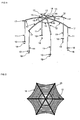
- FIG1 shows an overview of the roofing according to the invention.
- a single segment which includes a bottom sleeve 10 with various holes for height compensation, pegs 18 for stabilization, an attachable support 11 with variable mounting holes for receiving attachments and a welded rafters 12.
- cable fasteners, heating elements or windbreaking elements can be attached to the rafter 12 by means of the bores.
- the rafter 12 is preferably formed from a square tube with guide web and extends centrally into a middle part (Ronde) 13, which is covered by a cap 14. Under the cover 14, a lighting element may be mounted, and the underside of the central part 13 may be covered by a lower cap.
- Cross struts 15, which are mounted between the rafters 12, serve to stabilize the canopy.
- the rafters 12 has between cap 14 and middle part 13 on both sides of a receiving device, such as a guide slot, which is suitable for receiving retractable weatherproof roof segments 16, which in turn secured below by a rafter cap 17 at the lower end of the rafters 12 for failure backup are.
- a receiving device such as a guide slot
- FIG. 2 shows a plan view of the roof with roof segments.
- the roof segments 12 made of Plexiglas are introduced into the receiving device and secured by rafter caps.
- the roof segments 12 in turn are attached to the central part 13.
- the use of six roof segments 16 creates a hexagonal roof.
- FIG. 3 is a schematic representation of a side view of a partial roof with roof segments.
- the roof segments 16 are inserted into the rafters 12 and the system is by means of supports 11 on a floor 24, the floor 24 need not be flat. Not shown is the possibility of Erdbefest Trent using ground sockets and pegs.
- FIG. 4 shows a side view of a preferred embodiment of the canopy.
- the system can be easily varied in size, so that only four roof segments 16 are integrated into the rafters 12 and so the diameter of the canopy is reduced.
- the system can be applied by means of supports 11 on a flat or uneven ground 24.
- a stabilization of the system can be achieved by fasteners such as pegs and a ground socket.
- FIG. 5.1 to FIG. 5.3 show the middle part.
- the middle part 13 is preferably mounted in the center of the canopy and serves to receive the rafters 12.
- the rafters 12 are inserted into receiving devices 20 and connected by means of fastening devices 19, such as holes and fasteners such as screws frictionally connected to the central part 13.
- FIG. 5.2 shows a side view of the middle part.
- the middle part 13 further has cable bushings 21, which serve to receive and pass through cables. This allows cables to be routed easily and quickly through the system without disruptive influences.
- the middle part 13 preferably has a blank 22 which simplifies assembly of the system.
- the middle part 13 can be varied according to individual requirements and be designed with 4, 6, or more receiving devices 20 for rafters.
- FIG. 5.3 shows a cross section of a receiving device 20 of the central part 13.
- the rafters 12 are inserted into the receiving devices 20 of the central part 13 and held by the inventive shape of the central part 13 in the receiving devices 20.
- An additional attachment of the rafters 12 and the middle part is achieved by the fastening devices 19.
- FIG. 6.1 to FIG. 6.3 show a rafter.
- FIG. 6.1 represents a side view of a rafter.
- the rafter 12 is preferably made of metal, but can also be made of plastic or wood.
- cable glands 21 are embedded, whereby cables can be distributed in the interior of the system and are not visible to the viewer.
- Fasteners 19 in the rafters 12 are used to attach the web and the crossbars.
- heating elements, wiring or bracing may be attached to the fasteners of the roof rafter.
- FIG. 6.2 shows a plan view of the roof rafter.
- the grommets 21 are recessed into the rafters 12 so that the cables passed are not visible to the viewer and power is supplied to electrical appliances located on or under or in the system.
- FIG 6.3 is the cross section of a rafter 12 darg Lake.
- the rafter 12 is preferably made of a bent square tube 12.1 in the constructive preferably every 400 mm with fasteners (eg a countersunk or cylinder head screw) a flat web 20.1 is applied.
- This flat web 20.1 forms with the square tube 12.1 at the same time a receiving device 20, a guide rail, which serves to receive the roof segment to be inserted. Roof roof segment is clamped in and clamped by the receiving device 20.
- the flat web 20.1 and the rafter 12 consisting of a four-bar trunk 12.1 can be extruded.
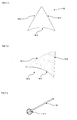
- FIG. 7.1 to FIG. 7.3 show a roof segment.
- the roof segments 16 are preferably flexible plastic panels, such as acrylic or Plexiglas, which have a domed shape once inserted into the rafters.
- the roof segment 16 consists of two opposite ellipsoidal sides 16.2 and a front side 16.3, which may be ellipsoidal or straight.
- FIG. 7.2 shows a spatial view of a roof segment.
- the roof segment 16 has no continuous radius, but preferably an elliptical arc, ie the sides 16.2 extend ellipsoidal to the rafters.
- the roof segments 16 may also be shaped such that the front 16.3 not inserted into the rafters is straight.
- FIG. 7.1 is a plan view of a roof segment shown.
- the roof segments 16 are preferably flexible plastic panels, such as acrylic or Plexiglas, which have a domed shape once inserted into the rafters.
- the roof segment 16 consists of two opposite ellipsoidal sides 16.2 and
- FIG. 7.3 shows a side view of the border profile of a roof segment.
- the roof segment has at the end of a bordering profile 16.1, through which the roof segment 16 is additionally held in the rafters 12. This creates a positive connection, wherein the connection can be supported by fastening means.
- FIG. 8.1 and FIG. 8.2 show a variant of the roof.
- FIG. 8.1 shows a side view of an embodiment of the system according to the invention and FIG a plan view.
- the roofing is fastened to a floor 24 via a central support 11.
- the attachment can also be supported by ground sockets or pegs.
- the central support 11 is preferably fixed to the central part 13.
- the rafters 12 are also connected to the central part 13 and serve to receive the roof segments 16.
- the embodiment requires less space and can be centrally mounted.
- FIG. 9.1 and FIG. 9.2 show a side view and a plan view of another embodiment of the canopy designed as a canopy.
- the rafters 12 are mounted on the central part 13, however, the middle part 13 on one side receiving devices for the rafters 12 on.
- the roof segments 16 are connected only on one side of the canopy with the rafters 12.
- the embodiment is placed on a floor 24 and possibly attached.
- the embodiment variant is preferably fastened to a vertical surface, wherein due to the intrinsic stability of the embodiment variant, no additional attachment by means of fastening means is necessary, but optionally additional stability can be achieved.
- an embodiment is preferred in which only one roof segment 16 is inserted into the rafters 12. It is advantageous if the system is arranged on a vertical surface 23, but the embodiment can also be constructed by means of supports 11.
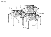
- FIG. 10.1 to FIG. 10.3 represent a further embodiment of the system according to the invention.
- the roof segments 16 of the systems are fastened together on the front sides (16.3) by means of a device.
- the system is, for example, a gutter construction 25.
- the systems can be freely combined, whereby systems of the same or different shape can be combined, since all systems contain central elements comprising central part 13, rafters 12 and roof segment 16.
- the systems can be interconnected in a simple manner since the system preferably consists of screw and / or plug connections. For attachment of the supports 11 of the system to a ground, ground sleeves 10 and pegs may be used.
Landscapes
- Engineering & Computer Science (AREA)
- Architecture (AREA)
- Civil Engineering (AREA)
- Structural Engineering (AREA)
- Roof Covering Using Slabs Or Stiff Sheets (AREA)
- Tents Or Canopies (AREA)
Priority Applications (1)
| Application Number | Priority Date | Filing Date | Title |
|---|---|---|---|
| EP09075259A EP2138654A3 (fr) | 2008-06-27 | 2009-06-08 | Abri |
Applications Claiming Priority (2)
| Application Number | Priority Date | Filing Date | Title |
|---|---|---|---|
| EP08075589 | 2008-06-27 | ||
| EP09075259A EP2138654A3 (fr) | 2008-06-27 | 2009-06-08 | Abri |
Publications (2)
| Publication Number | Publication Date |
|---|---|
| EP2138654A2 true EP2138654A2 (fr) | 2009-12-30 |
| EP2138654A3 EP2138654A3 (fr) | 2012-03-07 |
Family
ID=41078231
Family Applications (1)
| Application Number | Title | Priority Date | Filing Date |
|---|---|---|---|
| EP09075259A Withdrawn EP2138654A3 (fr) | 2008-06-27 | 2009-06-08 | Abri |
Country Status (2)
| Country | Link |
|---|---|
| EP (1) | EP2138654A3 (fr) |
| DE (1) | DE202009004903U1 (fr) |
Cited By (2)
| Publication number | Priority date | Publication date | Assignee | Title |
|---|---|---|---|---|
| CN112502467A (zh) * | 2020-12-07 | 2021-03-16 | 徐益锋 | 一种钢结构雨棚外力变化监控设备 |
| CN114376310A (zh) * | 2022-01-14 | 2022-04-22 | 福建优安纳伞业科技有限公司 | 一种雨天雨水观赏伞 |
Families Citing this family (3)
| Publication number | Priority date | Publication date | Assignee | Title |
|---|---|---|---|---|
| DE102018009830A1 (de) * | 2018-12-14 | 2020-06-18 | Cosmin Campean | Modulare Zeltanlage |
| CN214246855U (zh) * | 2020-12-10 | 2021-09-21 | 岁渡(厦门)休闲用品有限公司 | 一种新型帐篷 |
| DE202024107210U1 (de) | 2024-11-28 | 2025-01-16 | Gruwen Gmbh | Container mit Vordach |
Family Cites Families (1)
| Publication number | Priority date | Publication date | Assignee | Title |
|---|---|---|---|---|
| US4036244A (en) * | 1973-05-08 | 1977-07-19 | Tension Structures Co. | Vertical arch shelter |
-
2009
- 2009-06-08 DE DE200920004903 patent/DE202009004903U1/de not_active Expired - Lifetime
- 2009-06-08 EP EP09075259A patent/EP2138654A3/fr not_active Withdrawn
Cited By (3)
| Publication number | Priority date | Publication date | Assignee | Title |
|---|---|---|---|---|
| CN112502467A (zh) * | 2020-12-07 | 2021-03-16 | 徐益锋 | 一种钢结构雨棚外力变化监控设备 |
| CN114376310A (zh) * | 2022-01-14 | 2022-04-22 | 福建优安纳伞业科技有限公司 | 一种雨天雨水观赏伞 |
| CN114376310B (zh) * | 2022-01-14 | 2023-04-21 | 福建优安纳伞业科技有限公司 | 一种雨天雨水观赏伞 |
Also Published As
| Publication number | Publication date |
|---|---|
| EP2138654A3 (fr) | 2012-03-07 |
| DE202009004903U1 (de) | 2009-09-24 |
Similar Documents
| Publication | Publication Date | Title |
|---|---|---|
| EP3850749B1 (fr) | Système de toit solaire | |
| DE102009017337B4 (de) | Tragrahmen, Rahmengestell und damit gebauter Carport | |
| EP3755852B1 (fr) | Élément de clôture/balustrade/porte | |
| DE1784534A1 (de) | Dachhaut,insbesondere fuer Haengedaecher | |
| DE202009004903U1 (de) | Überdachung | |
| DE102022129981A1 (de) | Bausatz zur modularen Erweiterung von Carports, Dacherweiterungsmodul und Carport | |
| DE20109673U1 (de) | Mit Solarpanelen bestückte Lärmschutzwand | |
| EP2183448B1 (fr) | Abri pour voiture | |
| DE19524848C2 (de) | Modulare Freiflächenabdeckung | |
| DE202016003652U1 (de) | Vielseitig nutzbarer modularer System-Bausatz für ein bogenförmiges freitragendes Schutzdach für Personen und Sachen mit der Möglichkeit, solare Energie zu nutzen (Photovoltaik, Elektrospeicher, Lademöglichkeit und Beleuchtung) | |
| DE29616595U1 (de) | Unterstand | |
| DE102010012829A1 (de) | Transportabler Pavillon mit Regenrinne | |
| EP0838564B1 (fr) | Elément d'encadrement avec recouvrement flexible et bâtiment construit avec ces éléments d'encadrement | |
| EP0594069A1 (fr) | Caisse transportable et praticable | |
| DE19706567B4 (de) | Vordachsystem für Gebäudeeingänge | |
| DE10215165A1 (de) | Träger für Funktionseinheiten | |
| DE29904708U1 (de) | Universell einsetzbare Überdachung | |
| DE10022158A1 (de) | Überdachung einer langgestreckten Verkehrsfläche, insbesondere eines Bahnsteigs | |
| EP2672198A1 (fr) | Support de module solaire pour le montage de modules photovoltaïques comme modules intégrés | |
| DE202008014508U1 (de) | Schirmvorrichtung | |
| DE202024107210U1 (de) | Container mit Vordach | |
| DE202021104488U1 (de) | Zaunanlage | |
| DE202024101621U1 (de) | Freitragender Unterstand | |
| DE4138241A1 (de) | Zerlegbare halle, insbesondere fuer fernsprechstationen | |
| DE102024109327A1 (de) | Freitragender Unterstand |
Legal Events
| Date | Code | Title | Description |
|---|---|---|---|
| PUAI | Public reference made under article 153(3) epc to a published international application that has entered the european phase |
Free format text: ORIGINAL CODE: 0009012 |
|
| AK | Designated contracting states |
Kind code of ref document: A2 Designated state(s): AT BE BG CH CY CZ DE DK EE ES FI FR GB GR HR HU IE IS IT LI LT LU LV MC MK MT NL NO PL PT RO SE SI SK TR |
|
| PUAL | Search report despatched |
Free format text: ORIGINAL CODE: 0009013 |
|
| AK | Designated contracting states |
Kind code of ref document: A3 Designated state(s): AT BE BG CH CY CZ DE DK EE ES FI FR GB GR HR HU IE IS IT LI LT LU LV MC MK MT NL NO PL PT RO SE SI SK TR |
|
| AX | Request for extension of the european patent |
Extension state: AL BA RS |
|
| RIC1 | Information provided on ipc code assigned before grant |
Ipc: E04H 15/18 20060101ALI20120201BHEP Ipc: E04H 15/38 20060101AFI20120201BHEP |
|
| 17P | Request for examination filed |
Effective date: 20120403 |
|
| 17Q | First examination report despatched |
Effective date: 20120619 |
|
| STAA | Information on the status of an ep patent application or granted ep patent |
Free format text: STATUS: THE APPLICATION IS DEEMED TO BE WITHDRAWN |
|
| 18D | Application deemed to be withdrawn |
Effective date: 20140103 |