EP2138658A1 - Ferrure pour clapet de meuble - Google Patents
Ferrure pour clapet de meuble Download PDFInfo
- Publication number
- EP2138658A1 EP2138658A1 EP08011650A EP08011650A EP2138658A1 EP 2138658 A1 EP2138658 A1 EP 2138658A1 EP 08011650 A EP08011650 A EP 08011650A EP 08011650 A EP08011650 A EP 08011650A EP 2138658 A1 EP2138658 A1 EP 2138658A1
- Authority
- EP
- European Patent Office
- Prior art keywords
- flap
- pivot axis
- furniture
- side pivot
- axis
- Prior art date
- Legal status (The legal status is an assumption and is not a legal conclusion. Google has not performed a legal analysis and makes no representation as to the accuracy of the status listed.)
- Granted
Links
- 230000008878 coupling Effects 0.000 claims abstract description 11
- 238000010168 coupling process Methods 0.000 claims abstract description 11
- 238000005859 coupling reaction Methods 0.000 claims abstract description 11
- 230000001154 acute effect Effects 0.000 claims description 5
- 238000013016 damping Methods 0.000 claims description 4
- 230000007704 transition Effects 0.000 claims description 4
- 230000006835 compression Effects 0.000 claims 1
- 238000007906 compression Methods 0.000 claims 1
- 238000011161 development Methods 0.000 description 5
- 230000018109 developmental process Effects 0.000 description 5
- 230000033001 locomotion Effects 0.000 description 5
- 238000004146 energy storage Methods 0.000 description 1
- 238000004519 manufacturing process Methods 0.000 description 1
- 238000000034 method Methods 0.000 description 1
Images


Classifications
-
- E—FIXED CONSTRUCTIONS
- E05—LOCKS; KEYS; WINDOW OR DOOR FITTINGS; SAFES
- E05D—HINGES OR SUSPENSION DEVICES FOR DOORS, WINDOWS OR WINGS
- E05D15/00—Suspension arrangements for wings
- E05D15/40—Suspension arrangements for wings supported on arms movable in vertical planes
- E05D15/401—Suspension arrangements for wings supported on arms movable in vertical planes specially adapted for overhead wings
-
- E—FIXED CONSTRUCTIONS
- E05—LOCKS; KEYS; WINDOW OR DOOR FITTINGS; SAFES
- E05D—HINGES OR SUSPENSION DEVICES FOR DOORS, WINDOWS OR WINGS
- E05D15/00—Suspension arrangements for wings
- E05D15/40—Suspension arrangements for wings supported on arms movable in vertical planes
- E05D15/46—Suspension arrangements for wings supported on arms movable in vertical planes with two pairs of pivoted arms
- E05D15/463—Suspension arrangements for wings supported on arms movable in vertical planes with two pairs of pivoted arms specially adapted for overhead wings
-
- E—FIXED CONSTRUCTIONS
- E05—LOCKS; KEYS; WINDOW OR DOOR FITTINGS; SAFES
- E05D—HINGES OR SUSPENSION DEVICES FOR DOORS, WINDOWS OR WINGS
- E05D3/00—Hinges with pins
- E05D3/06—Hinges with pins with two or more pins
- E05D3/14—Hinges with pins with two or more pins with four parallel pins and two arms
-
- E—FIXED CONSTRUCTIONS
- E05—LOCKS; KEYS; WINDOW OR DOOR FITTINGS; SAFES
- E05F—DEVICES FOR MOVING WINGS INTO OPEN OR CLOSED POSITION; CHECKS FOR WINGS; WING FITTINGS NOT OTHERWISE PROVIDED FOR, CONCERNED WITH THE FUNCTIONING OF THE WING
- E05F1/00—Closers or openers for wings, not otherwise provided for in this subclass
- E05F1/08—Closers or openers for wings, not otherwise provided for in this subclass spring-actuated, e.g. for horizontally sliding wings
- E05F1/10—Closers or openers for wings, not otherwise provided for in this subclass spring-actuated, e.g. for horizontally sliding wings for swinging wings, e.g. counterbalance
- E05F1/12—Mechanisms in the shape of hinges or pivots, operated by springs
- E05F1/1246—Mechanisms in the shape of hinges or pivots, operated by springs with a coil spring perpendicular to the pivot axis
- E05F1/1269—Mechanisms in the shape of hinges or pivots, operated by springs with a coil spring perpendicular to the pivot axis with a traction spring
- E05F1/1276—Mechanisms in the shape of hinges or pivots, operated by springs with a coil spring perpendicular to the pivot axis with a traction spring for counterbalancing
-
- E—FIXED CONSTRUCTIONS
- E05—LOCKS; KEYS; WINDOW OR DOOR FITTINGS; SAFES
- E05F—DEVICES FOR MOVING WINGS INTO OPEN OR CLOSED POSITION; CHECKS FOR WINGS; WING FITTINGS NOT OTHERWISE PROVIDED FOR, CONCERNED WITH THE FUNCTIONING OF THE WING
- E05F1/00—Closers or openers for wings, not otherwise provided for in this subclass
- E05F1/08—Closers or openers for wings, not otherwise provided for in this subclass spring-actuated, e.g. for horizontally sliding wings
- E05F1/10—Closers or openers for wings, not otherwise provided for in this subclass spring-actuated, e.g. for horizontally sliding wings for swinging wings, e.g. counterbalance
- E05F1/14—Closers or openers for wings, not otherwise provided for in this subclass spring-actuated, e.g. for horizontally sliding wings for swinging wings, e.g. counterbalance with double-acting springs, e.g. for closing and opening or checking and closing no material
-
- E—FIXED CONSTRUCTIONS
- E05—LOCKS; KEYS; WINDOW OR DOOR FITTINGS; SAFES
- E05F—DEVICES FOR MOVING WINGS INTO OPEN OR CLOSED POSITION; CHECKS FOR WINGS; WING FITTINGS NOT OTHERWISE PROVIDED FOR, CONCERNED WITH THE FUNCTIONING OF THE WING
- E05F15/00—Power-operated mechanisms for wings
- E05F15/40—Safety devices, e.g. detection of obstructions or end positions
- E05F15/42—Detection using safety edges
- E05F2015/483—Detection using safety edges for detection during opening
-
- E—FIXED CONSTRUCTIONS
- E05—LOCKS; KEYS; WINDOW OR DOOR FITTINGS; SAFES
- E05Y—INDEXING SCHEME ASSOCIATED WITH SUBCLASSES E05D AND E05F, RELATING TO CONSTRUCTION ELEMENTS, ELECTRIC CONTROL, POWER SUPPLY, POWER SIGNAL OR TRANSMISSION, USER INTERFACES, MOUNTING OR COUPLING, DETAILS, ACCESSORIES, AUXILIARY OPERATIONS NOT OTHERWISE PROVIDED FOR, APPLICATION THEREOF
- E05Y2600/00—Mounting or coupling arrangements for elements provided for in this subclass
- E05Y2600/40—Mounting location; Visibility of the elements
- E05Y2600/41—Concealed
-
- E—FIXED CONSTRUCTIONS
- E05—LOCKS; KEYS; WINDOW OR DOOR FITTINGS; SAFES
- E05Y—INDEXING SCHEME ASSOCIATED WITH SUBCLASSES E05D AND E05F, RELATING TO CONSTRUCTION ELEMENTS, ELECTRIC CONTROL, POWER SUPPLY, POWER SIGNAL OR TRANSMISSION, USER INTERFACES, MOUNTING OR COUPLING, DETAILS, ACCESSORIES, AUXILIARY OPERATIONS NOT OTHERWISE PROVIDED FOR, APPLICATION THEREOF
- E05Y2900/00—Application of doors, windows, wings or fittings thereof
- E05Y2900/20—Application of doors, windows, wings or fittings thereof for furniture, e.g. cabinets
Definitions
- the invention relates to a flap fitting for a furniture flap, with a pivotable on the one hand on a furniture body about a fixed pivot axis and on the other hand on the furniture flap on a flap-side pivot axis movable actuator arm for moving the furniture flap between a cabinet compartment in the furniture body closing closed position and an upwardly moved open position, and with at least one control lever for controlling the angular position of the furniture flap with respect to the actuating arm, wherein the control lever is on the one hand articulated to a spaced from the flap-side pivot axis of the actuating arm flap-side pivot axis and on the other hand on a body-side pivot axis.
- a flap fitting of this kind is for example from the DE 20 2005 018 350 U1 known, in which case an actuating arm for moving the furniture flap is provided, which is pivotally mounted on the one hand to a body-side bearing axis and on the other hand to a flap-side bearing axis. Further, at least one eccentric to the actuator arm arranged additional control arm is provided, which is also articulated on the one hand on the furniture body and on the other hand articulated to a connected to the furniture flap flap-mounted part. If the actuator arm is combined with a single control arm, the flap is designed as a high-pivoting flap, ie the furniture flap pivots to the rear over the furniture body during the opening process.
- a four-bar linkage or parallelogram link is created by the control arms, which allows the use of the flap as a high-lift flap.
- the furniture flap moves over the entire opening or closing path substantially parallel to the front edge of the furniture body or to the level of a cupboard compartment opening.
- Furniture flaps with combined swing and lift kinematics can not be realized by the aforementioned actuator.
- the object of the invention is therefore to provide a flap fitting for a furniture flap of the type mentioned above, with respect to known from the prior art flap fittings as a result of an even more variable motion kinematics in the opening or closing movement an even wider scope of one with a such a moving furniture flap equipped cabinet can be realized.
- the flap fitting according to the invention for a furniture flap is characterized in that the body-side pivot axis is arranged on a bearing part which is storable about a fixed bearing axis on the furniture body and has a standing together with the body-side pivot axis of the control lever and the bearing axis in a triangular joint arrangement hinge axis, to a coupling member is arranged, on the other hand is coupled to a further hinge axis hinged to the actuator arm.
- the furniture flap can therefore initially stand a little way from the furniture body and is then guided upward in accordance with a lift movement, the furniture flap is only slightly oblique to the front edge of the furniture body. From a certain opening path, the flap then pivots away with its upper edge of the furniture body, so that it is aligned in the open position with the outside or decor side down.
- the furniture flap is inclined, for example, also substantially perpendicular to the level of the cupboard compartment opening. The furniture flap does not swing, as in a pure Hochschwenkklappe the case over the furniture body away to the rear, but it remains in front of the furniture body.
- furniture flaps equipped with the flap fitting according to the invention can also be used when no available space for the pivoted flap is present above the furniture body, which is usually the case with fitted kitchens.
- the flap fitting also allows avoiding the disadvantage of high lift flaps that the flap rises relatively high above the furniture body, which makes a pure high lift flap for use at a relatively close below the building ceiling arranged cupboard impossible.
- the furniture flap equipped by means of the flap fitting according to the invention does not protrude beyond the top of the cabinet compartment.
- the flap fitting according to the invention thus offers completely new fields of application for furniture flap.
- a connecting line runs between the flap-side pivot axis of the actuating arm and the flap-side pivot axis of the control lever in the mounted state of the flap fitting obliquely to a flap rear side of the furniture flap.
- the connecting line with the flap back includes an acute angle.
- the flap-side pivot axis of the actuating arm in the assembled state of the flap fitting is arranged closer to the flap rear side than the flap-side pivot axis of the control lever.
- the body-side pivot axis of the actuating arm in the mounted state of the flap fitting is substantially at the same height as the stationary bearing axis of the bearing part.
- the stationary bearing axis of the bearing part it would also be possible, in particular the stationary bearing axis of the bearing part farther back, so further away from the plane of the cupboard compartment opening to arrange.
- a spring device mounted in a stationary state on the one hand in the fitted state of the flap fitting and on the other hand mounted on one of the fitting components of the flap fitting, that in the closed position of the furniture flap a closing force directed in the closing direction is exerted on the furniture flap.
- This closing force must then be overcome first, when the flap is opened.
- the spring device is connected to the fitting components of the flap fitting so that when opening the furniture flap from a certain opening stroke an opening force in the direction Open position of the furniture flap is exercised.
- the flap weight when opening is at least partially compensated by the spring force of the spring.
- the spring device can be designed in such a way that the furniture flap automatically remains in its open position in any open position. From a certain dead center, which is expediently overcome after a short opening stroke of the furniture flap, then the opening force acting in the opening direction can be introduced to the furniture flap.
- the fitting-side articulation point of the spring device is located on the joint axis between the coupling member and the bearing part.
- the bearing part is designed as an angle lever, with two angularly arranged lever legs, at their respective free lever ends, the stationary bearing axis or the hinge axis sits, while in the connecting region of the two lever legs, the pivot axis is arranged.
- Such a bearing part is relatively easy and inexpensive to manufacture.
- the actuating arm has a body-side first arm portion, on the body-side pivot axis and other hinge axis are arranged, and a flap-side second arm portion on which the flap-side pivot axis is arranged on, wherein the two arm portions are connected to each other by means of a connecting portion in that the first arm section and second Arm section are arranged at an angle to each other.
- control lever it is possible for the control lever to have a body-side first lever section, on which the body-side pivot axis is seated, and a flap-side second lever section, on which the flap-side pivot axis is seated, which are interconnected via a transition section such that the first lever section and second lever section in FIG Are arranged angle to each other.
- a damping device for damping the furniture flap when entering the closed position and / or when starting the open position is provided.
- the Fig. 1 to 4 show a preferred embodiment of the flap fitting 11 of the invention.
- the flap fitting 11 is arranged on a cabinet, in particular wall unit, which is attached hanging in height on a building wall.
- a cabinet in particular wall unit, which is attached hanging in height on a building wall.
- the furniture body 12 of the cabinet has two opposite, vertical side walls 13, of which in the drawing only one is visible, a bottom wall 14, a ceiling wall 15 and a rear wall 16 and includes a limited by these walls cupboard 17.
- the front of the cabinet 17 is associated with a furniture flap 18, in its off Fig. 1 resulting closed position 19 assumes a vertical position and the cabinet compartment 17 closes.
- the furniture flap 18 has an outer or decorative side 20 and a rear side 21 opposite thereto.
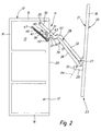
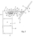
- the furniture flap 18 can move from the closed position 19 into an access position 22 (FIG. Fig. 4 ), wherein the opening movement on the in the Fig. 2 and 3 shown intermediate positions 23, 24 is carried upward. In the in Fig. 1 shown closed position, the furniture flap 18 is aligned parallel to the level of the cupboard opening 25.
- the flap fitting 11 which may also be referred to as a flap holder, has on the one hand on the furniture body 12 about a fixed pivot axis 26 and on the other hand on the furniture flap 18 on a flap-side pivot axis 27 pivotally mounted actuating arm 28 for moving the furniture flap between the cabinet compartment 17 closing position closed 19 and the upwardly moved open position 22nd
- the stationary pivot axis 26 of the actuating arm 28 is located not far below the top wall 15 of the furniture body 12. Conveniently, the stationary pivot axis 26 is seated on a fitting plate, not shown, which in turn is secured to the side wall 13 of the furniture body 12. In principle, however, it would also be possible to arrange the stationary pivot axis 26 directly on the side wall 13.
- the flap-side pivot axis 27 is seated on a holding part 29, which in turn is attached to the flap rear side 21 of the furniture flap 18.
- the actuator arm 28 has a body-side first arm portion 30, on which the stationary pivot axis 26 is arranged. On the body-side arm portion 30 is also a further hinge axis 31 which will be discussed in more detail below. Further, a flap-side second arm portion 32 is provided, on which the flap-side pivot axis 27 is arranged. The flap-side arm portion 32 is preferably longer than the body-side arm portion 30.
- the two arm portions 30, 32 are connected to each other via a connecting portion 33, such that the two arm portions 30, 32 are arranged at an angle to each other. As in particular in Fig. 1 1, the connecting portion 33 is curved, being arranged so as to be inclined forward from the body-side arm portion 30, with reference to FIG Fig.
- the flap-side arm portion 32 which in turn, as mentioned, is not parallel to the body side arm portion 30, but at an angle. If, therefore, the body-side arm section 30 were to be lengthened beyond the connecting section 33, then it encloses an acute angle with the flap-side arm section 32. It is characteristic that the flap-side arm section 32 extends in such a way that the end-side pivot-side pivot axis 27 lies on a connecting line with the further hinge axis 31 and the stationary pivot axis 26.
- the flap fitting 11 further comprises at least one control lever 34 for controlling the angular position of the furniture flap 18 with respect to the actuating arm 28 and with respect to the level of the cupboard compartment opening 25.
- the control lever 34 is on the one hand at a spaced from the flap-side pivot axis 27 of the actuating arm 28 flap-side pivot axis 35 and on the other hand hinged to a body-side pivot axis 36.
- the control lever 34 has a body-side first lever portion 37, on which the body-side pivot axis 36 is seated. Further, it has a flap-side second lever portion 38, on which the flap-side pivot axis 35 sits.
- the two lever sections 37, 38 are connected to each other via a transition section 39 such that the two lever sections 37, 38 are arranged at an angle to each other.
- the body-side lever portion 37 is designed to be relatively short.
- the transition section 39 which is exemplified in the form of an angle, that as in Fig. 1 shown jumps away from the short body-side lever section forward toward the rear flap.
- the flap-side lever portion 38 which is designed as a relatively long straight lever.
- at the end of the flap-side lever portion 38 is still a short substantially perpendicular to the lever longitudinal direction projecting projection may be provided on which then the body-side pivot axis 36 is arranged, which also sits on the holding part 29.
- the body-side pivot axis 36 of the control lever 34 is arranged on a bearing part 40 which is mounted on a stationary bearing axis 41 on the furniture body 12 and a standing together with the body-side pivot axis 36 of the control lever 34 and the bearing axis 41 in triangular articulation joint axis 42, at the a coupling member 43 is arranged, which is coupled on the other hand about the further hinge axis 31 pivotally connected to the actuating arm 28.
- a connecting line 44 between the flap-side pivot axis 27 and the flap-side pivot axis 35 in the assembled state of the flap fitting 11 at an acute angle to the rear flap 21st the furniture flap 18 extends.
- the flap-side pivot axis 27 of the actuating arm 28 is arranged closer to the flap rear side 21 than the flap-side pivot axis 35 of the control lever 34.
- body-side pivot axis 26 of the actuating arm 28 is arranged essentially at the same height as the stationary bearing axle 41 of the bearing part 40. Further, the body-side, fixed pivot axis 26 of the actuating arm 28 is above the stationary bearing axis 41 of the bearing part 40th
- the bearing part 40 is designed as an angle lever, wherein two angle arms arranged at an angle to each other 45a, 45b are provided, wherein at a free end of the lever, the stationary bearing axis 41 and at the other free end of the lever joint axis 42 sits.
- the body-side pivot axis 36 of the control lever 34 is arranged in the connecting region between the two lever arms 45a, 45b.
- the two lever arms 45a, 45b have substantially the same lever length.
- the spring device comprises at least one, in particular a single tension spring element.
- the articulation of the tension spring element on the joint axis 42 causes a closing force acting in the closing direction to be exerted on the furniture flap 18 in the closed position.
- an opening force can be exerted in the direction of the open position 22 of the furniture flap 18 from a certain opening distance.
- the Federanlenkddling 47 is located with respect to the fixed pivot axis 26 of the actuating arm 28 further back and further down.
- the furniture flap 18 is initially in accordance Fig. 1 in its closed position 19th actuating arm 28 and control lever 34 extend here within the furniture body 12 down.
- the actuating arm 28 is arranged in a different plane than the control lever 34, that is, the control lever 34 is located closer to the side wall 13 than the actuating arm arranged above it 28.
- the flap-side arm portion 32 of the actuating arm 28 is substantially aligned with the flap-side lever portion 38 of the control lever 34.
- the bearing member 40 assumes a position in which the one lever arm 45a extends substantially parallel to the body-side arm portion 30 of the actuating arm 28 while the other lever leg 45b directed towards the rear spring device 46 jumps away.
- the tension spring exerts a closing force acting on the furniture flap 18 in the closing direction.
- the furniture flap 18 enters the in Fig. 3 illustrated second intermediate position.
- the coupling member 43 has enclosed with the lying between the stationary pivot axis 26 and the other hinge axis 31 portion of the actuating arm 28 an obtuse angle is now formed between these two parts an acute angle.
- the actuating arm 28 has already reached its substantially uppermost position, in which the body-side arm portion 30 substantially is aligned parallel to the ceiling wall 15.
- the tension spring element causes the flap weight is partially or completely compensated.
- the furniture flap 18 enters the in Fig. 4 shown open position 22.
- the furniture flap 18 was opposite to in Fig. 3 shown second intermediate position further pivoted clockwise, so that now the decorative page 20 shows down.
- the actuating arm 28 was no longer pivoted about its stationary pivot axis 26 relative to the second intermediate position.
- the control lever 34 has pivoted a little further, so that it has reached substantially the height of the ceiling wall 15 of the furniture body 12. This further pivoting of the control lever causes the furniture flap 18 from the in Fig. 3 shown relatively steep position, in which it projects beyond the Dekkenwand 15 of the furniture body 12, in the relatively flat, the horizontal approximated position is pivoted on. In this position, the furniture flap 18 is no longer on the ceiling wall 15 of the furniture body 12 also.
Landscapes
- Engineering & Computer Science (AREA)
- Mechanical Engineering (AREA)
- Hinges (AREA)
- Pivots And Pivotal Connections (AREA)
Priority Applications (2)
| Application Number | Priority Date | Filing Date | Title |
|---|---|---|---|
| AT08011650T ATE522691T1 (de) | 2008-06-27 | 2008-06-27 | Klappenbeschlag für eine möbelklappe |
| EP08011650A EP2138658B1 (fr) | 2008-06-27 | 2008-06-27 | Ferrure pour volet de meuble |
Applications Claiming Priority (1)
| Application Number | Priority Date | Filing Date | Title |
|---|---|---|---|
| EP08011650A EP2138658B1 (fr) | 2008-06-27 | 2008-06-27 | Ferrure pour volet de meuble |
Publications (2)
| Publication Number | Publication Date |
|---|---|
| EP2138658A1 true EP2138658A1 (fr) | 2009-12-30 |
| EP2138658B1 EP2138658B1 (fr) | 2011-08-31 |
Family
ID=39884832
Family Applications (1)
| Application Number | Title | Priority Date | Filing Date |
|---|---|---|---|
| EP08011650A Not-in-force EP2138658B1 (fr) | 2008-06-27 | 2008-06-27 | Ferrure pour volet de meuble |
Country Status (2)
| Country | Link |
|---|---|
| EP (1) | EP2138658B1 (fr) |
| AT (1) | ATE522691T1 (fr) |
Cited By (2)
| Publication number | Priority date | Publication date | Assignee | Title |
|---|---|---|---|---|
| WO2019007760A1 (fr) * | 2017-07-03 | 2019-01-10 | Hettich-Oni Gmbh & Co. Kg | Ferrure d'abattant et meuble |
| US20230258032A1 (en) * | 2020-10-22 | 2023-08-17 | Julius Blum Gmbh | Furniture fitting comprising a multi-joint mechanism |
Families Citing this family (2)
| Publication number | Priority date | Publication date | Assignee | Title |
|---|---|---|---|---|
| DE102017114776A1 (de) | 2017-07-03 | 2019-01-03 | Hettich-Oni Gmbh & Co. Kg | Dämpferanordnung und Klappenbeschlag |
| DE102017114774A1 (de) | 2017-07-03 | 2019-01-03 | Hettich-Oni Gmbh & Co. Kg | Klappenbeschlag und Möbel |
Citations (3)
| Publication number | Priority date | Publication date | Assignee | Title |
|---|---|---|---|---|
| DE202005016375U1 (de) * | 2005-10-13 | 2005-12-22 | Hetal-Werke Franz Hettich Gmbh & Co. Kg | Beschlag zum schwenkbaren Befestigen einer Frontklappe an einem Möbelschrank |
| DE202005018350U1 (de) | 2004-12-03 | 2006-01-12 | Julius Blum Gmbh | Stellantrieb zum Bewegen einer Möbelklappe |
| EP1785567A2 (fr) * | 2005-11-10 | 2007-05-16 | Hetal-Werke Franz Hettich GmbH & Co. KG | Ferrure pour un volet de meuble |
-
2008
- 2008-06-27 AT AT08011650T patent/ATE522691T1/de active
- 2008-06-27 EP EP08011650A patent/EP2138658B1/fr not_active Not-in-force
Patent Citations (3)
| Publication number | Priority date | Publication date | Assignee | Title |
|---|---|---|---|---|
| DE202005018350U1 (de) | 2004-12-03 | 2006-01-12 | Julius Blum Gmbh | Stellantrieb zum Bewegen einer Möbelklappe |
| DE202005016375U1 (de) * | 2005-10-13 | 2005-12-22 | Hetal-Werke Franz Hettich Gmbh & Co. Kg | Beschlag zum schwenkbaren Befestigen einer Frontklappe an einem Möbelschrank |
| EP1785567A2 (fr) * | 2005-11-10 | 2007-05-16 | Hetal-Werke Franz Hettich GmbH & Co. KG | Ferrure pour un volet de meuble |
Cited By (4)
| Publication number | Priority date | Publication date | Assignee | Title |
|---|---|---|---|---|
| WO2019007760A1 (fr) * | 2017-07-03 | 2019-01-10 | Hettich-Oni Gmbh & Co. Kg | Ferrure d'abattant et meuble |
| US11053723B2 (en) | 2017-07-03 | 2021-07-06 | Hettich-Oni Gmbh & Co. Kg | Flap fitting and item of furniture |
| RU2763183C2 (ru) * | 2017-07-03 | 2021-12-28 | ХЕТТИХ-ОНИ ГмбХ унд Ко. КГ | Фурнитура створки и предмет мебели |
| US20230258032A1 (en) * | 2020-10-22 | 2023-08-17 | Julius Blum Gmbh | Furniture fitting comprising a multi-joint mechanism |
Also Published As
| Publication number | Publication date |
|---|---|
| EP2138658B1 (fr) | 2011-08-31 |
| ATE522691T1 (de) | 2011-09-15 |
Similar Documents
| Publication | Publication Date | Title |
|---|---|---|
| EP3612700B1 (fr) | Paroi de meuble avec un clapet et un corps de meuble et meuble avec une telle paroi de meuble | |
| EP3198097B1 (fr) | Charnière pour meubles | |
| AT516783B1 (de) | Stützvorrichtung für eine Möbelklappe | |
| DE69801325T2 (de) | Verbesserte gelenkvorrichtung eines an einer kraftfahrzeugkarosserie schwenkbar angeordneten flügels | |
| EP1818491B1 (fr) | Ferrure pour un volet de meuble | |
| DE10019337C2 (de) | Klappenhalter | |
| EP3198096B1 (fr) | Charnière de meuble | |
| WO2015154842A1 (fr) | Dispositif déflecteur arrière pour un véhicule | |
| EP2268882A1 (fr) | Charnière de meuble | |
| DE102004019785B4 (de) | Klappenbeschlag | |
| AT527779B1 (de) | Möbel mit einem Möbelkorpus und einer geführten Klappe | |
| DE10203269A1 (de) | Beschlagvorrichtung für eine Möbelklappe | |
| EP2138658B1 (fr) | Ferrure pour volet de meuble | |
| AT508071A1 (de) | Möbelscharnier | |
| EP1785567A2 (fr) | Ferrure pour un volet de meuble | |
| DE102011085177B4 (de) | Antriebssystem für ein KFZ-Dachsystem | |
| WO2022082235A1 (fr) | Accessoire de meuble comprenant un mécanisme à articulations multiples | |
| DE10117769B4 (de) | Vorrichtung zur Unterstützung einer Öffnungsbewegung einer Fahrzeugklappe | |
| EP1835107B1 (fr) | Support de volet pour un volet de meuble | |
| EP3737816B1 (fr) | Charnière de meuble, panneau de meuble et corps de meuble | |
| DE202005018350U1 (de) | Stellantrieb zum Bewegen einer Möbelklappe | |
| DE202004020900U1 (de) | Klappenbeschlag | |
| DE10018732A1 (de) | Auswerfervorrichtung für eine Klappenanordnung, insbesondere eine Kraftfahrzeug-Heckklappenanordnung | |
| DE10143922A1 (de) | Scharnier | |
| DE10114658B4 (de) | Vorrichtung zum Begrenzen einer Öffnungsbewegung einer Schranktür, insbesondere einer Klapptür |
Legal Events
| Date | Code | Title | Description |
|---|---|---|---|
| PUAI | Public reference made under article 153(3) epc to a published international application that has entered the european phase |
Free format text: ORIGINAL CODE: 0009012 |
|
| 17P | Request for examination filed |
Effective date: 20090411 |
|
| AK | Designated contracting states |
Kind code of ref document: A1 Designated state(s): AT BE BG CH CY CZ DE DK EE ES FI FR GB GR HR HU IE IS IT LI LT LU LV MC MT NL NO PL PT RO SE SI SK TR |
|
| AX | Request for extension of the european patent |
Extension state: AL BA MK RS |
|
| AKX | Designation fees paid |
Designated state(s): AT DE IT |
|
| REG | Reference to a national code |
Ref country code: DE Ref legal event code: R079 Ref document number: 502008004644 Country of ref document: DE Free format text: PREVIOUS MAIN CLASS: E05D0003060000 Ipc: E05D0015460000 |
|
| RIC1 | Information provided on ipc code assigned before grant |
Ipc: E05D 15/46 20060101AFI20110211BHEP |
|
| RTI1 | Title (correction) |
Free format text: FITTING FOR A FURNITURE FLAP |
|
| GRAP | Despatch of communication of intention to grant a patent |
Free format text: ORIGINAL CODE: EPIDOSNIGR1 |
|
| GRAS | Grant fee paid |
Free format text: ORIGINAL CODE: EPIDOSNIGR3 |
|
| GRAA | (expected) grant |
Free format text: ORIGINAL CODE: 0009210 |
|
| AK | Designated contracting states |
Kind code of ref document: B1 Designated state(s): AT DE IT |
|
| REG | Reference to a national code |
Ref country code: DE Ref legal event code: R096 Ref document number: 502008004644 Country of ref document: DE Effective date: 20111027 |
|
| PLBE | No opposition filed within time limit |
Free format text: ORIGINAL CODE: 0009261 |
|
| STAA | Information on the status of an ep patent application or granted ep patent |
Free format text: STATUS: NO OPPOSITION FILED WITHIN TIME LIMIT |
|
| 26N | No opposition filed |
Effective date: 20120601 |
|
| REG | Reference to a national code |
Ref country code: DE Ref legal event code: R097 Ref document number: 502008004644 Country of ref document: DE Effective date: 20120601 |
|
| PGFP | Annual fee paid to national office [announced via postgrant information from national office to epo] |
Ref country code: AT Payment date: 20140611 Year of fee payment: 7 Ref country code: DE Payment date: 20140619 Year of fee payment: 7 Ref country code: IT Payment date: 20140625 Year of fee payment: 7 |
|
| REG | Reference to a national code |
Ref country code: DE Ref legal event code: R119 Ref document number: 502008004644 Country of ref document: DE |
|
| PG25 | Lapsed in a contracting state [announced via postgrant information from national office to epo] |
Ref country code: IT Free format text: LAPSE BECAUSE OF NON-PAYMENT OF DUE FEES Effective date: 20150627 |
|
| REG | Reference to a national code |
Ref country code: AT Ref legal event code: MM01 Ref document number: 522691 Country of ref document: AT Kind code of ref document: T Effective date: 20150627 |
|
| PG25 | Lapsed in a contracting state [announced via postgrant information from national office to epo] |
Ref country code: DE Free format text: LAPSE BECAUSE OF NON-PAYMENT OF DUE FEES Effective date: 20160101 |
|
| PG25 | Lapsed in a contracting state [announced via postgrant information from national office to epo] |
Ref country code: AT Free format text: LAPSE BECAUSE OF NON-PAYMENT OF DUE FEES Effective date: 20150627 |