EP2138693A1 - Procédé pour déterminer la quantité de particules accumulées dans un filtre à particules - Google Patents
Procédé pour déterminer la quantité de particules accumulées dans un filtre à particules Download PDFInfo
- Publication number
- EP2138693A1 EP2138693A1 EP08425448A EP08425448A EP2138693A1 EP 2138693 A1 EP2138693 A1 EP 2138693A1 EP 08425448 A EP08425448 A EP 08425448A EP 08425448 A EP08425448 A EP 08425448A EP 2138693 A1 EP2138693 A1 EP 2138693A1
- Authority
- EP
- European Patent Office
- Prior art keywords
- particulate
- amount
- particulate filter
- calculated
- accumulated
- Prior art date
- Legal status (The legal status is an assumption and is not a legal conclusion. Google has not performed a legal analysis and makes no representation as to the accuracy of the status listed.)
- Granted
Links
Images




Classifications
-
- F—MECHANICAL ENGINEERING; LIGHTING; HEATING; WEAPONS; BLASTING
- F02—COMBUSTION ENGINES; HOT-GAS OR COMBUSTION-PRODUCT ENGINE PLANTS
- F02D—CONTROLLING COMBUSTION ENGINES
- F02D41/00—Electrical control of supply of combustible mixture or its constituents
- F02D41/22—Safety or indicating devices for abnormal conditions
-
- F—MECHANICAL ENGINEERING; LIGHTING; HEATING; WEAPONS; BLASTING
- F01—MACHINES OR ENGINES IN GENERAL; ENGINE PLANTS IN GENERAL; STEAM ENGINES
- F01N—GAS-FLOW SILENCERS OR EXHAUST APPARATUS FOR MACHINES OR ENGINES IN GENERAL; GAS-FLOW SILENCERS OR EXHAUST APPARATUS FOR INTERNAL-COMBUSTION ENGINES
- F01N13/00—Exhaust or silencing apparatus characterised by constructional features
- F01N13/009—Exhaust or silencing apparatus characterised by constructional features having two or more separate purifying devices arranged in series
- F01N13/0097—Exhaust or silencing apparatus characterised by constructional features having two or more separate purifying devices arranged in series the purifying devices are arranged in a single housing
-
- F—MECHANICAL ENGINEERING; LIGHTING; HEATING; WEAPONS; BLASTING
- F01—MACHINES OR ENGINES IN GENERAL; ENGINE PLANTS IN GENERAL; STEAM ENGINES
- F01N—GAS-FLOW SILENCERS OR EXHAUST APPARATUS FOR MACHINES OR ENGINES IN GENERAL; GAS-FLOW SILENCERS OR EXHAUST APPARATUS FOR INTERNAL-COMBUSTION ENGINES
- F01N3/00—Exhaust or silencing apparatus having means for purifying, rendering innocuous, or otherwise treating exhaust
- F01N3/02—Exhaust or silencing apparatus having means for purifying, rendering innocuous, or otherwise treating exhaust for cooling, or for removing solid constituents of, exhaust
- F01N3/021—Exhaust or silencing apparatus having means for purifying, rendering innocuous, or otherwise treating exhaust for cooling, or for removing solid constituents of, exhaust by means of filters
- F01N3/023—Exhaust or silencing apparatus having means for purifying, rendering innocuous, or otherwise treating exhaust for cooling, or for removing solid constituents of, exhaust by means of filters using means for regenerating the filters, e.g. by burning trapped particles
-
- F—MECHANICAL ENGINEERING; LIGHTING; HEATING; WEAPONS; BLASTING
- F01—MACHINES OR ENGINES IN GENERAL; ENGINE PLANTS IN GENERAL; STEAM ENGINES
- F01N—GAS-FLOW SILENCERS OR EXHAUST APPARATUS FOR MACHINES OR ENGINES IN GENERAL; GAS-FLOW SILENCERS OR EXHAUST APPARATUS FOR INTERNAL-COMBUSTION ENGINES
- F01N3/00—Exhaust or silencing apparatus having means for purifying, rendering innocuous, or otherwise treating exhaust
- F01N3/02—Exhaust or silencing apparatus having means for purifying, rendering innocuous, or otherwise treating exhaust for cooling, or for removing solid constituents of, exhaust
- F01N3/021—Exhaust or silencing apparatus having means for purifying, rendering innocuous, or otherwise treating exhaust for cooling, or for removing solid constituents of, exhaust by means of filters
- F01N3/033—Exhaust or silencing apparatus having means for purifying, rendering innocuous, or otherwise treating exhaust for cooling, or for removing solid constituents of, exhaust by means of filters in combination with other devices
- F01N3/035—Exhaust or silencing apparatus having means for purifying, rendering innocuous, or otherwise treating exhaust for cooling, or for removing solid constituents of, exhaust by means of filters in combination with other devices with catalytic reactors
-
- F—MECHANICAL ENGINEERING; LIGHTING; HEATING; WEAPONS; BLASTING
- F01—MACHINES OR ENGINES IN GENERAL; ENGINE PLANTS IN GENERAL; STEAM ENGINES
- F01N—GAS-FLOW SILENCERS OR EXHAUST APPARATUS FOR MACHINES OR ENGINES IN GENERAL; GAS-FLOW SILENCERS OR EXHAUST APPARATUS FOR INTERNAL-COMBUSTION ENGINES
- F01N9/00—Electrical control of exhaust gas treating apparatus
- F01N9/002—Electrical control of exhaust gas treating apparatus of filter regeneration
-
- F—MECHANICAL ENGINEERING; LIGHTING; HEATING; WEAPONS; BLASTING
- F01—MACHINES OR ENGINES IN GENERAL; ENGINE PLANTS IN GENERAL; STEAM ENGINES
- F01N—GAS-FLOW SILENCERS OR EXHAUST APPARATUS FOR MACHINES OR ENGINES IN GENERAL; GAS-FLOW SILENCERS OR EXHAUST APPARATUS FOR INTERNAL-COMBUSTION ENGINES
- F01N9/00—Electrical control of exhaust gas treating apparatus
- F01N9/005—Electrical control of exhaust gas treating apparatus using models instead of sensors to determine operating characteristics of exhaust systems, e.g. calculating catalyst temperature instead of measuring it directly
-
- F—MECHANICAL ENGINEERING; LIGHTING; HEATING; WEAPONS; BLASTING
- F01—MACHINES OR ENGINES IN GENERAL; ENGINE PLANTS IN GENERAL; STEAM ENGINES
- F01N—GAS-FLOW SILENCERS OR EXHAUST APPARATUS FOR MACHINES OR ENGINES IN GENERAL; GAS-FLOW SILENCERS OR EXHAUST APPARATUS FOR INTERNAL-COMBUSTION ENGINES
- F01N2900/00—Details of electrical control or of the monitoring of the exhaust gas treating apparatus
- F01N2900/06—Parameters used for exhaust control or diagnosing
- F01N2900/16—Parameters used for exhaust control or diagnosing said parameters being related to the exhaust apparatus, e.g. particulate filter or catalyst
- F01N2900/1606—Particle filter loading or soot amount
-
- F—MECHANICAL ENGINEERING; LIGHTING; HEATING; WEAPONS; BLASTING
- F02—COMBUSTION ENGINES; HOT-GAS OR COMBUSTION-PRODUCT ENGINE PLANTS
- F02D—CONTROLLING COMBUSTION ENGINES
- F02D2200/00—Input parameters for engine control
- F02D2200/02—Input parameters for engine control the parameters being related to the engine
- F02D2200/08—Exhaust gas treatment apparatus parameters
- F02D2200/0812—Particle filter loading
-
- F—MECHANICAL ENGINEERING; LIGHTING; HEATING; WEAPONS; BLASTING
- F02—COMBUSTION ENGINES; HOT-GAS OR COMBUSTION-PRODUCT ENGINE PLANTS
- F02D—CONTROLLING COMBUSTION ENGINES
- F02D41/00—Electrical control of supply of combustible mixture or its constituents
- F02D41/02—Circuit arrangements for generating control signals
- F02D41/021—Introducing corrections for particular conditions exterior to the engine
- F02D41/0235—Introducing corrections for particular conditions exterior to the engine in relation with the state of the exhaust gas treating apparatus
- F02D41/027—Introducing corrections for particular conditions exterior to the engine in relation with the state of the exhaust gas treating apparatus to purge or regenerate the exhaust gas treating apparatus
- F02D41/029—Introducing corrections for particular conditions exterior to the engine in relation with the state of the exhaust gas treating apparatus to purge or regenerate the exhaust gas treating apparatus the exhaust gas treating apparatus being a particulate filter
-
- Y—GENERAL TAGGING OF NEW TECHNOLOGICAL DEVELOPMENTS; GENERAL TAGGING OF CROSS-SECTIONAL TECHNOLOGIES SPANNING OVER SEVERAL SECTIONS OF THE IPC; TECHNICAL SUBJECTS COVERED BY FORMER USPC CROSS-REFERENCE ART COLLECTIONS [XRACs] AND DIGESTS
- Y02—TECHNOLOGIES OR APPLICATIONS FOR MITIGATION OR ADAPTATION AGAINST CLIMATE CHANGE
- Y02T—CLIMATE CHANGE MITIGATION TECHNOLOGIES RELATED TO TRANSPORTATION
- Y02T10/00—Road transport of goods or passengers
- Y02T10/10—Internal combustion engine [ICE] based vehicles
- Y02T10/40—Engine management systems
Definitions
- the present invention relates to a method for determining the amount of particulate that has accumulated in a particulate filter.
- the present invention finds advantageous, though non-exclusive, application in the engine sector, particularly in internal-combustion engines of motor vehicles, and amongst these principally in diesel engines, to which the ensuing treatment will make explicit reference, without this implying any loss of generality.
- diesel engines of motor vehicles emit exhaust gases that are highly pollutant, given that they contain nitrogen oxides (NOx) and particulate, i.e., unburnt particles constituted principally by carbon material.
- NOx nitrogen oxides
- particulate i.e., unburnt particles constituted principally by carbon material.
- numerous countries are introducing increasingly stringent limits to exhaust-gas emissions by internal-combustion engines in order to reduce atmospheric pollution. Consequently, the reduction of the particulate present in exhaust gases constitutes one of the targets required by future European standards on pollutant emissions (Euro5, Euro5+, and Euro6 standards).
- particulate filter also known as particulate trap
- oxidizing catalytic converter which is set upstream of the particulate filter and has the function of promoting complete oxidation of exhaust gases, converting unburnt hydrocarbons, nitrogen oxides, and carbon monoxide into dioxide carbon, water, and nitrogen.
- the functions of the oxidizing catalytic converter and of the particulate filter can be alternatively performed by a single component known as catalysed particulate filter.
- the internal-combustion engine 22 is of the supercharged type and comprises a turbosupercharger 23 formed by a compressor 24 set along an air-intake pipe 25 and by a turbine 26 coupled to the compressor 24 and set along an exhaust pipe 27.
- the system for discharge of the gases 21 is provided with a system for post-treatment 21b of the exhaust gases, comprising a catalysed particulate filter, i.e., comprising: an oxidizing catalytic converter 28, set along the exhaust pipe 27 in a position close to the turbosupercharger 23, and a particulate filter 29 set along the exhaust pipe 27, downstream of the oxidizing catalytic converter 28; and a further oxidizing catalytic converter 28b set along the exhaust pipe 27, upstream of the particulate filter 29.
- a catalysed particulate filter i.e., comprising: an oxidizing catalytic converter 28, set along the exhaust pipe 27 in a position close to the turbosupercharger 23, and a particulate filter 29 set along the exhaust pipe 27, downstream of the oxidizing catalytic converter 28; and a further oxidizing catalytic converter 28b set along the exhaust pipe 27, upstream of the particulate filter 29.
- the discharge system 21 is moreover provided with: an electronic-control system 31 comprising an airflow meter (debimeter) 32, set along the air-intake pipe 25 and generating an electrical signal indicating the flowrate of the air in the air-intake pipe 25 itself; a differential-pressure sensor 33 having a first input and a second input connected to the input and to the output, respectively, of the catalysed particulate filter, and an output supplying an electrical signal indicating the drop in pressure across the catalysed particulate filter; a first temperature sensor 34 set at output from the particulate filter 29 and supplying an electrical signal indicating the temperature of the exhaust gases at outlet from the particulate filter 29; a second temperature sensor 35 set on the inlet of the particulate filter 29 and supplying an electrical signal indicating the temperature of the exhaust gases at inlet of the particulate filter 29; an atmospheric-pressure sensor 36; and an electronic control unit 37 connected to the aforementioned sensors and configured for determining the amount of particulate that has accumulated in the particulate filter 29 and
- the particulate filter 29 has the function of mechanical barrier for the passage of the particulate and is in general constituted by parallel channels with porous walls and alternately obstructed.
- the obstructions force the exhaust gases to traverse the side walls of the channels so that the unburnt particles constituting the particulate are first withheld in the porosities of the side walls themselves and then, when the latter are completely filled, accumulate on the internal surfaces of the walls of the channels to form a porous layer.
- the pressure drop on the particulate filter increases, and hence the counterpressure generated by the particulate filter itself.
- the particulate cannot hence be accumulated indefinitely because high accumulations cause:
- the regenerations can broadly speaking be distinguished into active regenerations, i.e., ones controlled by an electronic control unit, and spontaneous regenerations, i.e., ones triggered in an uncontrolled and unforeseeable way during a phase of accumulation, typically caused by the presence of high accumulations of nitrogen dioxide (NO 2 ).
- active regenerations i.e., ones controlled by an electronic control unit
- spontaneous regenerations i.e., ones triggered in an uncontrolled and unforeseeable way during a phase of accumulation, typically caused by the presence of high accumulations of nitrogen dioxide (NO 2 ).
- NO 2 nitrogen dioxide
- phase of accumulation i.e., time intervals in which there is a progressive accumulation of particulate in the particulate filter and there is no active regeneration, at most spontaneous regenerations, and regeneration phases, i.e., time intervals in which active regeneration occurs and the amount of particulate accumulated in the particulate filter decreases.
- the active regeneration of the particulate filter is obtained by means of the combustion (oxidation) of the particulate accumulated, which, since it is made up prevalently of carbon, reacts with the oxygen present in the exhaust gases, being transformed into carbon monoxide (CO) and carbon dioxide (CO 2 ).
- CO carbon monoxide
- CO 2 carbon dioxide
- the temperature of the exhaust gases at inlet to the particulate filter should be raised artificially until self-ignition of the combustion of the particulate is obtained, i.e., occurrence of the regeneration is obtained.
- the artificial rise in temperature of the exhaust gases is advantageously obtained by using a post injection of fuel performed in the cylinders of the internal-combustion engine following upon the main fuel injection.
- the post injection of fuel can be alternatively carried out either during the expansion phase, in such a way that the injected fuel will burn in the combustion chamber, thus raising the temperature of the exhaust gases produced by the internal-combustion engine, or else during the exhaust phase, in such a way that the injected fuel will not burn in the combustion chamber and will reach unburnt the oxidizing catalytic converter, thus giving rise to an exothermal reaction that raises the temperature of the exhaust gases produced by the internal-combustion engine.
- the statistical models are based upon a collection, carried out infield and with experimental tests, of data regarding the performance of a plurality of particulate filters in a wide field of engine operating conditions, for example when it is idling, in conditions of city traffic, out-of-town traffic and motorway traffic, and in conditions of high torque and high power.
- the data gathered enable creation of a statistics of the accumulation of particulate within the particulate filter as the time and the engine point vary.
- Said in-field collection of data makes it possible to map each individual engine point with a corresponding rate of accumulation of particulate inside the particulate filter, expressed as mass of particulate accumulated per unit time (PM[g/h]).
- the amount of particulate that has accumulated in the particulate filter at a given instant is then obtained as summation of the products of the rates of accumulation for the various engine points and the time that has effectively elapsed in said engine points.
- Physical models envisage, instead, calculation of the amount of particulate that has accumulated in the particulate filter on the basis of a set of data, such as the counterpressure of the particulate filter, i.e., the difference between the pressure downstream and the pressure upstream of the particulate filter, the volume flowrate of exhaust gases and the temperature of the exhaust gases.
- the four experimental operating parameters ⁇ , ⁇ , ⁇ , ⁇ are determined experimentally by carrying out a specific set of bench tests with engine in steady-state running conditions.
- the operating parameter ⁇ is not kept constant, but rather it is mapped as a function of the different engine operating conditions, i.e., as a function of particular stationary conditions of accumulation of the particulate.
- initially determined and stored in the form of a map are a plurality of reference values ⁇ PDPF of a parameter ⁇ defining a relation between the amount of particulate m s that has accumulated in the particulate filter and the drop in pressure ⁇ P DPF on the particulate filter itself, each of the reference values ⁇ PDPF being associated to a respective steady-state condition of operation of the engine in which particulate accumulates in the particulate filter itself.
- an operating value ⁇ MOD of the parameter ⁇ as a function of the reference value ⁇ PDPF of the parameter ⁇ itself for the same steady-state operating condition of the engine, and the history of accumulation of particulate in the particulate filter, i.e., the history of the engine points in which the engine itself has worked in the period that has elapsed from the last regeneration.
- Said operating value ⁇ MOD of the parameter ⁇ is used for calculating the amount of particulate that has accumulated in the particulate filter and triggering regeneration thereof.
- Physical models enable estimation of the amount of particulate that has accumulated on the basis of known quantities, which are generally determined with the aid of sensors connected to an electronic control unit, such as air-intake flowrate sensors (debimeters), temperature sensors at input to the particulate filter, and differential pressure sensors, designed to measure the counterpressure generated by the particulate filter.
- sensors connected to an electronic control unit, such as air-intake flowrate sensors (debimeters), temperature sensors at input to the particulate filter, and differential pressure sensors, designed to measure the counterpressure generated by the particulate filter.
- the aforementioned sensors may be subject to malfunctioning, both electrical (drifts, variations of offset and/or gain, etc.) and mechanical (clogging, accumulation of dirt, etc.), with the consequence that the measurements provided by them may be imprecise.
- any malfunctioning is difficult to diagnose so that it can happen that the estimation of the amount of particulate that has accumulated, in so far as it depends upon the measurements supplied by the sensors, is erroneous.
- the regeneration would be activated even though there is no effective need therefor, causing a dilution of the oil for lubrication of the internal-combustion engine and a consequent risk as regards operation thereof.
- the hybrid model guarantees that regeneration will not occur before a minimum or maximum Telec interval has elapsed from the previous regeneration, thus preventing an excessive dilution of the lubricating oil.
- both the hybrid model and the physical model described previously present certain critical aspects in specific situations, such as turning-off of the engine, and spontaneous regenerations and deliberately interrupted active regenerations, during which they are unable to model the phenomenon of accumulation of particulate in the particulate filter in a sufficiently precise way.
- the aim of the present invention is hence to provide a method for determining the amount of particulate that has accumulated in a particulate filter that will mitigate at least in part the drawbacks of the known art.
- a method for determining the amount of particulate that has accumulated in a particulate filter is provided, as defined in the annexed claims.
- the present invention stems from the assumption that, during an accumulation step and in the absence of spontaneous regenerations, the amount of particulate that has accumulated in the particulate filter increases over time so that any estimate thereof must respect a law of minimum increment.
- a spontaneous regeneration takes place, the amount of particulate that has accumulated in the particulate filter is reduced, but with a rate of reduction not higher than a maximum admissible rate.
- This further assumption is based on observations made by the present applicant, who has noted how, during a spontaneous regeneration, there generally occurs a decrease in the resistance to flow to which there does not correspond a real decrease in the amount of particulate.
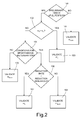
- the present method is implemented by the electronic control unit provided for determining the amount of particulate that has accumulated in the particulate filter and for activating regeneration thereof, which operates on a discrete-time base and at each calculation step performs the operations described hereinafter with reference to Figure 2 and to Figures 3-6 , in which represented with a solid line are the plots of the calculated particulate amounts m s , whilst represented with dashed-and-dotted lines are the plots of the validated particulate amounts m sv .
- the electronic control unit preliminarily checks (block 100) whether there are given operating conditions that cause the aforesaid measured and/or determined physical quantities, namely, the counterpressure ⁇ P of the particulate filter and the volume flowrate Q v and the resistance resflow to the flow of the exhaust gases through the particulate filter, depending upon which is the calculated particulate amount m s , to be reliable. Specifically, said reliability is verified if the counterpressure ⁇ P of the particulate filter and the volume flowrate Q v and the resistance resflow to the flow of the exhaust gases through the particulate filter are greater than or equal to respective reliability thresholds defined in a step of calibration of the system.
- the calculated particulate amount m s is not validated, and in its place a substitutive particulate amount m subst is validated, obtained by incrementing the validated particulate amount m sv for the previous calculation step with a substitution increase rate ⁇ + mapped as a function of the driving profile of the motor vehicle on which the discharge system is mounted.
- the electronic control unit checks (block 102) whether the calculated particulate amount m s is greater than or equal to the previous validated particulate amount m sv .
- the calculated particulate amount m s is validated (block 103). If, instead, the calculated particulate amount m s is lower than the previous validated particulate amount m sv , this indicates a reduction in the amount of particulate that has accumulated in the particulate filter during the accumulation, therefore the electronic control unit checks (block 104) whether there are operating conditions that could give rise to a spontaneous regeneration of the particulate filter, this being the only condition that could justify said reduction.
- the electronic control unit checks (block 106) whether the rate of reduction of the calculated particulate amount is less than a given reduction threshold (represented with a dashed line). If it is ( Figure 5a ), then the reduction of the calculated particulate amount is compatible with the one that can be obtained with a spontaneous regeneration of the particulate filter, therefore the calculated particulate amount m s is validated (block 107).
- the validation process depends upon the conditions in which the reduction of the calculated particulate amount m s has occurred, namely:
- Figure 6 illustrates, by way of example, the validation process in the various situations described above.
- Figure 6 illustrates the plots of the calculated particulate amounts m s (solid line), obtained by using the physical model, and of the corresponding validated particulate amounts m sv (dashed-and-dotted lines), obtained by applying a time-continuous version of the present method, i.e., assuming a calculation step of infinitesimal amplitude.
- Figure 6 moreover illustrates a step of active regeneration of duration T ar and a subsequent initialization step T g .
- the control unit restarts execution of the validation method described only after a transient period represented by the initialization step T g .
- the physical model on the basis of which the amount of particulate that has accumulated in the particulate filter is calculated is modified in the way described hereinafter in order to improve significantly the performance thereof.
- the new physical model advantageously enables a further increase in the reliability of the calculation of the amount of particulate that has accumulated in the particulate filter.
- the value of the calibration coefficient ⁇ is not constant, but it is markedly affected by the amount of particulate that has accumulated in the particulate filter and by the motor-vehicle driving profile during the accumulation step, therefore it is not possible to approximate with just one value of the calibration coefficient ⁇ all the possible modes of accumulation of the particulate in the particulate filter.
- Eq. (7) requires the knowledge of an initial value or constant of integration, which represents the amount of particulate present in the particulate filter at the instant of start of the integration, in the example described above at the end of the aforesaid guard interval Tg; this value can be conveniently calculated using the previous point equation (6).
- the initialization step Tg comprises a guard interval T g1 and a subsequent wait interval T g2 .
- the electronic control unit simply validates (dashed-and-dotted line) substitutive particulate amounts m subst (dashed line), obtained by incrementing previously validated substitutive particulate amounts m subst with the substitution increase rate ⁇ + , starting from an initial value m 0 determined statistically and indicating the residual amount of particulate normally still present in the particulate filter at the end of a regeneration.
- the control unit calculates, in addition to the substitutive amounts of particulate m subst , which continue to be validated, amounts m s of particulate (solid line), calculated on the basis of a point physical model, for example, by implementing Eq. (6), i.e., a physical model that does not require any initialization.
- the calculated particulate amounts m s present an evolution decreasing in time until an instant T min , following upon which they present an increasing evolution.
- the control unit initialises the integral physical model, using as initial value the amount m s of particulate calculated with the point model; next, the control unit calculates the amount m s of particulate that has accumulated on the basis of the integral physical model (solid line, subsequent to the instant T g2 ), and subjects it to validation in the way described previously, i.e., compares it with the validated particulate amount m sv for the previous calculation step.
- the control unit compares the amount m s of particulate calculated at the instant T min with the corresponding substitutive particulate amount m subst . In the case where the amount m s of particulate calculated at the instant T min is greater than the corresponding substitutive particulate amount m subst ( Figure 7b ), the control unit validates the calculated particulate amount m s and initialises the integral physical model to said value, proceeding to calculation of validated particulate amounts m sv as described previously.
- Said calculated particulate amount m s is hence assumed as initial value of the integral physical model.
- Eq. (7) is implemented by the electronic control unit on a time-discrete basis as a summation of products, the factors of which are constituted by the value of the calibration coefficient ⁇ and of the resistance resflow to the flow of the exhaust gases through the particulate filter at the current calculation step.
- the resistance resflow to the flow of the exhaust gases through the particulate filter is defined as the ratio between the counterpressure ⁇ P of the particulate filter and the volume flowrate Q v of the exhaust gases through the particulate filter, whilst the calibration coefficient ⁇ is determined experimentally.
- the calibration coefficient ⁇ is mapped as a function of the amount of particulate that has accumulated in the particulate filter and of the motor-vehicle driving profile (city traffic, out-of-town traffic, motorway traffic, etc.), the latter being determined on the basis of the speed of the motor vehicle, the gear engaged and the engine running conditions and load, and being then corrected as a function of the temperature T GAS and the volume flowrate Q v of the exhaust gases, as well as of the amount of ashes of the lubricating oil that have accumulated in the particulate filter (which reduce the useful volume of the particulate filter as if there had accumulated a further amount of particulate, with consequent variation of the counterpressure) according to experimental criteria.
- the motor-vehicle driving profile city traffic, out-of-town traffic, motorway traffic, etc.
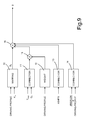
- the electronic control unit executes a software program that implements a system for determining the amount m s of particulate that has accumulated in the particulate filter, the block diagram of which is illustrated in Figure 8 .
- the determination system designated as a whole by 1, comprises:
- block 3 for determining the calibration coefficient ⁇ in turn comprises:
- the validated particulate amounts m sv supplied by block 8 are subjected to a further validation step implementing a threshold-check mechanism of the type described in the aforesaid European patent EP 1541829 filed in the name of the present applicant; i.e., they are further compared with corresponding minimum and maximum values, which define a corresponding range of admissibility and are obtained on the basis of the estimates supplied by a statistical model.
- this amount of particulate is definitively validated; otherwise, it is limited to the aforementioned maximum or minimum values in the cases where the validated particulate amount exceeds the maximum value or is less than the minimum value, respectively.
- the amount m s of particulate that has accumulated in the particulate filter could be calculated, instead of on the basis of Eq. (7), also on the basis of one of Eqs. (3), (5) and (6), even though, as has been said previously, the combination of the validation method described above with Eq. (7) enables better results to be obtained in terms of reliability and precision of the determination of the amount of particulate that has accumulated in the particulate filter.
- the calibration coefficient ⁇ could be calculated in a way different from what has been described previously, for example, in the way described in the aforesaid European patent EP 1333165 filed in the name of the present applicant.
Landscapes
- Engineering & Computer Science (AREA)
- Chemical & Material Sciences (AREA)
- Combustion & Propulsion (AREA)
- Mechanical Engineering (AREA)
- General Engineering & Computer Science (AREA)
- Chemical Kinetics & Catalysis (AREA)
- Analytical Chemistry (AREA)
- Processes For Solid Components From Exhaust (AREA)
- Filtering Of Dispersed Particles In Gases (AREA)
- Exhaust Gas After Treatment (AREA)
- Exhaust Gas Treatment By Means Of Catalyst (AREA)
- Sampling And Sample Adjustment (AREA)
Priority Applications (5)
| Application Number | Priority Date | Filing Date | Title |
|---|---|---|---|
| EP08425448A EP2138693B1 (fr) | 2008-06-25 | 2008-06-25 | Procédé pour déterminer la quantité de particules accumulées dans un filtre à particules |
| AT08425448T ATE496208T1 (de) | 2008-06-25 | 2008-06-25 | Verfahren zur bestimmung der menge von in einem partikelfilter angesammelten partikel |
| DE602008004638T DE602008004638D1 (de) | 2008-06-25 | 2008-06-25 | Verfahren zur Bestimmung der Menge von in einem Partikelfilter angesammelten Partikel |
| US12/491,175 US8413429B2 (en) | 2008-06-25 | 2009-06-24 | Method for determining the amount of particulate accumulated in a particulate filter |
| JP2009149632A JP5292199B2 (ja) | 2008-06-25 | 2009-06-24 | 微粒子フィルタに蓄積した微粒子の量の算出方法 |
Applications Claiming Priority (1)
| Application Number | Priority Date | Filing Date | Title |
|---|---|---|---|
| EP08425448A EP2138693B1 (fr) | 2008-06-25 | 2008-06-25 | Procédé pour déterminer la quantité de particules accumulées dans un filtre à particules |
Publications (2)
| Publication Number | Publication Date |
|---|---|
| EP2138693A1 true EP2138693A1 (fr) | 2009-12-30 |
| EP2138693B1 EP2138693B1 (fr) | 2011-01-19 |
Family
ID=39941442
Family Applications (1)
| Application Number | Title | Priority Date | Filing Date |
|---|---|---|---|
| EP08425448A Not-in-force EP2138693B1 (fr) | 2008-06-25 | 2008-06-25 | Procédé pour déterminer la quantité de particules accumulées dans un filtre à particules |
Country Status (5)
| Country | Link |
|---|---|
| US (1) | US8413429B2 (fr) |
| EP (1) | EP2138693B1 (fr) |
| JP (1) | JP5292199B2 (fr) |
| AT (1) | ATE496208T1 (fr) |
| DE (1) | DE602008004638D1 (fr) |
Cited By (6)
| Publication number | Priority date | Publication date | Assignee | Title |
|---|---|---|---|---|
| FR2989422A1 (fr) * | 2012-04-13 | 2013-10-18 | Peugeot Citroen Automobiles Sa | Procede de calcul d'une masse de suies presentes dans un filtre a particules |
| GB2513586A (en) * | 2013-04-30 | 2014-11-05 | Gm Global Tech Operations Inc | Method of controlling a diesel particulate filter |
| CN106812576A (zh) * | 2015-12-02 | 2017-06-09 | 康明斯排放处理公司 | 在空载或低负载期间的碳烟负载估计 |
| CN110005509A (zh) * | 2018-01-05 | 2019-07-12 | 罗伯特·博世有限公司 | 用于检测柴油颗粒物过滤器捕获的颗粒物量的方法和系统 |
| IT201800000951A1 (it) * | 2018-01-15 | 2019-07-15 | Magneti Marelli Spa | Metodo per controllare la portata di particolato in uscita da un filtro antiparticolato per un motore a combustione interna |
| WO2020043965A1 (fr) * | 2018-08-30 | 2020-03-05 | Psa Automobiles Sa | Procede de correction d'une estimation de charge en suies d'un filtre a particules lors d'une baisse de sa contre-pression |
Families Citing this family (15)
| Publication number | Priority date | Publication date | Assignee | Title |
|---|---|---|---|---|
| US7739895B2 (en) * | 2007-12-12 | 2010-06-22 | Spx Corporation | Verification of scale calibration method and apparatus |
| US20110000193A1 (en) * | 2009-07-02 | 2011-01-06 | Woodward Governor Company | System and method for detecting diesel particulate filter conditions based on thermal response thereof |
| JP5630894B2 (ja) * | 2010-02-05 | 2014-11-26 | 株式会社堀場製作所 | 粒子状物質計測装置 |
| US8484955B2 (en) * | 2011-02-04 | 2013-07-16 | GM Global Technology Operations LLC | System and method for estimating an amount of particulate matter accumulated in a particulate filter |
| DE102011108445A1 (de) * | 2011-07-23 | 2013-01-24 | Volkswagen Aktiengesellschaft | Messverfahren und Messanordnung für Verunreinigungen der Ladeluft eines Abgasturboladers |
| US9091190B2 (en) * | 2012-08-01 | 2015-07-28 | GM Global Technology Operations LLC | Accumulated ash correction during soot mass estimation in a vehicle exhaust aftertreatment device |
| JP2015169137A (ja) | 2014-03-07 | 2015-09-28 | トヨタ自動車株式会社 | 内燃機関の排気浄化装置 |
| US9169766B2 (en) * | 2014-03-18 | 2015-10-27 | GM Global Technology Operations LLC | System to monitor regeneration frequency of particulate filter |
| EP2963271B1 (fr) * | 2014-06-18 | 2017-01-11 | Fiat Group Automobiles S.p.A. | Système et procédé pour estimer la quantité de particules accumulées dans le filtre à particules d'un moteur diesel |
| JP6358101B2 (ja) * | 2015-01-13 | 2018-07-18 | 株式会社デンソー | 異常診断装置 |
| US10294846B2 (en) * | 2016-08-31 | 2019-05-21 | Ge Global Sourcing Llc | Systems for vehicle particulate filter regeneration |
| WO2018160259A1 (fr) | 2017-03-03 | 2018-09-07 | Halliburton Energy Services, Inc. | Additifs de fluide de forage marqués chimiquement |
| IT201800002311A1 (it) * | 2018-02-01 | 2019-08-01 | Magneti Marelli Spa | Metodo per determinare la quantita' di polveri metalliche accumulate in un filtro antiparticolato per un motore a combustione interna |
| DE102018114779B4 (de) * | 2018-06-20 | 2020-07-30 | Dr. Ing. H.C. F. Porsche Aktiengesellschaft | Verfahren zur Bestimmung des Beladungszustands eines Partikelfilters eines Kraftfahrzeugs |
| JP2023175088A (ja) * | 2022-05-30 | 2023-12-12 | 株式会社Subaru | 車両の排気系触媒の管理装置 |
Citations (6)
| Publication number | Priority date | Publication date | Assignee | Title |
|---|---|---|---|---|
| EP1333165A1 (fr) | 2002-01-25 | 2003-08-06 | C.R.F. Società Consortile per Azioni | Méthode pour déterminer la quantité des particules accumulée dans un filtre à particules |
| FR2862342A1 (fr) * | 2003-11-19 | 2005-05-20 | Renault Sas | Procede et systeme d'estimation de quantites de particules emises dans les gaz d'echappement d'un moteur diesel d'un vehicule automobile |
| EP1541829A1 (fr) | 2003-12-12 | 2005-06-15 | C.R.F. Società Consortile per Azioni | Procédé d'activation de régénération d'un filtre à particules à base de l'estimation de la quantité des particules accumulées dans le filtre à particules |
| FR2888617A1 (fr) * | 2005-07-12 | 2007-01-19 | Peugeot Citroen Automobiles Sa | Systeme de determination de la quantite de suies brulee lors de la regeneration d'un filtre a particules |
| EP1762718A2 (fr) * | 2005-09-09 | 2007-03-14 | Delphi Technologies, Inc. | Procédé de régénération d'un filtre à particules |
| FR2902467A1 (fr) * | 2006-06-19 | 2007-12-21 | Renault Sas | Systeme de regulation de la pression de suralimentation d'un moteur et procede de regulation |
Family Cites Families (13)
| Publication number | Priority date | Publication date | Assignee | Title |
|---|---|---|---|---|
| GB2239407B (en) * | 1989-12-27 | 1994-10-12 | Nissan Motor | Exhaust gas purifying device for an internal combustion engine |
| JP3918649B2 (ja) | 2002-06-14 | 2007-05-23 | 株式会社デンソー | 内燃機関の排気ガス浄化装置 |
| JP4403961B2 (ja) * | 2004-03-12 | 2010-01-27 | 株式会社デンソー | 内燃機関の排気浄化装置 |
| JP2005307880A (ja) | 2004-04-22 | 2005-11-04 | Toyota Motor Corp | 排気浄化用フィルタの差圧センサ異常検出装置 |
| CN100491704C (zh) * | 2004-08-10 | 2009-05-27 | 日产自动车株式会社 | 柴油机微粒滤清器中微粒沉积量的推算装置及方法 |
| JP4463726B2 (ja) * | 2005-05-13 | 2010-05-19 | 本田技研工業株式会社 | パティキュレート堆積量算出装置 |
| US7263825B1 (en) * | 2005-09-15 | 2007-09-04 | Cummins, Inc. | Apparatus, system, and method for detecting and labeling a filter regeneration event |
| US7677032B2 (en) * | 2005-09-15 | 2010-03-16 | Cummins, Inc. | Apparatus, system, and method for determining the distribution of particulate matter on a particulate filter |
| US7587892B2 (en) * | 2005-12-13 | 2009-09-15 | Cummins Ip, Inc | Apparatus, system, and method for adapting a filter regeneration profile |
| ATE477405T1 (de) * | 2006-06-28 | 2010-08-15 | Fiat Ricerche | Regeneration eines dieselpartikelfilters |
| US7698888B2 (en) * | 2007-02-06 | 2010-04-20 | International Engine Intellectual Property Company, Llc | System and method for calculating loading of a diesel particulate filter by windowing inputs |
| US7870779B2 (en) * | 2007-04-24 | 2011-01-18 | Thermo King Corporation | Structure and method to verify diesel particulate filter operation |
| KR100969370B1 (ko) * | 2007-12-14 | 2010-07-09 | 현대자동차주식회사 | 매연여과장치의 유효체적 계산 방법 |
-
2008
- 2008-06-25 DE DE602008004638T patent/DE602008004638D1/de active Active
- 2008-06-25 AT AT08425448T patent/ATE496208T1/de not_active IP Right Cessation
- 2008-06-25 EP EP08425448A patent/EP2138693B1/fr not_active Not-in-force
-
2009
- 2009-06-24 JP JP2009149632A patent/JP5292199B2/ja not_active Expired - Fee Related
- 2009-06-24 US US12/491,175 patent/US8413429B2/en not_active Expired - Fee Related
Patent Citations (6)
| Publication number | Priority date | Publication date | Assignee | Title |
|---|---|---|---|---|
| EP1333165A1 (fr) | 2002-01-25 | 2003-08-06 | C.R.F. Società Consortile per Azioni | Méthode pour déterminer la quantité des particules accumulée dans un filtre à particules |
| FR2862342A1 (fr) * | 2003-11-19 | 2005-05-20 | Renault Sas | Procede et systeme d'estimation de quantites de particules emises dans les gaz d'echappement d'un moteur diesel d'un vehicule automobile |
| EP1541829A1 (fr) | 2003-12-12 | 2005-06-15 | C.R.F. Società Consortile per Azioni | Procédé d'activation de régénération d'un filtre à particules à base de l'estimation de la quantité des particules accumulées dans le filtre à particules |
| FR2888617A1 (fr) * | 2005-07-12 | 2007-01-19 | Peugeot Citroen Automobiles Sa | Systeme de determination de la quantite de suies brulee lors de la regeneration d'un filtre a particules |
| EP1762718A2 (fr) * | 2005-09-09 | 2007-03-14 | Delphi Technologies, Inc. | Procédé de régénération d'un filtre à particules |
| FR2902467A1 (fr) * | 2006-06-19 | 2007-12-21 | Renault Sas | Systeme de regulation de la pression de suralimentation d'un moteur et procede de regulation |
Non-Patent Citations (2)
| Title |
|---|
| KLADOPOULOU E A ET AL: "A Study Describing the Performance of Diesel Particulate Filters During Loading and Regeneration - A Lumped Parameter Model for Control Applications", SAE WORLD CONGRESS, XX, XX, no. SAE-2003-01-0842, 3 March 2003 (2003-03-03), XP002328841 * |
| KONSTANDOPOULOS A. G. ET AL.: "Fundamental Studies of diesel Particulate Filters: Transient Loading, Regeneration and Ageing", SAE 2000-01-1016, 2000 |
Cited By (11)
| Publication number | Priority date | Publication date | Assignee | Title |
|---|---|---|---|---|
| FR2989422A1 (fr) * | 2012-04-13 | 2013-10-18 | Peugeot Citroen Automobiles Sa | Procede de calcul d'une masse de suies presentes dans un filtre a particules |
| GB2513586A (en) * | 2013-04-30 | 2014-11-05 | Gm Global Tech Operations Inc | Method of controlling a diesel particulate filter |
| CN106812576A (zh) * | 2015-12-02 | 2017-06-09 | 康明斯排放处理公司 | 在空载或低负载期间的碳烟负载估计 |
| US10273858B2 (en) | 2015-12-02 | 2019-04-30 | Cummins Emission Solutions Inc. | Soot load estimation during idle or low load |
| CN106812576B (zh) * | 2015-12-02 | 2019-11-08 | 康明斯排放处理公司 | 在空载或低负载期间估计碳烟负载的系统、方法和装置 |
| US10781739B2 (en) | 2015-12-02 | 2020-09-22 | Cummins Emission Solutions Inc. | Soot load estimation during idle or low load |
| CN110005509A (zh) * | 2018-01-05 | 2019-07-12 | 罗伯特·博世有限公司 | 用于检测柴油颗粒物过滤器捕获的颗粒物量的方法和系统 |
| IT201800000951A1 (it) * | 2018-01-15 | 2019-07-15 | Magneti Marelli Spa | Metodo per controllare la portata di particolato in uscita da un filtro antiparticolato per un motore a combustione interna |
| EP3511542A1 (fr) * | 2018-01-15 | 2019-07-17 | Magneti Marelli S.p.A. | Procédé de contrôle de la quantité de particules sortant d'un filtre à particules d'un moteur à combustion interne |
| WO2020043965A1 (fr) * | 2018-08-30 | 2020-03-05 | Psa Automobiles Sa | Procede de correction d'une estimation de charge en suies d'un filtre a particules lors d'une baisse de sa contre-pression |
| FR3085426A1 (fr) * | 2018-08-30 | 2020-03-06 | Psa Automobiles Sa | Procede de correction d’une estimation de charge en suies d’un filtre a particules lors d’une baisse de sa contre-pression |
Also Published As
| Publication number | Publication date |
|---|---|
| ATE496208T1 (de) | 2011-02-15 |
| EP2138693B1 (fr) | 2011-01-19 |
| JP5292199B2 (ja) | 2013-09-18 |
| JP2010031853A (ja) | 2010-02-12 |
| US8413429B2 (en) | 2013-04-09 |
| US20090320452A1 (en) | 2009-12-31 |
| DE602008004638D1 (de) | 2011-03-03 |
Similar Documents
| Publication | Publication Date | Title |
|---|---|---|
| EP2138693B1 (fr) | Procédé pour déterminer la quantité de particules accumulées dans un filtre à particules | |
| EP1333165B1 (fr) | Méthode pour déterminer la quantité des particules accumulées dans un filtre à particules | |
| US6758039B2 (en) | Exhaust gas cleaning system having particulate filter | |
| JP4513593B2 (ja) | 内燃機関の排気ガス浄化装置 | |
| US7065960B2 (en) | Method for activation of the regeneration of a particulate filter based on an estimate of the quantity of particulate accumulated in the particulate filter | |
| US6962046B2 (en) | Exhaust gas cleaning system having particulate filter | |
| EP1766205B1 (fr) | Procede permettant de determiner une anomalie dans un filtre a particules | |
| EP2551479B1 (fr) | Appareil de détection de problème pour un filtre à particules | |
| EP2394034B1 (fr) | Diagnostic embarqué de véhicule d'un catalyseur d'oxydation | |
| US7152392B2 (en) | Exhaust gas cleaning system for internal combustion engine | |
| US20040200271A1 (en) | Pressure sensor diagnosis via a computer | |
| JP4403944B2 (ja) | 内燃機関の排気浄化装置 | |
| CN110107386B (zh) | 用于确定适于内燃发动机的微粒过滤器中积聚的金属粉末量的方法 | |
| CN112161743A (zh) | Dpf压差传感器的测量值可信性的评估方法及柴油机 | |
| JP4308702B2 (ja) | 排気浄化装置 | |
| EP1900928A1 (fr) | Système de purification de gaz d échappement d un moteur à combustion interne | |
| US8745972B2 (en) | Exhaust purification system of internal combustion engine | |
| JP4863111B2 (ja) | 排気浄化装置 | |
| US20070157818A1 (en) | System for evaluating the charge state of an exhaust line depollution means | |
| US20070256408A1 (en) | Particulate Matter Remaining Amount Estimating Method for Particulate Filter and Particulate Filter Regenerating Method | |
| JP4259944B2 (ja) | 微粒子フィルタに蓄積された微粒子の量を決定する方法 | |
| JP4739377B2 (ja) | 微粒子フィルタに蓄積された微粒子の量を決定する方法 |
Legal Events
| Date | Code | Title | Description |
|---|---|---|---|
| PUAI | Public reference made under article 153(3) epc to a published international application that has entered the european phase |
Free format text: ORIGINAL CODE: 0009012 |
|
| 17P | Request for examination filed |
Effective date: 20090713 |
|
| AK | Designated contracting states |
Kind code of ref document: A1 Designated state(s): AT BE BG CH CY CZ DE DK EE ES FI FR GB GR HR HU IE IS IT LI LT LU LV MC MT NL NO PL PT RO SE SI SK TR |
|
| AX | Request for extension of the european patent |
Extension state: AL BA MK RS |
|
| GRAP | Despatch of communication of intention to grant a patent |
Free format text: ORIGINAL CODE: EPIDOSNIGR1 |
|
| AKX | Designation fees paid |
Designated state(s): AT BE BG CH CY CZ DE DK EE ES FI FR GB GR HR HU IE IS IT LI LT LU LV MC MT NL NO PL PT RO SE SI SK TR |
|
| GRAS | Grant fee paid |
Free format text: ORIGINAL CODE: EPIDOSNIGR3 |
|
| RIN1 | Information on inventor provided before grant (corrected) |
Inventor name: TONETTI, MARCO Inventor name: GIOANNINI, ALBERTO |
|
| GRAA | (expected) grant |
Free format text: ORIGINAL CODE: 0009210 |
|
| AK | Designated contracting states |
Kind code of ref document: B1 Designated state(s): AT BE BG CH CY CZ DE DK EE ES FI FR GB GR HR HU IE IS IT LI LT LU LV MC MT NL NO PL PT RO SE SI SK TR |
|
| REG | Reference to a national code |
Ref country code: GB Ref legal event code: FG4D |
|
| REG | Reference to a national code |
Ref country code: CH Ref legal event code: EP |
|
| REG | Reference to a national code |
Ref country code: IE Ref legal event code: FG4D |
|
| REF | Corresponds to: |
Ref document number: 602008004638 Country of ref document: DE Date of ref document: 20110303 Kind code of ref document: P |
|
| REG | Reference to a national code |
Ref country code: DE Ref legal event code: R096 Ref document number: 602008004638 Country of ref document: DE Effective date: 20110303 |
|
| REG | Reference to a national code |
Ref country code: NL Ref legal event code: VDEP Effective date: 20110119 |
|
| LTIE | Lt: invalidation of european patent or patent extension |
Effective date: 20110119 |
|
| PG25 | Lapsed in a contracting state [announced via postgrant information from national office to epo] |
Ref country code: SE Free format text: LAPSE BECAUSE OF FAILURE TO SUBMIT A TRANSLATION OF THE DESCRIPTION OR TO PAY THE FEE WITHIN THE PRESCRIBED TIME-LIMIT Effective date: 20110119 Ref country code: LT Free format text: LAPSE BECAUSE OF FAILURE TO SUBMIT A TRANSLATION OF THE DESCRIPTION OR TO PAY THE FEE WITHIN THE PRESCRIBED TIME-LIMIT Effective date: 20110119 Ref country code: HR Free format text: LAPSE BECAUSE OF FAILURE TO SUBMIT A TRANSLATION OF THE DESCRIPTION OR TO PAY THE FEE WITHIN THE PRESCRIBED TIME-LIMIT Effective date: 20110119 Ref country code: ES Free format text: LAPSE BECAUSE OF FAILURE TO SUBMIT A TRANSLATION OF THE DESCRIPTION OR TO PAY THE FEE WITHIN THE PRESCRIBED TIME-LIMIT Effective date: 20110430 Ref country code: IS Free format text: LAPSE BECAUSE OF FAILURE TO SUBMIT A TRANSLATION OF THE DESCRIPTION OR TO PAY THE FEE WITHIN THE PRESCRIBED TIME-LIMIT Effective date: 20110519 Ref country code: PT Free format text: LAPSE BECAUSE OF FAILURE TO SUBMIT A TRANSLATION OF THE DESCRIPTION OR TO PAY THE FEE WITHIN THE PRESCRIBED TIME-LIMIT Effective date: 20110519 Ref country code: NO Free format text: LAPSE BECAUSE OF FAILURE TO SUBMIT A TRANSLATION OF THE DESCRIPTION OR TO PAY THE FEE WITHIN THE PRESCRIBED TIME-LIMIT Effective date: 20110419 Ref country code: LV Free format text: LAPSE BECAUSE OF FAILURE TO SUBMIT A TRANSLATION OF THE DESCRIPTION OR TO PAY THE FEE WITHIN THE PRESCRIBED TIME-LIMIT Effective date: 20110119 Ref country code: GR Free format text: LAPSE BECAUSE OF FAILURE TO SUBMIT A TRANSLATION OF THE DESCRIPTION OR TO PAY THE FEE WITHIN THE PRESCRIBED TIME-LIMIT Effective date: 20110420 |
|
| PG25 | Lapsed in a contracting state [announced via postgrant information from national office to epo] |
Ref country code: PL Free format text: LAPSE BECAUSE OF FAILURE TO SUBMIT A TRANSLATION OF THE DESCRIPTION OR TO PAY THE FEE WITHIN THE PRESCRIBED TIME-LIMIT Effective date: 20110119 Ref country code: SI Free format text: LAPSE BECAUSE OF FAILURE TO SUBMIT A TRANSLATION OF THE DESCRIPTION OR TO PAY THE FEE WITHIN THE PRESCRIBED TIME-LIMIT Effective date: 20110119 Ref country code: AT Free format text: LAPSE BECAUSE OF FAILURE TO SUBMIT A TRANSLATION OF THE DESCRIPTION OR TO PAY THE FEE WITHIN THE PRESCRIBED TIME-LIMIT Effective date: 20110119 Ref country code: BE Free format text: LAPSE BECAUSE OF FAILURE TO SUBMIT A TRANSLATION OF THE DESCRIPTION OR TO PAY THE FEE WITHIN THE PRESCRIBED TIME-LIMIT Effective date: 20110119 Ref country code: BG Free format text: LAPSE BECAUSE OF FAILURE TO SUBMIT A TRANSLATION OF THE DESCRIPTION OR TO PAY THE FEE WITHIN THE PRESCRIBED TIME-LIMIT Effective date: 20110419 Ref country code: FI Free format text: LAPSE BECAUSE OF FAILURE TO SUBMIT A TRANSLATION OF THE DESCRIPTION OR TO PAY THE FEE WITHIN THE PRESCRIBED TIME-LIMIT Effective date: 20110119 Ref country code: CY Free format text: LAPSE BECAUSE OF FAILURE TO SUBMIT A TRANSLATION OF THE DESCRIPTION OR TO PAY THE FEE WITHIN THE PRESCRIBED TIME-LIMIT Effective date: 20110119 Ref country code: NL Free format text: LAPSE BECAUSE OF FAILURE TO SUBMIT A TRANSLATION OF THE DESCRIPTION OR TO PAY THE FEE WITHIN THE PRESCRIBED TIME-LIMIT Effective date: 20110119 |
|
| PG25 | Lapsed in a contracting state [announced via postgrant information from national office to epo] |
Ref country code: EE Free format text: LAPSE BECAUSE OF FAILURE TO SUBMIT A TRANSLATION OF THE DESCRIPTION OR TO PAY THE FEE WITHIN THE PRESCRIBED TIME-LIMIT Effective date: 20110119 Ref country code: DK Free format text: LAPSE BECAUSE OF FAILURE TO SUBMIT A TRANSLATION OF THE DESCRIPTION OR TO PAY THE FEE WITHIN THE PRESCRIBED TIME-LIMIT Effective date: 20110119 |
|
| PLBE | No opposition filed within time limit |
Free format text: ORIGINAL CODE: 0009261 |
|
| STAA | Information on the status of an ep patent application or granted ep patent |
Free format text: STATUS: NO OPPOSITION FILED WITHIN TIME LIMIT |
|
| PG25 | Lapsed in a contracting state [announced via postgrant information from national office to epo] |
Ref country code: CZ Free format text: LAPSE BECAUSE OF FAILURE TO SUBMIT A TRANSLATION OF THE DESCRIPTION OR TO PAY THE FEE WITHIN THE PRESCRIBED TIME-LIMIT Effective date: 20110119 Ref country code: SK Free format text: LAPSE BECAUSE OF FAILURE TO SUBMIT A TRANSLATION OF THE DESCRIPTION OR TO PAY THE FEE WITHIN THE PRESCRIBED TIME-LIMIT Effective date: 20110119 Ref country code: RO Free format text: LAPSE BECAUSE OF FAILURE TO SUBMIT A TRANSLATION OF THE DESCRIPTION OR TO PAY THE FEE WITHIN THE PRESCRIBED TIME-LIMIT Effective date: 20110119 |
|
| 26N | No opposition filed |
Effective date: 20111020 |
|
| PG25 | Lapsed in a contracting state [announced via postgrant information from national office to epo] |
Ref country code: MT Free format text: LAPSE BECAUSE OF FAILURE TO SUBMIT A TRANSLATION OF THE DESCRIPTION OR TO PAY THE FEE WITHIN THE PRESCRIBED TIME-LIMIT Effective date: 20110119 |
|
| REG | Reference to a national code |
Ref country code: DE Ref legal event code: R097 Ref document number: 602008004638 Country of ref document: DE Effective date: 20111020 |
|
| REG | Reference to a national code |
Ref country code: IE Ref legal event code: MM4A |
|
| PG25 | Lapsed in a contracting state [announced via postgrant information from national office to epo] |
Ref country code: IE Free format text: LAPSE BECAUSE OF NON-PAYMENT OF DUE FEES Effective date: 20110625 |
|
| REG | Reference to a national code |
Ref country code: AT Ref legal event code: MK05 Ref document number: 496208 Country of ref document: AT Kind code of ref document: T Effective date: 20110119 |
|
| REG | Reference to a national code |
Ref country code: CH Ref legal event code: PL |
|
| REG | Reference to a national code |
Ref country code: CH Ref legal event code: PL |
|
| GBPC | Gb: european patent ceased through non-payment of renewal fee |
Effective date: 20120625 |
|
| PG25 | Lapsed in a contracting state [announced via postgrant information from national office to epo] |
Ref country code: GB Free format text: LAPSE BECAUSE OF NON-PAYMENT OF DUE FEES Effective date: 20120625 Ref country code: MC Free format text: LAPSE BECAUSE OF NON-PAYMENT OF DUE FEES Effective date: 20110630 Ref country code: CH Free format text: LAPSE BECAUSE OF NON-PAYMENT OF DUE FEES Effective date: 20120630 Ref country code: LI Free format text: LAPSE BECAUSE OF NON-PAYMENT OF DUE FEES Effective date: 20120630 |
|
| PG25 | Lapsed in a contracting state [announced via postgrant information from national office to epo] |
Ref country code: LU Free format text: LAPSE BECAUSE OF NON-PAYMENT OF DUE FEES Effective date: 20110625 |
|
| PG25 | Lapsed in a contracting state [announced via postgrant information from national office to epo] |
Ref country code: TR Free format text: LAPSE BECAUSE OF FAILURE TO SUBMIT A TRANSLATION OF THE DESCRIPTION OR TO PAY THE FEE WITHIN THE PRESCRIBED TIME-LIMIT Effective date: 20110119 |
|
| PG25 | Lapsed in a contracting state [announced via postgrant information from national office to epo] |
Ref country code: HU Free format text: LAPSE BECAUSE OF FAILURE TO SUBMIT A TRANSLATION OF THE DESCRIPTION OR TO PAY THE FEE WITHIN THE PRESCRIBED TIME-LIMIT Effective date: 20110119 |
|
| REG | Reference to a national code |
Ref country code: DE Ref legal event code: R082 Ref document number: 602008004638 Country of ref document: DE Representative=s name: DR. RALF KOTITSCHKE, DE Ref country code: DE Ref legal event code: R082 Ref document number: 602008004638 Country of ref document: DE Representative=s name: KOTITSCHKE & HEURUNG PARTNERSCHAFT MBB PATENT-, DE Ref country code: DE Ref legal event code: R082 Ref document number: 602008004638 Country of ref document: DE Representative=s name: KOTITSCHKE & HEURUNG PARTNERSCHAFT MBB, DE |
|
| REG | Reference to a national code |
Ref country code: FR Ref legal event code: PLFP Year of fee payment: 9 |
|
| REG | Reference to a national code |
Ref country code: FR Ref legal event code: PLFP Year of fee payment: 10 |
|
| REG | Reference to a national code |
Ref country code: FR Ref legal event code: PLFP Year of fee payment: 11 |
|
| PGFP | Annual fee paid to national office [announced via postgrant information from national office to epo] |
Ref country code: IT Payment date: 20180611 Year of fee payment: 11 Ref country code: FR Payment date: 20180629 Year of fee payment: 11 |
|
| PGFP | Annual fee paid to national office [announced via postgrant information from national office to epo] |
Ref country code: DE Payment date: 20180831 Year of fee payment: 11 |
|
| REG | Reference to a national code |
Ref country code: DE Ref legal event code: R119 Ref document number: 602008004638 Country of ref document: DE |
|
| PG25 | Lapsed in a contracting state [announced via postgrant information from national office to epo] |
Ref country code: DE Free format text: LAPSE BECAUSE OF NON-PAYMENT OF DUE FEES Effective date: 20200101 Ref country code: IT Free format text: LAPSE BECAUSE OF NON-PAYMENT OF DUE FEES Effective date: 20190625 |
|
| PG25 | Lapsed in a contracting state [announced via postgrant information from national office to epo] |
Ref country code: FR Free format text: LAPSE BECAUSE OF NON-PAYMENT OF DUE FEES Effective date: 20190630 |